manuals.online logo
Brands
  1. Home
  2. •
  3. Brands
  4. •
  5. WAREMA
  6. •
  7. Accessories
  8. •
  9. WAREMA Sensor Precipitation (infrared) User manual

WAREMA Sensor Precipitation (infrared) User manual

Operating and Installation instructions
Sensor Precipitation (infrared)
Keep for future use!
Valid from 01. October 2016
816872_j•en•2016-10-01 We reserve the right to carry out improvements 1
General information
Fig. 1 Sensor Precipitation (infrared)
The Sensor Precipitation (infrared) is used in connection
with a downstream safety feature (e.g. sun shading control
system) to prevent damage to the sun shading system
from rain, hail or snow.
Intended use
The device was developed to control sun shading sys-
tems. The approval of the manufacturer must be obtained
for uses outside of the purposes listed in these instruc-
tions.
Safety instructions
ARNINGW
The electrical installation must be per-
formed by a certified electrician in accord-
ance with the electrical installation regula-
tions published by the Association of Ger-
man Electrical Engineers (VDE 0100) or the
standards and regulations of the country
in which the device is being installed. The
electrician must observe the installation
instructions included with the electrical
device.
ARNINGW
The sensor may only be operated with
safety extra low voltage.
ARNINGW
If it appears that hazard-free operation is
not possible, the device may not be started
or must be deactivated. This assumption is
justified
If the enclosure or the supply lines show
signs of damage,
If the device is no longer working.
ARNINGW
Disconnect the product from the supply
voltage if cleaning or other maintenance
work must be performed!
Function
Precipitation is detected via an IR light barrier system. A
drop interrupts an IR light barrier and triggers a signal
in the downstream electronics. To prevent incorrect data
due to insects, bird droppings or fallings leaves, an "event
filter" is used. Precipitation is only indicated if at least n
drops pass the light barrier system at a certain speed
within 50 seconds of each other, where the number nis
adjustable using the encoding switch. Precipitation causes
a relay to be switched whose floating contacts can be
used to inform a connected sun shading control system
of the precipitation. An adjustable switch-off delay is used
to calm the switching signals during brief precipitation
events. The duration of the switch-off delay can also be
adjusted using the encoding switch.For extreme weather
conditions the device is equipped with heating. The heat-
ing keeps the enclosure cover at a temperature above 0
°C to prevent the accumulation of ice and snow.
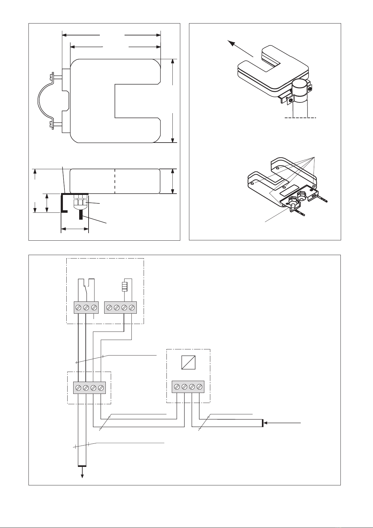
Installation
The device holder is designed to be mounted on a pole.
Alternatively, it can also be mounted on a beam or wall
surface (Fig. 7). When mounting, ensure that the sensor
window is facing northward as much as possible (Fig. 7).
Electrical connection
The device is electrically connected as shown in Fig. 6.
After removing the five enclosure screws (Fig. 7), the
cover of the sensor can be removed.
OTICEN Due to the use of PTCs as heating elements,
power consumption reaches a high peak
value during the switch-on phase. It must be
limited to max. 50 W by suitable measures
(e.g. power supply unit art. no.629054).
The device can be supplied with DC or AC
voltage.
After completing the connection work, firmly tighten the nut
of the cable gland to ensure that the inside seal encloses
the connecting lines in a watertight manner. If you are
working with a combined connecting line for heating and
power supply, leave the blind plug in the vacant gland.
Close the enclosure cover and retighten the five screws
uniformly with a torque of 1Nm to 2Nm to prevent water
from entering into the device. A JY(St)Y 2 x 2 x 0.8 mm
ø line can be used for the connection, although 4 x AWG
24CUL (UV-resistant) is recommended.
816872_j•en•2016-10-01We reserve the right to carry out improvements
2
OTICEN Sensor lines are not permitted to be routed
alongside 230 V lines to avoid the coupling of
interference.
Commissioning
After the device is fully mounted and the power supply is
connected, the device is ready for operation.
Setting the switch-off delay
The switch-off delay is the time from the last measured
precipitation event until the relay drops out. This time can
be set on the installed encoding switch S1 (Fig. 2). The
following table shows the switch settings and the associ-
ated delay time:
DIP 1: De-activation delay
S1 S2 S3 S4
Time (Seconds)
0000 0
1000 52
0100 05
1100 57
0010 001
1010 521
0110 051
1110 571
0001 002
1001 522
01 01 052
1101 572
0011 003
1011 523
0111 053
1111 573
DIP1
1234
ON DIP
Factory-
setting
Fig. 2 Setting the switch-off delay
DIP 1DIP 2
Fig. 3 Position of encoding switch
Setting the event filter
The number of drop events that must fall through the
sensor window within 50seconds for precipitation to be
registered can be set on the encoding switch S2 (Fig. 3).
The following table shows the switch settings and the as-
sociated number of drop events:
DIP 2: Event filter
S1
0000 0
1000 1
0100 2
1100 3
0010 4
1010 5
0110 6
1110 7
0001 8
1001 9
01 01 01
1101 11
0011 21
1011 31
0111 41
1111 51
S2 S3 S4 Number of
Drop events
DIP2
1234
ON DIP
Factory-
setting
This setting does
not make sense
and should be
avoided!
Fig. 4 Setting the event filter
Maintenance
There are no parts within the device that require mainte-
nance. The sensor should occasionally be checked for dirt
(e.g. bird droppings) and cleaned carefully. Commercially
available household cleaners may be used. Solvents may
not be used.
3
816872_j•en•2016-10-01 We reserve the right to carry out improvements
Liability
Failure to comply with the product information in these
instructions and use of the unit in a manner that contra-
venes its intended use and purpose may result in the
manufacture refusing to honour warranty claims for prod-
uct damage. In this case, liability for consequential harm
to persons or damage to property will also be excluded.
Follow the instructions in the operating manual of your sun
shading system. The automatic or manual operation of
the sun shading system when iced over as well as using
the sun shading system during severe weather may cause
damage and must be prevented by the user by taking suit-
able precautions.
Disposal
After its use, the device must be disposed of according to
legal regulations or returned to your local recycling centre!
Technical data
Sensor
Precipitation
(infrared)
Min. Typ. Max. Unit
Supply
Operating voltage 20.4 24 27.6 V AC
V DC
Current consumption
at 24V
30 1000 mA
Output
1 x relay contact,
unipolar switch
230 V AC
Current capacity
(cos ϕ = 1)
4A AC
Switch-off delay 25 200 375 s
Enclosure
Dimensions See Fig. 5
Degree of protection/safety class
Degree of protection IP65
Safety class III
Connection
All connections Screwed terminals
Miscellaneous
Conformity Viewable at www.warema.de
The device meets the EMC guidelines for use in residen-
tial and commercial areas.
Ambient conditions
Operating temperature -35 60 °C
Article numbers
Sensor 623 045
Universal
power supply unit,
24 V DC,
distributor installation
629 041
Universal
power supply unit,
24 V DC,
surface-mounted
629 054
Universal
power supply unit,
24 V AC,
surface-mounted
629 065
WAREMA Renkhoff SE
Hans-Wilhelm-Renkhoff-Strasse 2
97828 Marktheidenfeld
Germany
816872_j•en•2016-10-01We reserve the right to carry out improvements
4
Skintop
PG 9
Aluminium,
4 mm
Blanking plug
40
30
39 125 mm
148 mm
135 mm
69 mm
Fig. 5 Dimensions
Junction box
on site
Sensor Precipitation
(infrared)
WA
Power supply unit
for Sensor Precipitation
24 V DC or 24 V AC
NL1
Supply line
230 V AC
L
N
NYM-J 3×1.5 mm²
H05RR-F 4 G 0.75 BK
4 x AWG 24 C UL BK*
JY (St) Y 2×2×0.8 mm ∅
max. line length 200 m**
* Recommended line type when routing outdoors
** for twisted pair line
Attention!
Contacts R and W are closed when de-energised,
which means that precipitation will be indicated.
to the sun shading
control systemA
R+‒
+
‒
Fig. 6 Wiring diagram
Enclosure-
screws
Wall-mounting
Standpipe mounting
Face the sensor
window northwards!
Blanking plug
Fig. 7 Installation instructions

This manual suits for next models

1

Other WAREMA Accessories manuals

WAREMA 310 Specification sheet

WAREMA

WAREMA 310 Specification sheet

WAREMA 310 Manual

WAREMA

WAREMA 310 Manual

WAREMA Perea P70 User manual

WAREMA

WAREMA Perea P70 User manual

WAREMA WMS User manual

WAREMA

WAREMA WMS User manual

WAREMA Perea P70 User manual

WAREMA

WAREMA Perea P70 User manual

WAREMA WMS Socket User manual

WAREMA

WAREMA WMS Socket User manual

WAREMA Photo 623 067 User manual

WAREMA

WAREMA Photo 623 067 User manual

Popular Accessories manuals by other brands

LEI Extras TS-1BL Analog Temp Sensor installation instructions

LEI Extras

LEI Extras TS-1BL Analog Temp Sensor installation instructions

Alula RE206M manual

Alula

Alula RE206M manual

Mecon mag-flux F5 quick start guide

Mecon

Mecon mag-flux F5 quick start guide

Apogee ensemble user guide

Apogee

Apogee ensemble user guide

IMI SENSORS 640B02 Installation and operating manual

IMI SENSORS

IMI SENSORS 640B02 Installation and operating manual

OPTEX FA V2 Series instruction manual

OPTEX FA

OPTEX FA V2 Series instruction manual

Emos P0069 quick start guide

Emos

Emos P0069 quick start guide

Airvana IP-RN 80000 Installation and commissioning guide

Airvana

Airvana IP-RN 80000 Installation and commissioning guide

kobi LX06 manual

kobi

kobi LX06 manual

Hytronik HC407VDS instruction manual

Hytronik

Hytronik HC407VDS instruction manual

Enerlites MPC-50H Installation instructions and owner's manual

Enerlites

Enerlites MPC-50H Installation instructions and owner's manual

Goldair GEK200 operating instructions

Goldair

Goldair GEK200 operating instructions

DÖRR KOMPAKT X42 instruction manual

DÖRR

DÖRR KOMPAKT X42 instruction manual

AGI WESTFIELD 1500 Series Operator's manual

AGI

AGI WESTFIELD 1500 Series Operator's manual

RCA PS73102C2 user guide

RCA

RCA PS73102C2 user guide

Ravpower Prime RP-PB183 user guide

Ravpower

Ravpower Prime RP-PB183 user guide

Knick MemoView ZU1059 installation guide

Knick

Knick MemoView ZU1059 installation guide

Playmate Remote Pad quick start guide

Playmate

Playmate Remote Pad quick start guide

manuals.online logo
manuals.online logoBrands
  • About & Mission
  • Contact us
  • Privacy Policy
  • Terms and Conditions

Copyright 2025 Manuals.Online. All Rights Reserved.