Warmco HR10 User manual

INSTRUCTION MANUAL
PREMIX UNIT AIR HEATER
TYPE HR
Production from 2019
THIS DOCUMENT MUST ABSOLUTELY BE READ BEFORE STARTING THE
INSTALLATION.
INSTRUCT USER AND LEAVE THIS DOCUMENT WITH HEATER FOR
REFERENCE.
Date: 01-02-2019
Instruction manual version HR-GB-4001-a
Heaters for GB
heaters for natural gas G20 and Propane

Instructions condensing Air heaters type HR version HR-GB-4001-a
Page
Introduction
This installation and user manual is produced specifically for the gas, electrical and mechanical
installer , it also gives instructions how to use and maintain the heater.
It is most important to follow the directions in this booklet for safe operation of this product.
1Content:
Page
CONTENT: 2
1
GENERAL 3
1.1
S
AFETY WARNINGS
3
1.2
I
MPORTANT CHECKS BEFORE INSTALLATION
3
1.3
G
UARANTEE
4
2
TECHNICAL DETAILS: 5
3
INSTALLATION 8
3.1
P
OSITIONING
8
3.2
G
AS CONNECTION
10
3.3
E
LECTRICAL CONNECTION
10
3.4
A
IR INTAKE
/
COMBUSTION PRODUCTS DISCHARGE
12
3.5
C
ONDENSATE DISCHARGE
14
3.6
I
NSTALLATION
R
OOF OR
W
ALL TERMINAL
14
7
FUNCTIONING OF THE UNIT 17
7.1
G
ENERAL
17
7.2
B
URNER CYCLE
17
7.3
D
ELTA
-T-
REGULATION
(
TEMPERATURE CONTROLLED DE
-
STRATIFICATION FAN
) 17
7.4
S
UMMER VENTILATION
18
7.5
H
IGH LIMIT PROTECTION
18
7.6
F
LUE
T
RANSPORT
S
UPERVISION
18
8
PUTTING INTO OPERATION AND ADJUSTMENT 18
8.1
G
ENERAL
18
8.2
S
TART BY USING THE THERMOSTAT
18
8.3
S
TART THROUGH THE DISPLAY IN THE HEATER
19
9
ADJUSTING THE GAS-CONTROL 19
10
PROBLEM SOLVING 20
10.1
G
ENERAL
20
11
MAINTENANCE / SPARE PARTS 22
11.1
G
ENERAL INSPECTION
22
11.2
I
NSPECTION OF THE HEATER
23
11.3
I
GNITION ELECTRODE
23
11.4
T
HERMOSTAT CABLE
23
11.5
I
NSTALLATION WITH MODULATING ROOM THERMOSTAT
23
11.6
I
NSTALLATION OF MORE HEATERS ON ONE THERMOSTAT
24
12
ELECTRICAL DIAGRAM 26
13
EXPLODED VIEWS AND SPARE PARTS 27
13.1
S
PARE PARTS
27
13.2
E
XPLODED VIEW
HR10-60 27
13.3
E
XPLODED VIEW
HR80-120 27
13.4
E
XPLODED VIEW
HR80-120 28

Instructions condensing Air heaters type HR version HR-GB-4001-a
Page
2Genera
2.1 Safety warnings
The installation and maintenance of this air heater should be performed by an authorized
qualified competent installer in accordance with this manual, using calibrated equipment.
This heater must be installed in accordance with the manufacturer's instruction and local codes.
The qualified installer needs to follow the local health and safety codes.
This appliance may only be operated and serviced by sufficient instructed people. Failing to
follow the instructions can lead to damage to the appliance or the installation.
This appliance can be used by children aged from 8 years and above and persons with reduced
physical, sensory or mental capabilities or lack of experience and knowledge if they have been
given supervision or instruction concerning use of the appliance in a safe way and understand
the hazards involved. Children shall not play with the appliance. Cleaning and user
maintenance shall not be made by children without supervision.
Always follow these safety instructions:
•Make sure that the area around the appliance is dry when working on the appliance.
•Always close the doors and inspection hatches unless adjusting and checking the heater.
Before working on an already installed heater:
- Set the thermostat to lowest setting.
- Close the main gas switch. The main gas switch should be situated upstream in the gas
line near the heater.
- Turn off all electric power to the appliance
After working on the heater always check for gas leaks.
Close the doors and hatches of the appliance.
2.2 Important checks before installation
2.2.1 Pre-check instructions
Before unpacking and installation, please check (i.e. on the data badge) if the heater is in
accordance with the order and if it is suitable for the local present provisions (gas type, gas
pressure, electrical supply etc.)
The heater has been tested in detail on safety and correct operating settings before leaving the
factory. It has been adjusted for the type of gas that is stated on the data badge. Should there
be any doubt, please contact your supplier.
2.2.2 Gas type
The unit is suited for OR Natural gas OR Propane gas. On the labels on the packaging and the
heater can the gas type that the heaters is set up for can be found. In case the heater needs to
be converted to another gas type contact your supplier. It can only be converted by the
manufacturer or its representative.
2.2.3 Standards
The Installation must comply with all applicable local and national standards.
The installation of the air heater must be in accordance with the relevant requirements of the
Gas Safety regulations (for example in GB; The Institute of Gas Engineers IGE UP-1 and 2),
building regulations and the IIE regulations also incorporating the gas safety (installation and
use) regulations. Other national and/or local regulations may apply (the Local Authority ,Fire
Officer and Insurers)

Instructions condensing Air heaters type HR version HR-GB-4001-a
Page
2.2.4 Protection from water and dust
The heater is not waterproof. This means that it may not be exposed to rain, spry or dripping
water. The IP classification is IP00B
The appliance is not designed for use in a very dusty environment. Dust may accumulate in the
heater and may cause a defect of the heater. This is also the case for the room-thermostat.
2.2.5 Protection against dust
The appliance is not designed for use in a very dusty environment. Dust may accumulate in the
heater and may cause a defect of the heater. This is also the case for the room-thermostat
2.2.6 Temperature
Do not install the heater in places where the temperature can rise above 35°C. At higher
temperatures the internal components will degrade much faster. This is not covered by the
guaranty.
2.2.7 Corrosive environment
The heater should not be installed in areas containing any corrosive or explosive vapours. It
should be prevented that chlorine or other corrosive containing vapours are sucked into the air
intake. These vapours will result in corrosion of the heat exchanger and a leakage of
condensate and flue gas. Defects caused by this are not covered by guaranty. Please consult
your supplier. This is also the case for the room-thermostat
2.2.8 Installation distances
Keep sufficient distance between the heater and any obstruction , in connection with safety and
access for service and maintenance. Pay particular attention to any flammable materials.
Please take into account the possibility to open the door of the heater for the necessary service
and maintenance work . Make sure the air flow to and from the heater is unhindered. Any
obstacles should be a minimum of 5 metres away from the front of the heater. Read the
chapter “Installation” carefully.
2.2.9 Condensate discharge
This is a condensing heater. This means a condensate water discharge system should be
installed according to local regulations. Never block this discharge.
2.2.10 Maintenance
For the safe and proper operation of the heater periodical maintenance is necessary. When the
heater is not serviced and cleaned in time, it could lead to damage of the heater or its
surroundings.
2.3 Guarantee
The guarantee becomes void when the air heaters are not installed and serviced in accordance
with this manual.

Instructions condensing Air heaters type HR version HR-GB-4001-a
Page
3Technica detai s:
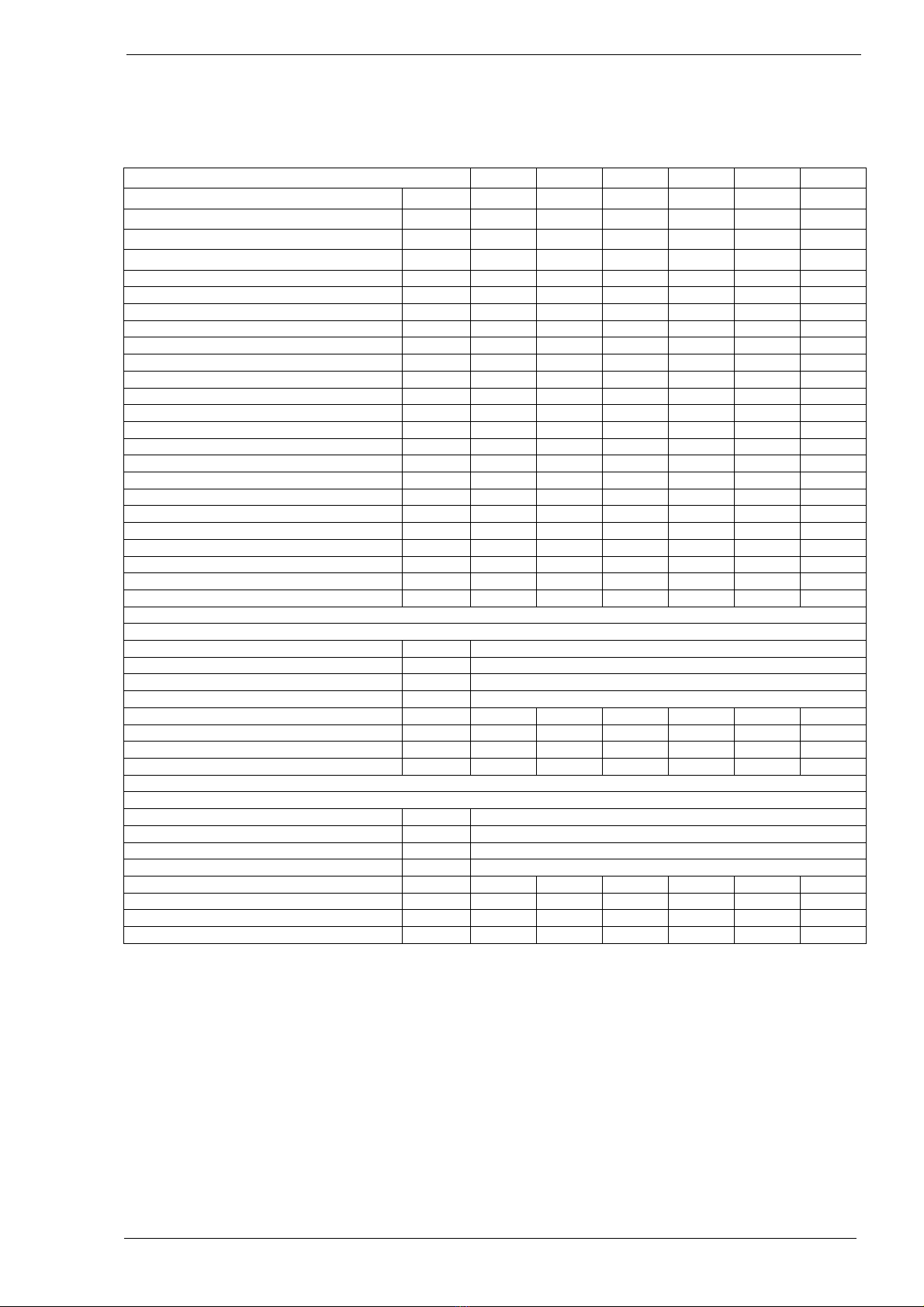
Type HR 10 20 30 40 50 60
Maximum nominal heat input (H.I.) kW 12,5 20,0 30,0 40,0 50,0 60,0
Minimum nominal heat input (H.I.) kW 4,0 6,0 9,0 12,0 15,0 18,0
Efficiency max. power % 96,0 96,0 96,5 97,0 96,5 96,6
Efficiency 30% power % 106,0 106,0 106,0 106,5 106,0 106,0
Maximum heat output kW 12,0 19,2 29,0 38,8 48,3 58,0
Minimum heat output kW 4,2 6,4 9,5 12,8 15,9 19,1
Max air output (warm) m3/hr 2.000 2.600 3.000 4.500 5.000 6.000
Throw horizontal (max) m 15 20 23 26 28 30
Gas connection G” ½” bin ½” bin ¾” bui ¾” bui ¾” bui ¾” bui
Electrical Voltage [50 Hz] V 230 230 230 230 230 230
Electrical power max. kW 0,250 0,250 0,250 0,450 0,450 0,600
Electrical power min.
kW 0,250 0,250 0,250 0,450 0,450 0,600
Electrical power standby
kW 0,004 0,004 0,004 0,004 0,004 0,004
Electrical current A 1,1 1,1 1,2 2,0 2,6 2,6
Emission efficiency, (ηs,flow) % 97,6 96,4 94,6 95,0 94,8 94,6
Seas. space heating efficiency % 90,4 90,1 88,7 89,9 89,2 89,4
NOx emission (GCV) mg/kWh 30 21 33 40 31 44
NOX class 5 5 5 5 5 5
Flue amount max. kg/hr 19,4 31,1 48,3 64,2 80,2 96,2
Thermostat bus system (low voltage) Yes Yes Yes Yes Yes Yes
Sound level (average @ 4 meter) dBA 45 45 45 47 48 49
Suspension height horizontal throw min. m 1,7 1,7 1,7 1,7 1,7 1,7
Flue length max. m 9 9 9 9 9 9
Weight m 45 50 75 85 105 110
Natural gas
G20, heater version 3.3
Nominal supply pressure G20 mbar. 20
Supply pressure (min-max) G20 mbar. 17-25
Gas category Cat. I2H
Class Class. B23, C13, C33
Max gas consumption G20 m3/hr 1,3 2,1 3,2 4,2 5,3 6,3
CO2 High G20 % 9,5 9,5 9,2 9,2 9,2 9,2
CO2 Low G20 % 9,0 9,0 8,8 8,8 8,8 8,8
CO (@ 0%O2) mg/kWh 4 5 1 1 3 3
Propane, G31, heater version 3.4
Nominal supply pressure G31 mbar. 30-50
Supply pressure (min-max) G31 mbar. 25-50
Gas category Cat. I3P
Class Class. B23, C13, C33
Max gas consumption G31 kg/hr 1,0 1,6 2,4 3,2 4,0 4,8
CO2 High G31 % 10,7 10,7 11,0 11,0 11,0 11,0
CO2 Low G31 % 10,3 10,3 10,5 10,5 10,5 10,5
CO (@ 0%O2) mg/kWh 13 8 3 1 1 1

Instructions condensing Air heaters type HR version HR-GB-4001-a
Page
HR80, 100, 120
The HR80 & 100 & 120 have double heat exchangers placed on top of each other with
combined connections.
Type HR 80 100 120
Maximum nominal heat input (H.I.) kW 80,0 100,0 120,0
Minimum nominal heat input (H.I.) kW 24,0 30,0 36,0
Efficiency max. power % 97,0 96,8 96,5
Efficiency 30% power % 105,0 105,0 105,0
Maximum heat output kW 77,6 96,8 115,8
Minimum heat output kW 25,2 31,5 37,8
Max air output (warm) m3/hr 8.500 10.000 12.000
Throw horizontal (max) m 30 30 33
Gas connection G” 1” int. 1” int. 1” int.
Electrical Voltage [50 Hz] V 230 230 230
Electrical power max. kW 0,900 1,000 1,050
Electrical power min.
kW 0,900 1,000 1,050
Electrical power standby
kW 0,010 0,010
0,010
Electrical current A 3,9 4,4 4,7
Emission efficiency, (ηs,flow) % 95,5 95,6 95,5
Seas. space heating efficiency % 88,8 89,0 89,1
NOx emission (GCV) mg/kWh 38 33 36
NOX class 5 5 5
Flue amount max. kg/hr 128,4 160,4 192,4
Thermostat bus system (low voltage) Yes Yes Yes
Sound level (average @ 4 meter) dBA 50 51 52
Suspension height horizontal throw min. m 1,7 1,7 1,7
Flue length max. m 9 9 9
Weight m 180 195 205
Natural gas G20, heater version 3.3
Nominal supply pressure G20 mbar. 20
Supply pressure (min-max) G20 mbar. 17-25
Gas category Cat. I2H
Class Class. B23, C13, C33
Max gas consumption G20 m3/hr 8,4 10,6 12,6
CO2 High G20 % 9,2 9,2 9,2
CO2 Low G20 % 8,8 8,8 8,8
CO (@ 0%O2) mg/kWh 1 3 3
Propane, G31, heater version 3.4
Nominal supply pressure G31 mbar. 30-50
Supply pressure (min-max) G31 mbar. 25-50
Gas category Cat. I3P
Class Class. B23, C13, C33
Max gas consumption G31 kg/hr 6,4 8,0 9,6
CO2 High G31 % 11,0 11,0 11,0
CO2 Low G31 % 10,5 10,5 10,5
CO (@ 0%O2) mg/kWh 1 1 1

Instructions condensing Air heaters type HR version HR-GB-4001-a
Page
490 125
285
245
M10
420
495
420
680
M10
M10
100 110 85
65
65
85
35
O
40
IN
O
80
OUT
O
80
Gas 1/2"
Type 10 & 20 575
795
670
565
575
650 125
470
545
M10
4x M10
M10
115140 110
100
105
Gas 3/4" ext.
IN
O
80
OUT
O
80
325
400
180
=
=
35
85
180 815
470
650 125
4X M10
565
670
1065
Gas 3/4" ext.
100
115
105
11014035
85
IN
O
80
OUT
O
80
O
40
O
40
Type 30 & 40
Type 50 & 60
280
280
280
840
815227
600
812 75
280
1115
1090
1195
840
87
462
11045
158
158
Gas 1" int.
Ø40
Type 80, 100 & 120
225
IN Ø130
OUT Ø130

Instructions condensing Air heaters type HR version HR-GB-4001-a
Page
4Insta ation
4.1 Positioning
•Check that the support is solid enough.
•The heater is designed as free hanging. The heater
should be able to blow the warm air free from any ducting
or obstacles. Also the air intake should be free.
•Keep sufficient distance between the heater and any
obstruction , in connection with safety and access for
service and maintenance. See the drawings in this
chapter. Pay particular attention to any flammable
materials. Please take into account the possibility to
open the door of the heater for the necessary service
and maintenance work . Make sure the air flow to and
from the heater is unhindered. Any obstacles should be
a minimum of 5 metres away from the front of the
heater.
•The heater can be installed horizontally or on an angle
of maximum 45 degrees downwards.
•When the heater is installed other than horizontal,
Always re-adjust the CO2 setting from the gas valve.
•The heaters type 10 and 20 are provided with 2 off
M10 threaded sockets as fixing points (see the
dimension diagram).
•The types 30 and 40 have in the middle a M10 socket and also 4 sockets on the top corners
of the heater
•The types 50 and 60 have on the top and bottom 4 M10 sockets. (see drawings)
•Use preferably the Winterwarm suspension kits.
•Make sure that after fitting, there is no mechanical tension on any connecting gas or electric
supplies.
•If the heater is installed with the air stream vertical downwards the maximum suspension
height is 8 meters. Otherwise the warm air will not reach the floor.
Attention:
See the application-restrictions in this manual (Chapter 2) for further installation restrictions.
min 250
10 t/m 30 min. 500 mm
40 t/m 60 min 660 mm

Instructions condensing Air heaters type HR version HR-GB-4001-a
Page
B
150
390
A
C
XR10-30 XR40-60
HR10-20 HR30-40
A 550 665
B 640 815
C 800 990
Available suspensions:
Standard bracket for type HR10 to 40 Design bracket type HR10 and 20
Horizontal horizontal
Suspension adapter for type HR10 and 20
M10 threaded bar

Instructions condensing Air heaters type HR version HR-GB-4001-a
Page
Wall console set HR30 up to 120
Art. Nr. : GA8580
1200
1200
Seeinstallationmanual
45°
15° & 30°
Horizontal
15° 30° 45°
Horizontal
4.2 Gas connection
The gas supply line has to meet the national valid requirements and possibly the local
requirements of the building inspector, police or fire brigade. (In GB it must comply with Gas
Engineers publication UP-1 and UP-2 together with BS 6891.
A manual isolation valve in the supply line must be placed within reach of the heater, and all gas
lines must be mounted without any mechanical tension.
When testing the supply lines with pressures above 60 mbar, this manual valve at the heater
must be closed.
The working and standing supply pressure must be a minimum of 17 mbar, and a maximum of
30 mbar ,measured at the inlet pressure nipple of the gas control in the heater
In case the heater needs to be converted to another gas type contact your supplier. It can only
be converted by the manufacturer or its representative.
4.3 Electrical connection
4.3.1 230Vac supply
The installation must comply with local and
national requirements, ( as well as IEE
regulations)
Never use a room thermostat to interrupt the
electrical supply to the heater!
Make provisions to completely isolate the heater for maintenance purposes. This can be an
isolation switch (min.3mm contact opening gap) , a power plug or a non-switched fuse spur.
The wiring diagram for the heater can be found towards the end this manual.
The supply is 230Vac. with earth. The control circuit is a two wire low voltage bus
communication.
HR30 - 60
HR30 - 60
HR30 - 120HR30 - 120

Instructions condensing Air heaters type HR version HR-GB-4001-a
Page
4.3.2 Room thermostat
The heater can only be controlled by special modulating Winterwarm room thermostats:
The Multi Therm Comfort; modulating digital clock thermostat with optimiser. It can control 1 to
8 air heaters HR10 up to HR60 or 1 to 4 air heaters HR80 up to 120.
The Multi Therm Standard; modulating digital thermostat. It can control 1 to 8 air heaters
HR10 up to HR60 or 1 to 4 air heaters HR80 up to 120.
The Interface printboard; special designed interface module for connecting the air heaters with
Building Mangagement Systems. (0-10V (modulating input) signal, high/low signal,
external reset and other different in and outputs.
ON/OFF thermostat
The heater cannot be controlled with a simple on/off thermostat.
In all cases the communication between heater and thermostat is based on a two wire, low-
voltage connection. In the appliance the wire for the thermostat has to be connected to
connection 4 and 5 (see also electrical wiring diagram) Attention: This also needs a change in
the settings on the print board.
4.3.3 Thermostat installation
When mounting the thermostat, take attention to the following items:
•Mount the thermostat in a place where the air can circulate free pass the thermostat. Take
notice that the sun does not shine directly upon the thermostat (in the winter). Do not
place the thermostat on a cold wall. Place the thermostat on an inner wall free from
draught.
•Never place the thermostat within the throw of the heater.
•Never mount the thermostat near aerials of internal communication networks. These emit
radiation that could lead to disturbance of the thermostat. Always keep some meters
distance.
•In all cases the communication between the heater and the thermostat is based on a two
wire, low-voltage connection. In the appliance the wire for the thermostat has to be
connected to connection 4 and 5 (see also electrical wiring diagram).
Cable specification: signal cable, 1x2x0,8 (shielded and twisted)
Maximum length 250m.
If the cable is chosen too thin, the signal will become too poor. If the cable is not shielded and
twisted the signal might become disturbed in an EMC unfriendly environment.
Keep the thermostat cable separated from mains cables. Connect the earth shield of the cable
only to the earth terminal in the heater.
If these guidelines are not followed it may result in malfunction of the installation or worse, it
could damage the thermostat or the electronics in the heater.
4.3.4 Fuse
On the heater control board there is 1 fuse. See electrical wiring diagram.
F1 and in the power supply of the heater. Replace the fuse only by a fuse of the same type, 5AT

Instructions condensing Air heaters type HR version HR-GB-4001-a
Page
4.4 Air intake / combustion products discharge
Check for compliance with local / national regulations.
Only the described flue material may be used. This goes for the roof or wall terminal and also
for the piping between the heater and the terminal. Only so the installation is approved.
Always connect a roof or wall terminal for condensing appliances, otherwise condensate can
form ice in the winter on the terminal.
In some cases the roof terminal has to be at least 0,5m above roof level (depending on local
regulations).
Pay attention on fresh air ventilation openings on the building. There are local distance
restrictions on placing a flue terminal near the ventilation openings.
4.4.1 Flue material
It is only allowed to use CE marked flue material from the manufacturer Muelink &
Grol (M&G) and Burgerhout, type Alu-fix temperature class minimum T120.. These
Flue systems can be bought at your supplier.
Only use one flue pipes from the same diameter as the flue spigots on the heater.
Different manufacturers have different connections systems from the flue pipes. It
is not allowed to combine systems from different manufacturers.
4.4.2 Maximum flue length
The maximum pressure drop in either the air supply pipe, or the flue pipe ,must
not exceed 9 metres straight pipe , excluding the terminal. Whenever bends are
used the pressure drop is greater and therefore a 90°bend will count as 2 metres and a 45°
bend as 1 metre. All flue pipes must be of the same diameter as the flue spigots on the heater,
and all flue joints must be sealed. For further information regarding the flue system please
contact your reseller.
4.4.3 Flue terminals
Only the flue terminals that are provided with the heater may be used.
These terminals are certified together with the heater.
The following terminals are allowed:
HR10-60
- Concentric roof terminal type M&G Skyline 80-80 article: IA8214
•for h>0,5m above roof IA8217
- Concentric wall terminal type M&G HR80-80 article: IA8216
HR80-120
- Concentric roof terminal type M&G 130-130 HR article: IA8307
- Concentric wall terminal type M&G 130-130 HR article: IA8314

Instructions condensing Air heaters type HR version HR-GB-4001-a
Page
575
1370
O
125
80
O
HOH 110
max 300
135 610
O
125
80
HOH 110
HR10 up to 60
horizontal discharge art.: IA8216
HR10 up to 60
vertical discharge: art.: IA8214
roof distance >0,5m: IA8217
The following flue terminals are allowed:
1775
O
200
990
O
130
HOH 225
max.300
300 690
HOH 225
O
130
O
200
HR80 up to 120
horizontal discharge
art.: IA8314
HR80 up to 120
vertical discharge
art.: IA8307

Instructions condensing Air heaters type HR version HR-GB-4001-a
Page
4.5 Condensate discharge
The condensate discharge pipe is on the bottom of the heater. The separate delivered siphon
has to be connected to the condensate Ø40mm PVC pipe. On the siphon a pipe Ø 40mm can
be mounted. The discharge system after the sifon has to be minimum Ø25mm and mounted
with an inclination to the sewer. The advised inclination should be minimum 50mm per meter.
The horizontal length should not exceed 5 meter.
The condensate should connected according to local and national regulations. Do not let the
condensate drip on the roof or roof edge outside the building, dangerous ice can be formed in
the winter. Condensate should be drained away to the sewer.
The condensate outlet from the heater should never be closed.
Protect the condensate drain from freezing. Ice can also close the condensate drain.
To be sure that the condensate can always flow out of the heater, an extra siphon should be
mounted before connecting to the sewer.
When the condensate discharge system is placed the siphon has to be filled with water. This is
important because otherwise the flue gases can flow into the room where the heater is placed.
HR10 up to 120
Horizontal
!
Max. amount condensate rate:
HR10
HR20
HR30/35
HR40
HR50
HR60
HR80 HR100
HR120
Max. Condensate l/h 2 3 4 6 8
4.6 Installation Roof or Wall terminal
Algemeen
•Check the components on possible damages.
•Combine only with components from same materials and manufacturer.
•Install after national regulation.
•Outside can be cleaned with a wet towel or with some detergent.

Instructions condensing Air heaters type HR version HR-GB-4001-a
Page
Installation Roof terminal
1. Check the components on possible damages.
2. Taking the roofing into account, determine the type of weather collar synthetic file or universal
pitched roof flashing; for a flat roof an aluminium flat roof flashing.
3. Determine where the flue terminal will be positioned.
4. Make a hole for the flue terminal from the outside. Ensure that no saw dust or dust gets into the
appliance.
5. Fit the weather collar..
6. Carefully insert the flue terminal through from the outside. Attention: do not tum the cap.
7.
Put the flue terminal into a vertical position using an air level. (If desired, cover plates, to be
supplied separately,can be fitted)
8. Fix the supplied wall clamp round the flue terminal and fit
it to the roof construction. Do not tighten the clamp yet.
9. Fit the gasket and the twin-tube connection. Make sure
that the gasket is not damaged. Ensure that the flue tube
and the air inlet tube are not exchanged; the flue tube is
the pipe in the centre of the flue terminal.
10.
Finally, secure the roof wall clamp and check that all
steps have been carried out correctly.
Installing Wall terminal
1. Check the components on possible damages.
2. Determine where the flue terminal will be positioned.
3. Make a hole for the flue terminal. Ensure that no saw dust or dust gets into the appliance.
4. Carefully insert the flue terminal the outside. Attention: do not tum the cap.
5. Fix the terminal horizontally using an air level
6. Mark the holes and drill the holes in the outside wall for the fixation of the terminal.
7. Fix the terminal with screws. Eventually seal the fixation with kit.
8. Fix the shield on inner wall.
9. Fit the gasket and the twin-tube connection. Make sure that the gasket is not damaged. Ensure
that the flue tube and the air inlet tube are not exchanged; the flue tube is the pipe in the centre of
the flue terminal.
10. .Check that all steps have been carried out correctly.

Instructions condensing Air heaters type HR version HR-GB-4001-a
Page
4.6.1 Installation from the flue system parts
These basic instructions are for the flue material that go with this heater.
Elements system ALU FIX thick wall
General
•Distance to conbustionable materials around the flue parts minimal 40mm.
•Use the brackets that go with the flue system.
•
Different manufacturers have different connections systems from the flue pipes. It is not
allowed to combine systems from different manufacturers
•The female sockets should have an depth of minimal 40 mm.
•Install without mechanical force on the parts.
•Inclination towards the appliance of 3 degrees (50 mm per meter) to allow the condensate to flow
to the heater.
Sealings
•If the flue parts need to be cut, Clean and round the edges. Sharp edges will damage the seal.
•Follow the instructions from the manufacturer when the connections need to be fixed.
•Do not drill or screw in the parts.!
•Do not try to seal with kit, foam or tape.
•Lubricate the connections only with allowed lubricant from the manufacturer. Maximum 1% of
soap or water is allowed.
•ATENTION! Do not use grease, Vaseline or oil
Fixation
•Fix every elbow on or near the socket.
Exception when connecting the appliance: when the flue pipes before and after the elbow
are shorter than 0.25m, then the 2nd element after the elbow needs to be fixed with a
bracket.
•Horizontal and non-vertical flue pipes:
Maximum distance between brackets 1 m.
On tensile joints, (following the manufacturer’s instructions) Maximum distance between
brackets 2 m.
The distance between the brackets should be spread out equally.
•Vertical piping:
Maximum distance between brackets 2 m.
The distance between the brackets should be spread out equally.
•Inside a shaft:
Check the components on possible damages or blockage..
Check that the pipe is under the right inclination.
Mark the flue pipes and fresh air pipes to avoid a mistake.
Check that the pipes extend minimum 50mm when going through a wall or other obstacle.
Fix the last element before entering the shaft. If this is an elbow, also the 2nd element
may be fixed.
•ATENTION, every system needs to have at least 1 bracket. The first bracket needs to be within
the first 0,5m from the appliance..

Instructions condensing Air heaters type HR version HR-GB-4001-a
Page
5Functioning of the unit
5.1 General
The unit can heat as well as ventilate. By using the temperature-sensor on the unit and the one
in the room-thermostat, the temperature-difference between the two in the room is monitored.
Should the difference become higher than a set value, due to the fact that warm air has
accumulated underneath the roof, the system-fan will start and push the warm air down, acting
as a de-stratification fan.
5.2 Burner cycle
The status and burner cycle is showed on the display in the heater
Display
S
t
atus
D
escription
0
Init
Initi
alisatio
n
of
the control b
oard
1
Reset
So
ftware reset
2 Stand-by Standby, waiting for heat demand
3
P
re
-
check
Zero
position check
pressure switch
4 Pre-purge 30 seconds of pre ventilation from the combustion fan. The
press
ure swit
ch is checked
.
5 Pre-ignition Ignition without opening the gas valve
6
Igniting
Igniti
on
(5
sec)
,
g
as
valve opens
7 Flame check Check if the flame is present
8
B
urn
The heater b
urns and s
tarts to modula
te.
9 Minimum Before the flame stops, the burner will modulate to minimum
pow
e
r
10
B
urner off
G
as
valve closes,
t
he flame stops
11 Post Purge Burner fan purges with fresh air
Syst
em
fan
c
ools t
he heat exchanger
Minimum burn time 4 minutes!
The heater will always burn minimum 4 minutes, even if the heat demand stops. This to avoid
an unnecessary large amount of start and stops.
The heater will try 2 times to ignite before it stops and gives an error.
5.3 Delta-T-regulation (temperature controlled de-stratification fan)
In case there is no heat demand, the delta-T-regulation will be active.
When the temperature-difference between the sensor on the unit (the NTC) and the sensor in
the thermostat is bigger than the set value (factory setting standard 8°C), the system fan will
start, at a regulated speed, depending on the differential temperature difference. This operation
ensures an even temperature distribution throughout the building, thus acting as a fully
automatic variable de-stratification fan.
Switch of delta-T-regulation
Should this delta-T-regulation not be required, in the Menu Program Settings on the room
thermostat this regulation can be switched off. See user manual of the special Winterwarm
Room thermostat.

Instructions condensing Air heaters type HR version HR-GB-4001-a
Page
5.4 Summer ventilation
It is possible to let the ventilator run on a certain speed in the summer. Please follow the
instructions in the manual from the thermostat.
5.5 High limit protection
5.5.1 T max. Heat exchanger
The unit contains 2 temperature protections. The NTC thermostat monitors the air temperature
electronically. Should the temperature, as a first step, become too high, the burner will modulate
to the minimum input and the system fan will modulate to the maximum speed.
When the temperature still increases, the burner will switch off. The display will show E05 / E36.
When the heat exchanger has been cooled to normal levels the burner will start automatically.
Should the temperature increase to an unacceptable level, the heater stops. The display will
show L31. Only after a manual reset the heater can start again. Manual reset can be done on
the electronic circuit board or with the special Winterwarm Room thermostat
5.5.2 T max. Flue gas
For the application of plastic flue material on the HR heaters the maximum flue gas temperature
is monitored (Tflue < 120 °C). A temperature sensor in the flue outlet the heater monitors the
temperature of the flue. When the flue temperature is too high (Tflue > 110 °C), the burner
modulates its capacity to the minimum. When the temperature keeps rising, and reaches
115°C, the burner stops. When after an automatic restart the situation repeats itself the heater
will lock out. The error L-16 will be show in the display.
5.6 Flue Transport Supervision
The unit is provided with a pressure switch to control the transport of combustion air through the
heat exchanger. It checks in the pre purge phase if there is sufficient movement of combustion
air through the heat exchanger by measuring the pressure difference over the heat exchanger.
If the pressure difference is too low in the pre purge phase, the fault L14 will occur. This could
mean that combustion air is leaking from the heat exchanger and so the heat exchanger must
be checked on leakage.
6 Putting into operation and adjustment
6.1 General
Prior to packaging, each unit is checked in detail on safety and functioning. It is adjusted to the
right efficiency of combustion. In general, the heater does not need to be adjusted after
installation, only a check of functioning is necessary. Also obtain a flue gas analysis and record
it for later reference.
Use only a calibrated instrument !
The CO2 value can be adjusted if the CO2 reading differs 0,3% from its setting. Do not ever
turn injudiciously the adjusting screws!
Adjustment of the gas control without a supporting flue gas analysis will invalidate the warranty.
Once the unit is installed according this manual, the unit can be put into operation. Make sure
the gas pipe is clean, gastight and free from air.
Switch on the electric supply with the maintenance-switch, and open the door in order to be able
to observe the first start-up and so become familiar with the functioning of the heater.
Should the gas line not be purged correctly the heater will attempt to start twice before going
into a lock-out condition. Manual reset is necessary in that case.
Do not forget to instruct the end user about a safe use of the heater (presence of gas, place of
the manual gas valve !), the operation of the heater (lock-out indication and reset) and about the
necessary maintenance. This manual must be left with the end user.
6.2 Start by using the thermostat
Put the thermostat in the highest position. The start sequence is always the same
NOTE:The heater will always burn for minimum 4 minutes before it switches off.

Instructions condensing Air heaters type HR version HR-GB-4001-a
Page
6.3 Start through the display in the heater
The manual test mode trough the display in the heater will only work for maximum 10 minutes.
1.Hold the OK button for 5 seconds until the display shows intermediate 0.0 00 .
2.Pres the OK button 2 X , the display will show intermittent . 0.2 – 00.
3.Change the burner mode with the + and – button.
0 = Normal situation, test mode is OFF
1 = Brander fan to max rpm, the heater does NOT start
2 = Test mode MIN power
3 = Test mode medium power
4 = Test mode MAX power
5 = Test mode MAX power
4.Press 2 times on Return to go back to the status screen
5.When the service mode is active
a. The display will show St – 04 when for example max power is selected.
b. By pressing the + and – button, the test mode can be changed. Confirm the
setting by pressing OK.
6.To exit the test mode, set the value to 0 and conform with OK.
7.After exit the system fan will always perform a post purge.
8.After 10 minutes the test mode will automatically end.
7Adjusting the gas-contro
In principle, it is not necessary to adjust the gas control after putting the unit into operation.
In case it needs to be adjusted, (e.g. after
fitting a new one), this must be done only by
a qualified person. Only use calibrated
instruments ! A poor adjustment can lead
to overheating and / or production of the
poisonous carbon monoxide !.
There are two screws to adjust the gas
control, the Offset adjuster and the Ratio
adjuster.
The Offset adjuster is used in Low fire. The Ratio adjuster is used in High fire.
Put the heater into operation at high fire through the display in the heater, Mode 4.
If the heater does not ignite while sparking, you can, if necessary, close the air-openings of the
coloured ring on the gas-air mixer with thumb and forefinger during ignition. The mixture will
become richer and will ignite more easily.
Look for the correct CO
2
values in the table with technical data.
Readjust the CO
2
when the deviation is more then 0,3%
1 Check the CO
2
in High fire (mode 4)
Decrease CO
2
turn the Ratio adjuster to the right (less gas).
Increase the CO
2
turn the Ratio adjuster to the left (more gas).
Offset adj.
Ratio adj.
P out
P offset
P in

Instructions condensing Air heaters type HR version HR-GB-4001-a
Page
2 Then check the CO
2
in Low fire. (mode 2) The CO
2
in low fire is lower than the high fire
CO
2
.
Decrease the CO
2
turn the Offset adjuster to the left.
Increase the CO
2
turn the Offset adjuster to the right
After adjusting the CO
2
in Low fire, return to high fire, and Readjust the CO
2
with the Ratio
adjuster.
Then return to Low fire again and eventually readjust the CO
2
with the Offset adjuster.
Repeat these steps until both values are OK.
Never forget to check the CO (carbon monoxide ) production of the heater!!! Too much CO
means mostly that the mixture is too rich. CO value should always be below 100 ppm.
8 Prob em so ving
8.1 General
When it turns out that the problem is not caused by the external circumstances (i.e. no electric
supply power or no gas), please take the following instructions into account. Please remember
the built in waiting times of the heater (do not react too soon!) and the signals of the LEDs and
the code on the display on the electronic circuit board.
Volatile lock out Can only be reset by hand
Display Explanation Cause
L-0 Internal
error
Internal error 13
L-1 Ignition
error
After ignition only 5 seconds flame 1
No flame 2
L-2
L-3
Internal
error
Internal error 13
L
-
4
E
-
error lon
ger than 24
hr
12
L-5
Burner fan Burner fan does not work. 6
L-6
L
-
7
Burner fan Burner fan rotates at the wrong speed. 7
L- 8, 9,
10, 11,
12
Internal
error
Internal error 13
L-13 Pressure
switch
Pressure switch is closed in stand by 14
L-14 Pressure
switch
Pressure switch does not close at pre-purge 11
L
-
15
Over
heat
Sensor
he
at exchanger is overheated
3
L-16 Flue temp. Flue sensor is overheated 3
L-17, 18,
19
Internal
error
Internal error 13
L
-
20
Flame error
Flame detected after
closing
g
as valve
15
L-21 Flame error Flame detected before opening gas valve 16
L
-
20
Flame error
Flame failure during burning
detected
5
L-25 Sensor
error
Sensor heat exchanger fault 4
L-26 Sensor
error
Flue sensor fault 4
L-27, 28,
29, 30,
31
Internal
error
Internal error 13
L
-
32
Sensor
Sensor
heat excha
n
ge
r f
ault
4
This manual suits for next models
8
Table of contents
Other Warmco Heater manuals