Warmup TW080 User manual

TOWEL WARMERS
INSTALLATION INSTRUCTIONS
Towel Warmer Installation Instructions

TOWEL WARMER INSTALLATION INSTRUCTIONS
2
APPLICABLE MODELS
INTRODUCTION
FIRST THINGS FIRST
Carefully unpack your towel warmer and ensure all pieces are included for a successful installation.
Watch our videos online at www.warmup.com or access the online technical information at warmupedia.warmup.com.
Contact Warmup with any questions on the contents of your order. Check the resistance of the heating cable coming from
the towel warmer with an ohm-meter or Warmup’s Alligator Tester.
Check the chart below and ensure your reading is within 10% of the approved resistance reading.
Warmup Towel Warmers were designed and built with simplicity in mind. Constructed of high quality 304 stainless steel
expertly welded in unique designs, Warmup towel warmers are safe and easy to use.
While most of our models require hard-wiring to a power source (except plug-in models) they do not require a control.
Our proprietary heating technology inside the towel warmer will ensure the device reaches 145F degrees in 3 minutes.
If your goal is to get the comfort of a nice warm towel after the bath or shower, then wire it to your light switch. By the
time you’re done, your towel will be wonderfully warm.
If the plan is to dry the towels faster in an active household or prevent the discomfort of moldy towels in a poorly ventilated
space, then wire it to a separate switch which you can leave on separately from the lights or fan.
When combining a towel warmer to a Warmup oor heating system you can conveniently connect the device to your 3iE or 4iE
controller. Double check the amperage draw of the existing system before combining both on the same controller. If unsure,
contact a professional installer/electrician, or call us at (888) 927-6333.
Mounting the towel warmer is very simple with the enclosed instructions. Make sure to read this manual for the do’s and
dont’s and solicit the help of qualied tradesmen when necessary.
We thank you for your purchase. Say hello to a life of pampering and luxury!
TW080, 081, 082
TW090, 091, 092
TW107, 110
For Models TW001 and TW002, see page 7.

3
2
TOWEL WARMER INSTALLATION INSTRUCTIONS
Your package includes:
How do I check the resistance?
Visit our website warmupedia.warmup.com for detailed
instructions. If you own an ohmmeter, it’s pretty simple.
Set your meter to 200 ohms and put needles or clips on
each conductor, to measure the resistance from one to
the other.
1
4
7
1
2
5
8
2
3
6
9
C
CODE TUBE SHAPE BARS FINISH VOLTAGE AMPERAGE RESISTANCE
TW001 Round 1-4 Polished Stainless 120V 0.075A 1600Ω
TW002 Square 1-4 Brushed Nickel 120V 0.075A 1600Ω
TW080 Square 4 Polished Stainless 120V 0.67A 180Ω
TW081 Square 4 Polished Stainless 120V 0.5A 240Ω
TW082 Square 5 Polished Stainless 120V 0.5A 240Ω
TW090 Round 6 Polished Stainless 120V 0.5A 240Ω
TW091 Round 6 Polished Stainless 120V 0.5A 240Ω
TW092 Round 9 Polished Stainless 120V 0.75A 160Ω
TW107 Square 7 Brushed Stainless 120V 0.67A 180Ω
TW110 Square 10 Brushed Stainless 120V 1.0A 131Ω
Contents for TW00X Mounting Bracket
x3
x3
x2
x3
x3 x3

TOWEL WARMER INSTALLATION INSTRUCTIONS
4
CODE REQUIREMENTS
DO’S, DONT’S AND SAFETY INFORMATION
ELECTRICAL
• Use this appliance only with the voltage specied on the rating label.
• Electrical work should be performed by a licensed electrician.
• Make sure the supply cord never touches heated surfaces. If the electrical cord or connection is damaged DO NOT
attempt to repair; please contact the supplier.
• Do not install towel rails in areas which may be subjected to saturation of water resulting in ingress of moisture.
It is recommended that all units are protected via a GFCI circuit. The GFCI can be included on your breaker at the panel, or
built into the thermostat like the Warmup 3iE and 4iE thermostats.
As with any electrical appliance, you should be aware of basic safety precautions when using this heated towel warmer.
Please read these instructions, and le them for future reference:
• Because this appliance gets hot, young children and impaired people or persons with disabilities should be supervised
when nearby. Do not let children treat the towel rail as a toy.
• Do not hang excessive loads from the towel warmer rails. While securely anchored to the wall when properly installed,
it is not intended to replace or serve as a grab bar.
• The towel warmer should NOT be used for anything other than its intended use of warming up and drying bathroom
towels.
• Occasionally wipe down your towel warmer from time to time with a damp cloth and/or a stainless steel cleaner. Do
not use any abrasives or corrosive cleaners.
• Be aware that the towel rail will get slightly hotter than normal during warmer weather and when insulated by towels.
• Do not put the towels, or anything else which has been in contact with hazardous liquids, on this towel rail.
• Do not immerse the towel rail in any liquid.
• Please note that this appliance must be installed as prescribed by the relevant wiring rules and regulations, including the
regulations covering installation of appliances and accessories in ‘wet areas’ such as bathrooms, showers and laundries.
Installations should be in accordance with National and Local Electrical Codes applicable in both the US and CANADA.
• In plain words, make sure that all wiring connections are done safely and according to code. Check with a professional
electrician if unsure. Some areas require rigid or exible conduit. Most areas require all connections to be made in an
approved electrical box. Again, follow the instructions and hire licensed help where required to comply with your local
regulations.
Note:
• This appliance requires a connection to ground
• An accessible all pole disconnection switch is required in the xed wiring
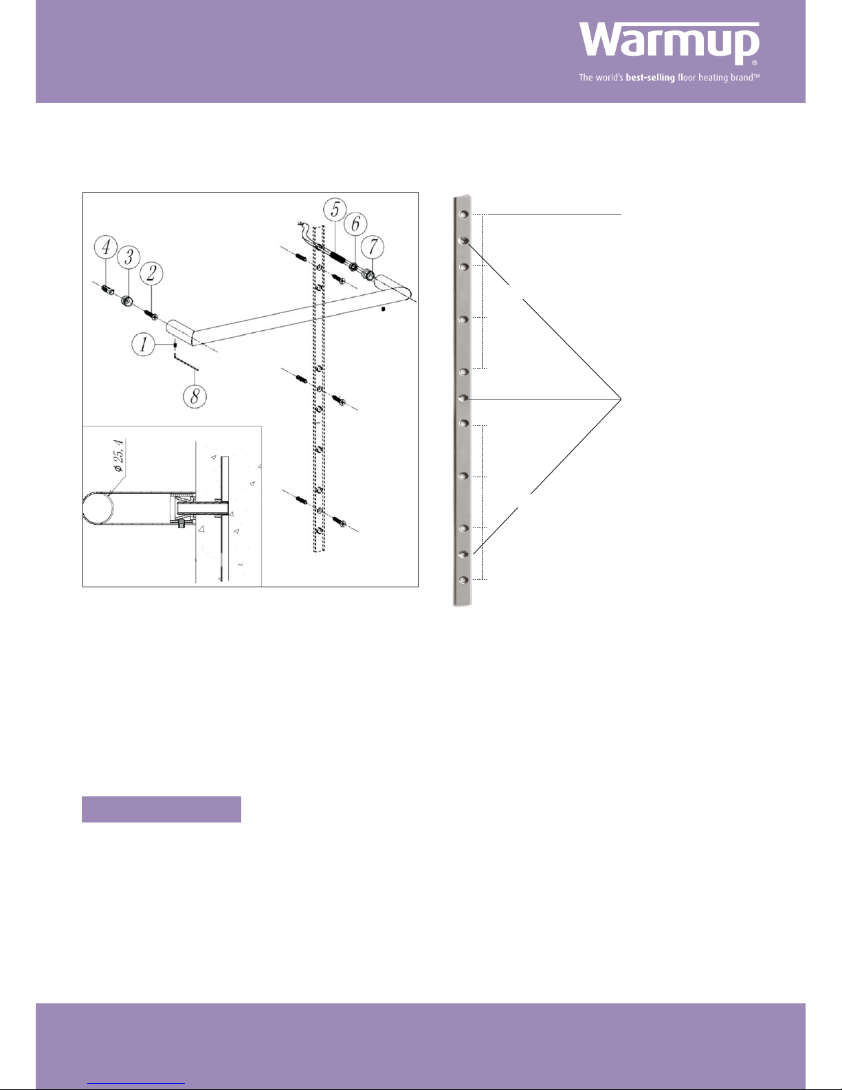
• The heated towel warmer should be mounted vertically with the cord exiting from the base; it should be positioned
at least 600mm/2 feet above the oor.

5
4
TOWEL WARMER INSTALLATION INSTRUCTIONS
Apply junction box if
required by code.
Power cord entry
Align left side to studs
POSITIONING YOUR TOWEL WARMER
MOUNTING YOUR TOWEL WARMER
Do note that all models will have the power cord exiting on the bottom right bracket (when facing the towel warmer
mounted on the wall). Plan accordingly when setting up switches and electrical rough-in.
Select a desired position to mount the towel rail i.e. at least 600mm/2 feet
above the oor and 300mm/1 foot away from all permanent xtures in the
surrounding area (toilet, vanity, etc).
The left side of your towel warmer most be anchored into a stud. Use a
stud-nder tool to locate the 2x4 behind your drywall and mark it with a
pencil. Hold your towel warmer level at the desired height and line it up
with the stud on the left hand side.
Using a pencil, draw around the end of each tube to mark their positions
on the wall. Make sure your marks are level and square as these will
determine where you will secure the device to the wall.
Screenshot of the Youtube video “Installing a Warmup Towel Warmer - 5 Contractors Tips by Warmup”.
Screw the mounting inserts securely to the wall at the locations marked. Press the towel warmer onto the mounting inserts
gradually, checking that each leg is lined up with the mounting inserts before applying force. Mount the towel warmer with a
single grub screw on each of the 4 brackets.

TOWEL WARMER INSTALLATION INSTRUCTIONS
6
If you choose to locate the J-box elsewhere than at the recommended bottom right of the towel warmer, follow the instructions
below. You can also wire it directly into the switch box where you control your towel warmer, or into the box where your Warmup
4iE thermostat is mounted. Please ensure you comply to all local and national code requirements in regards to line voltage wire in
conduit. State and local regulations vary (ex conduit, rigid conduit or neither) and must be respected to avoid electrical hazards.
1. Mount the concealed cable mushroom into the wall where the lower right hand bracket will be located (lower right as you
look at the mounted towel warmer on the wall)
2. Ensure you have a code compliant connection between the mushroom anchor and your electrical connection in the J-box.
3. Determine the other 3 anchor points and secure the wall anchors accordingly.
4. You must ensure that the left side of the towel warmer is secured to wood or metal studs or a structural element.
5. Your lead wire is 6ft long (except models TW001 and TW002 where it is 3ft). You can trim it to your needs leaving no less than
12” outside of the towel warmer.
6. Remove the cover plate from the lower right hand bracket.
7. Sleeve the cable through the wall anchor mushroom and sh it through to your electrical connection. All electrical connections
and wiring must be compliant with local and national electrical codes. Please check with a licensed electrician.
8. Finally safely push your towel warmer into place and tighten the grub screws underneath each bracket.
CONCEALED CORD ENTRY WITH REMOTE J-BOX
1. Refer to the “Mounting your towel Warmer” section to identify exact location of the brackets.
2. The lower right bracket of your towel warmer will come supplied with a box cover plate that covers a standard 2x4 “single
gang” electrical box.
3. To connect your towel warmer, rst wire the power connection cord to the supplied 120V power in the J-box.
a) Always ensure the power is turned off at the breaker box to avoid electrical shock.
b) You can trim the power cord to your needs leaving no less than 12” exiting the towel warmer.
c) Upon secure connection to the line voltage, mount the towel warmer to the brackets and secure by tightening the grub
screws underneath each bracket.
CONCEALED CORD ENTRY WITH ATTACHED J-BOX
a) If your J-box is already located and supplied by the electrician, use that as the main point to determine where the other
3 brackets will fall. You must ensure that the left side of the towel warmer is secured to wood or metal studs or a
structural element.
b) If your J-box is not yet roughed-in, mark the space of the cover plate on the wall to determine the exact location.

7
6
TOWEL WARMER INSTALLATION INSTRUCTIONS
FOR MODELS TW001 AND TW002
MOUNTING INSTRUCTIONS
Mounting bracket to secure
towel bars on the right side
Align left side to studs
Remove drywall section
to mount towel warmer
All bars are right-hand hard wired connections. This means the left side of your horizontal bars will need to line up on a
stud. Use a stud-nder to locate the stud and mark the placement of the towel warmer with a pencil. Then proceed as
above with cutting out the drywall for mounting.
Your TW001 or TW002 bars will be supplied with a mounting rail. This mounting rail will be secured on the right hand side
of the rails (right side when facing the towel warmer on the wall).
The single bar rails are individual heated bars installed horizontally in a ‘landscape’ direction, one on top of the other to
create an aesthetic oating ‘ladder’ feature in the bathroom. The installation of this model requires access behind the
drywall and should be completed before hanging drywall. In other instances, mark the placement of the towel warmer
and cut out the drywall at least 6” wider around the towel warmer. Remove the drywall cutout from the wall and proceed
with mounting instructions below.
Stud
Mount 4 towel bars at 160mm spacing (6-1/2”) or up to 8 bars at 80mm spacing (3-1/4”). To connect up to 8 bars at
6-1/2” spacing, mount two mounting brackets. Warmup will supply you with one bracket with each set of 4 towel bars.
While not recommended, you can trim the mounting bar if required (for example, if using less than 4 bars). The maximum
spacing between the top bar and the bottom bar would be 60”. The leads exiting each bar are 3ft. You would have to make
provisions to ensure the leads connect centrally to a junction box.
Power cord entry on the right side

TOWEL WARMER INSTALLATION INSTRUCTIONS
8
With TW001 and TW002 models, the j-box or connection point will be located away from the bottom right of your towel warmer.
This can either be near the appliance or directly into a switch box or gang box hosting your Warmup 4iE controller (optional).
Do note that the leads exiting each bar are 3ft in length. Do not extend these leads in the wall outside of a code compliant junction
box. It is not safe to make electrical connections outside of a junction box.
Please ensure you comply to all local and national code requirements in regards to line voltage wire in conduit. State and local
regulations vary (ex conduit, rigid conduit or neither) and must be respected to avoid electrical hazards.
The installation of this model requires access behind the drywall and should be completed before hanging drywall. In other
instances, mark the placement of the towel warmer and cut out the drywall at least 6” wider around the towel warmer.
Remove the drywall cutout from the wall and proceed with mounting instructions below:
1. Mount the concealed cable mushroom into the wall where the lower right hand bracket will be located
(lower right as you look at the mounted towel warmer on the wall)
2. Ensure you have a code compliant connection between the mushroom anchor and your electrical connection in the j-box.
3. Determine the other anchor points and secure the wall anchors accordingly.
a) This will be specically identied by the location of the mounting bracket bar secured to the back of the drywall panel
4. You must ensure that the left side of the towel warmer is secured to wood or metal studs or a structural element.
5. Your lead wires are 3ft leaving each bar. You can trim it to your needs leaving no less than 12” outside of the towel warmer
6. Sleeve the cables through the wall anchor mushrooms and sh them through to your electrical connection. All electrical
connections and wiring must be compliant with local and national electrical codes. Please check with a licensed electrician.
7. Finally safely push your towel bars into place and tighten the grub screws underneath each bracket.
CONCEALED CORD ENTRY WITH REMOTE J-BOX
Your package includes:
1
4
2
5
3
6
7
x1
x1
x3
x1
Mushroom kit with
screw and washer

9
8
TOWEL WARMER INSTALLATION INSTRUCTIONS
Any heated towel warmer that is found to be defective due to substandard materials and/or workmanship within 3 years
of purchase will be replaced. To make a claim under this warranty, contact Warmup at (888) 927-6333. Your claim will be
assessed based on the information you provide. You will be required to return the defective product for assessment at your
cost. Register your warranty online: http://www.warmup.com/register-warranty.
This warranty does not cover any installation or removal costs. The warranty does not extend to any consequential loss,
damage, misuse, neglect, alteration or incorrect installation. Items that have been cleaned with anything other than
approved cleaners will not be replaced. Attach your proof of purchase and keep in a safe place with this warranty form.
You must have your proof of purchase for your warranty to be valid.
PRODUCT WARRANTY
8 Holes to mount towel bars
3 Holes to secure to drywall
80mm
80mm
80mm
80mm
80mm
80mm

TOWEL WARMER INSTALLATION INSTRUCTIONS
10
N(White)1.8m
L(Black)1.8m
E(Green)1.8m
N(White)1.8m
L(Black)1.8m
E(Green)1.8m
CODE TUBE SHAPE BARS FINISH VOLTAGE AMPERAGE RESISTANCE
TW082 Square 5 Polished Stainless 120V 0.5A 240Ω
CODE TUBE SHAPE BARS FINISH VOLTAGE AMPERAGE RESISTANCE
TW081 Square 4 Polished Stainless 120V 0.5A 240Ω

11
10
TOWEL WARMER INSTALLATION INSTRUCTIONS
1200
400
1200
267.7
1076.7
153.3
953.3
1200
115.4
22
25.4
400
115.4
N(White)1.8m
L(Black)1.8m
E(Green)1.8m
CODE TUBE SHAPE BARS FINISH VOLTAGE AMPERAGE RESISTANCE
TW080 Square 4 Polished Stainless 120V 0.67 180Ω

TOWEL WARMER INSTALLATION INSTRUCTIONS
12
N(White)1.8m
L(Black)1.8m
E(Green)1.8m
N(White)1.8m
L(Black)1.8m
E(Green)1.8m
CODE TUBE SHAPE BARS FINISH VOLTAGE AMPERAGE RESISTANCE
TW090 Round 6 Polished Stainless 120V 0.5A 240Ω
CODE TUBE SHAPE BARS FINISH VOLTAGE AMPERAGE RESISTANCE
TW091 Round 6 Polished Stainless 120V 0.5A 240Ω

13
12
TOWEL WARMER INSTALLATION INSTRUCTIONS
N(White)1.8m
L(Black)1.8m
E(Green)1.8m
CODE TUBE SHAPE BARS FINISH VOLTAGE AMPERAGE RESISTANCE
TW092 Round 9 Polished Stainless 120V 0.75A 160Ω

TOWEL WARMER INSTALLATION INSTRUCTIONS
14
N(White)1.8m
L(Black)1.8m
E(Green)1.8m
N(White)1.8m
L(Black)1.8m
E(Green)1.8m
CODE TUBE SHAPE BARS FINISH VOLTAGE AMPERAGE RESISTANCE
TW107 Square 7 Brushed Stainless 120V 0.67A 180Ω
CODE TUBE SHAPE BARS FINISH VOLTAGE AMPERAGE RESISTANCE
TW110 Square 10 Brushed Stainless 120V 1.0A 131Ω

15
14
TOWEL WARMER INSTALLATION INSTRUCTIONS
N(White)900mm
L(Black)900mm
E(Green)900mm
N(White)900mm
L(Black)900mm
E(Green)900mm
CODE TUBE SHAPE BARS FINISH VOLTAGE AMPERAGE RESISTANCE
TW001 Round 1-4 Polished Stainless 120V 0.25 1600Ω
CODE TUBE SHAPE BARS FINISH VOLTAGE AMPERAGE RESISTANCE
TW002 Square 1-4 Brushed Nickel 120V 0.25 1600Ω

us@warmup.com I ca@warmup.com
This manual suits for next models
9
Table of contents
Popular Food Warmer manuals by other brands

Presto
Presto Nomad Mason Jar instructions

Linea 2000
Linea 2000 DOMO DO636K Instruction booklet

Parker Laboratories
Parker Laboratories Thermasonic Series operating instructions

Amba
Amba RS 545008-S2121B Instructions for use and installation

Hatco
Hatco Glo-Ray GRKW-1 Specifications

HURAKAN
HURAKAN HKN-RH1 manual

Cres Cor
Cres Cor Banquet Warming Cabinet CCB150 Series Operating and maintenance instructions

Buffalo
Buffalo DB455 instruction manual

Buffalo
Buffalo DC858 instruction manual

Cres Cor
Cres Cor CCB-120A Operating and maintenance instructions

Server Products
Server Products FS-4 PLUS manual

Broil King
Broil King MLB-25P Use & care manual