Warmup tempo ELT-01-XX-01 User manual

User Guide

2
Pack Contents
Contents
Safety Information................................................................................................. 3
Step 1 - Installation................................................................................................ 3
Step 2 - Wiring Connections................................................................................. 4
Wiring Connections - Loads over 16 amps...........................................5
Step 3 - Thermostat Mounting............................................................................. 6
Welcome to the tempo thermostat ..................................................................... 7
Programming ......................................................................................................... 9
Installer settings...................................................................................................12
Troubleshooting ..................................................................................................14
Technical Specications ......................................................................................15
Warranty ...............................................................................................................16
1
2
3
4
x1 x1 x2 x1

3
1
2
3
4
Safety Information
Step 1 - Installation
The thermostat must be installed by a qualied electrician. It requires a
permanent 230 V AC supply from a 30mA RCD or RCBO protected circuit
in accordance with the current edition of the BS7671 Wiring Regulations.
Isolate the thermostat from the mains supply throughout the
installation process. Ensure that wires are fully inserted into the terminals
and secured, free strands should be trimmed, as they could cause a
short-circuit.
Install the thermostat in an area with good ventilation. It should not be
beside a window/door, in direct sunlight or above another heat generating
device (e.g. radiator or TV).
The supply to the thermostat must come from a ≤16A MCB, RCBO, or Fuse
to protect it and the heater from overloading.
q
q
q
q
For bathroom installations the thermostat MUST be mounted outside
of Zones 0, 1 and 2. If this is not possible then it must be installed in an
adjacent room, controlling the rooms using the oor sensor only.
The thermostat and its packaging are not toys; do not allow children
to play with them. Small components and packaging present a risk of
choking or suocation.
The thermostat is suitable for indoor use only. It must not be exposed
to moisture, vibrations, mechanical loads or temperatures outside of its
rated values.
For safety and licensing reasons (CE/UKCA), unauthorised change and/or
modication of the thermostat is not permitted.
q
q
q
q
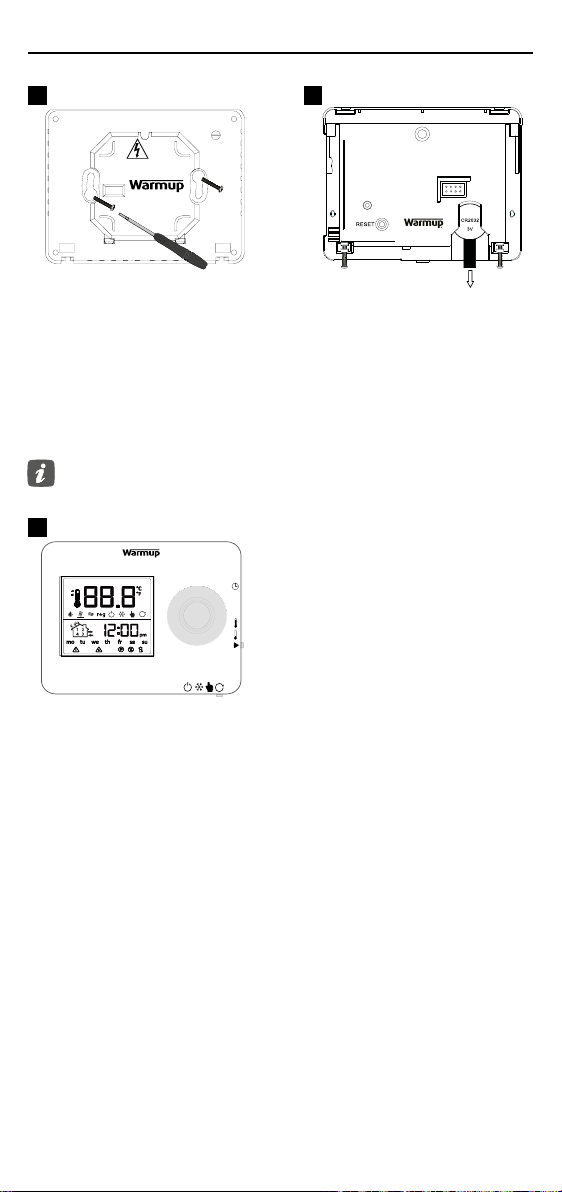
Isolate the thermostat supply from
the mains supply.
Install a minimum 35 mm deep
electrical back box in your preferred
thermostat location. Pull wires
(heater, supply and oor sensor)
through back box and complete
terminal wiring.
Unclip the front housing from the
power module.
Release the front housing as
shown.
1
3
2
4
230 V AC:
50Hz Heaters. Max. 16A
(3,680W)
Sensor
1
2

4
Step 2 - Wiring Connections
WARNING!
The thermostat must be installed by a qualied electrician in accordance with
the current edition of the BS7671 Wiring Regulations.
NOTE: For loads above 10 A, the conductor wire gauge should be at least
2.5mm²
4
Electric Underoor Heating
Supply Live and Neutral
Floor heating Neutral and Live
Max. 16A (3680W)
Hydronic Underoor Heating
Supply Live and Neutral
Terminal 4 - Not Used
Terminal 5 - Switched Live to Wiring Centre
Central Heating
Supply Live and Neutral
Terminal 4 - Not Used
Terminal 5 - Switched Live to zone valve / boiler
For extra low voltage or volt-free systems a contactor must be used.
Connecting the tempo directly to extra low voltage or volt-free boilers may
cause damage to the boiler circuit.
Sensor Connection
7 & 8 Floor Sensor (No Polarity)
Fil Pilote
1 F.P Connect to Fil Pilote (F.P.) France Only

5
Step 2 - Wiring Connections - Loads over 16 amps
Warmup thermostats are rated for a maximum of 16 amps (3680 W). A
contactor must be used to switch loads exceeding 16 amps. Please see wiring
diagram below.
4
30 mA
≤16A
30 mA
≤16A
R
Snubber
C
L N PE
L N PE
PE
L
N

6
1
2
3
4
Step 3 - Thermostat Mounting
Insert xing screws through
mounting holes of the power
module and tighten.
Re-attach the front housing. You
can now power up the thermostat.
1
3
tempo
element
series
TM
exclusivelyfrom
+
Locate your CR2032 3-Volt lithium
battery on the reverse of the
front housing. Remove the plastic
strip from under the battery. The
battery should always be installed
with positive side “+” facing
outwards.
2
Disconnect the power supply before replacing the battery. Only
use the same type of battery as listed in this manual.

7
Welcome to the tempo thermostat
Icons on tempo
1Rotary control
Rotate left/right to change increment
2Rotary button
3Program slider
4Mode slider
5Reset button
On reverse of the front housing
Standby
The thermostat is in standby mode and will not target any temperature. It is still
connected to mains electricity and your heating system is not isolated. Always isolate
from the mains before undertaking any maintenance.
Frost protect
The thermostat will not let the temperature fall below 5°C (41°F)
Manual mode
The thermostat will hold a xed temperature. Just turn the rotary control to change
the target temperature.
Program mode
In this position your thermostat will run the program you have set.
If you would like to temporarily adjust the temperature, just turn the rotary control.
This will set a temporary override and will hold a xed temperature until the next
scheduled program period.
* Periods 2 & 4 are the start times of the “Setback” temperature. The “Setback”
temperature is a lower energy ecient temperature when outside of a heating period.
If you do not require the heating on then set the setback temperature to 5°C.
1
2
3
4
Set time / day
1
2
3
4
Period 1 - Heating ON
Period 2 - Setback*
1
2
3
4
Period 3 - Heating ON
Period 4 - Setback*
1
2
3
4
Comfort temperature
1
2
3
4
Setback temperature
1
2
3
4
Run
1
2
3
4
1
2
3
4
1
4
3
2
The Tempo has been designed with simplicity in mind and is highly intuitive
in its programming. The sliders and simple rotary control make the setting of
the thermostat quick and easy.

8
Display icons
1
2
3
4
1
2
3
4
Current oor/Air temperature
Will also temporarily show set
temperature
1
2
3
4
Clock
1
2
3
4
Celsius/Fahrenheit Period 1 - Heating ON
1
2
3
4
Program mode Period 2 - Setback
1
2
3
4
Manual mode Period 3 - Heating ON
1
2
3
4
Frost protect Period 4 - Setback
1
2
3
4
Standby
1
2
3
4
-
1
2
3
4
Day of the week
1
2
3
4
Regulator mode
1
2
3
4
Floor sensor error
1
2
3
4
Air mode Displays when overheat
limit is reached
1
2
3
4
Floor mode
1
2
3
4
Fil Pilote
1
2
3
4
Heating indicator
1
2
3
4
No mains electricity available
1
2
3
4
Displays when COMFORT -1/
-2 is target temperature
When l pilote is activated
1
2
3
4
Battery needs to be replaced
When the thermostat displays both the manual and program
icon the thermostat is in a manual override and will hold a xed
temperature until the next scheduled program period.
In both manual and program modes, when setting a target
temperature or a temporary override, if the rotary control is not
moved for 3 seconds the temperature will ash once and revert
to displaying current air/oor temperature

9
Programming
How to set into Manual Mode
Setting into manual mode allows you to set a xed target temperature for
the thermostat to achieve. The thermostat will continue to maintain this
temperature until another operating mode or temperature is selected.
• Move the mode slider to the
manual mode icon “ ”.
• Ensure the program slider is in the
run position “
1
2
3
4
”.
• Move the mode slider to the
program mode icon “ ”.
• Move the program mode slider to
the set time / day icon “
1
2
3
4
”.
• Turn the rotary control clockwise/
anti-clockwise to increase or
decrease the target temperature
• To set the current time, turn
the rotary control clockwise /
anti-clockwise.
• To set the current day of the week,
press the rotary button and then
turn the rotary control.
How to set a program
Setting a program allows you to set comfort temperatures at set times
throughout the day. The tempo allows for 2 heating schedules to be set.
Days can programmed individually (7-day), all days the same (1-Day) or
weekdays as a block and weekends as a block (5-2), the choice is yours.
1
2
3
4
1
2
3
4
1
2
3
4
1
2
3
4
The tempo is defaulted to (5-2). This setting can be changed when the
program slider is on set time / day icon “
1
2
3
4
” and then pressing and
holding the rotary button for 5 seconds.
12
12
Moving the program slider to the next position saves the values you
have entered.

10
How to set a program
• Move the program slider to “1”.
• Turn the rotary control to set the
start time for “Period 1 - Heating
ON” for Mon-Fri.
• Move the program slider to “2”.
• Turn the rotary control to set the
start time for “Period 2 - Setback”
for Mon-Fri.
• Press the rotary button to
program “Period 1 - Heating ON”
for Sat-Sun.
• Turn the rotary control to set the
start time for “Period 1 - Heating
ON for Sat-Sun”.
• Press the rotary button to
program “Period 2 - Setback” for
Sat-Sun.
• Turn the rotary control to set the
start time for “Period 2 - Setback”
for Sat-Sun.
1
2
3
4
1
2
3
4
1
2
3
4
1
2
3
4
3
5
4
6
Move the slider to “3” and then “4”, repeating steps 3 - 6 above for
periods 3 & 4.
If you require one heating schedule then set the start times of periods
2 and 3 the same. Periods 1 and 4 will then be your Heating ON and
Setback times.
If you press and hold the rotary button for 3 seconds it will copy the
start time to the next day.

11
• Move the program slider to the
comfort temperature icon “
1
2
3
4
”.
• Turn the rotary control to set the
desired comfort temperature.
• Move the program slider to the
run icon “
1
2
3
4
”.
• The thermostat will now run your
programmed heating schedule.
• Move the program slider to the
setback temperature icon “
1
2
3
4
”.
• Turn the rotary control to set the
desired setback temperature.
1
2
3
4
1
2
3
4
5 6
How to set a program
Comfort temperatures will run on Periods 1 and 3 - Heating ON
Setback temperatures will run on Periods 2 and 4 - Setback
The “Setback” temperature is a lower energy ecient temperature
when outside of a heating period.
1
2
3
4
7

12
Installer settings
Installer settings should be set by the installer of the thermostat and are
unlikely to need changing during the product’s life. If it is necessary to enter
installer settings, follow the steps below.
1
2
3
4
1 2
• Ensure there is power going to the
thermostat.
• Remove the front housing from
the power module.
• Press and Hold the rotary button
whilst re-attaching the front
housing to the power module.
Once you have entered the installer settings, turn the rotary control
to change your selection and press the rotary button to accept and
proceed to the next step. Once you have completed all the steps you
will automatically exit the installer setting mode.
#Setting congured Default Display
1Change clock format
(12hr / 24hr)
24H
2Change unit of
temperature
measurement
(°C / °F)
°C
3Temperature target
Floor/ Air/ Regulator
In regulator mode the
thermostat will run
for a set number of
minutes in a 10 minute
cycle.
Floor
4Set Floor Sensor Type
(NTC10K / NTC12K)
Current Warmup
thermostats use
NTC10K sensor probes.
Some older Warmup
thermostats used
NTC12K sensor probes.
10K
5Adaptive Learning
(ON/OFF)
Adaptive learning
calculates the optimum
heating start time in
order to reach the
comfort temperature at
the start of the comfort
period. Program mode
only.
On

13
#Setting congured Default Display
6Fil Pilote (France only)
The thermostat can
obey the 6 standard
commands of l pilote
(pilot wire)
O
7Set an overheat limit
to protect your oor
Overheat temperature
is measured by Floor
Sensor and can be set
between 25 - 40°C. If
“Overheat” temperature
is reached then heating
is suspended for 5
minutes
30°C
Maximum Overheat Limits
Tiles 40°C / 104°F
Stone 40°C / 104°F
Wood/Laminate 28°C / 86°F
Carpet 28°C / 86°F
Vinyl 28°C / 86°F
8Set an oset value
(-9 /+9°C)
Calibrate the
temperature reading of
your thermostat sensors
0°C
9Set the maximum duty
cycle length between
2-10 minutes per 10
minute cycle.
NOTE: Option only
available if Installer
Step 3 is switched to
Regulator (REG) Mode.
10
Installer settings

14
Display is blank (Electrician Required) Electrician required to verify power is
going to the thermostat and that it is correctly wired.
The thermostat is
not controlling the
temperature
Ensure that the program slider is in the run position ”
1
2
3
4
”
(lowest point) and that the mode slider control (bottom) is in
the manual “ “ or program “ “positions.
Heating is coming
on earlier than
programmed times
Adaptive learning calculates the optimum heating start time
in order to reach the comfort temperature at the start of
the comfort period. It will only work in Program Mode. See
installer setting #5.
Floor sensor error
“
1
2
3
4
” / “ --- ”
(Electrician Required) Electrician required to verify that the
oor sensor has been wired correctly. If it is correctly wired
the electrician will need to check the resistance of the oor
sensor using a multi-meter. For temperatures between 20°C
- 30°C the resistance of the oor sensor should measure
between 8K ohms and 12K ohms.
If the electrician nds a fault, and the thermostat is in the
room to be heated then it can be set into “Air Mode”.
To set into “Air Mode” or “Regulator Mode”, see installer
setting #3.
If “---” still remains when set into air mode the thermostat
will have to be replaced.
Overheat “ “ If you see the overheat icon this means that your oor has
become too hot and the heating has been suspended. See
installer setting #7.
Low battery “
1
2
3
4
”The low battery icon will display when the coil-cell CR2032
3-volt lithium battery needs to be replaced. The thermostat
must be connected to the mains electricity supply in order
to work, it is not designed to be used with an intermittent
power supply. If the battery is not installed then your
thermostat will not be able to maintain the clock time if
power is lost.
Incorrect calibration Your thermostat should not need any calibration, however if
you would like to apply an oset to the temperature settings
see the installer setting #8.
No mains electricity
“
1
2
3
4
”
(Electrician Required) The thermostat is not receiving
power. Check the thermostat power module is properly
installed and that there is 230V mains electricity supply
connected.
Regulator mode (Reg)
is displayed
In this mode your thermostat will come on for a set number
of minutes in a 10 minute cycle. The thermostat will not use
the temperature for control.
Fil Pilote (FP) is
displayed
The thermostat can obey the 6 standard commands of l
pilote (pilote wire), (France only).
HI or LO is displayed The thermostat will display “HI” if the ambient temperature
exceeds 40°C (104°F) and “LO” when the ambient
temperature falls below 0°C (32°F).
Troubleshooting

15
Instructions for Disposal
Do not dispose of the device with regular domestic waste!
Electronic equipment must be disposed of at local collection points
for waste electronic equipment in compliance with the Waste
Electrical and Electronic Equipment Directive.
Technical Specications
Waste batteries must be removed from the device and disposed of
separately in line with local environmental regulations. Always disconnect the
thermostat from the mains supply before removing the battery.
If there is leakage from the battery, wear butyl rubber gloves and carefully
collect the battery and place in a plastic container for disposal. Remove any
spilled liquid with an absorbent material and contain for disposal.
Model ELT-01-XX-01
Operating Voltage 100-240V +/- 15%; 50/60Hz
Protection Class Class II
Max. Load 16 A (3680 W)
Rated impulse voltage 4000 V
Battery Replaceable Coin Cell CR2032
Automatic action 100,000 cycles
Disconnection means Type 1B
Pollution degree 2
Max. Ambient Temperature 0 - 40 °C
Relative Humidity 80 %
IP Rating IP20
Dimensions 90 x 113 x 23 mm
Screen size 45 x 50 mm
Sensors Air & Floor (Ambient)
Sensor Type NTC10k 3m Long (Can Be Extended To 50 m)
Installation Depth Recommended: 50 mm Back Box
Minimum: 35 mm Back Box
Compatibility
Electric, Hydronic Underoor Heating.
Max. 16A (3680W)
Central Heating Systems
(Combi & system boilers with switch live, 230V AC input)
Er-P Class IV
Warranty 3 years
Approvals BEAB

16
Warmup plc warrants this product, to be free from defects in
the workmanship or materials, under normal use and service,
for a period of three (3) years from the date of purchase by
the consumer. If at any time during the warranty period the
product is determined to be defective, Warmup shall repair or replace it, at
Warmup’s discretion.
If the product is defective, please either,
(i) return it, with a bill of sale or other dated proof of purchase, to the place
from which you purchased it, or
(ii) contact Warmup. Warmup will determine whether the product should be
returned, or replaced.
This warranty does not cover removal or reinstallation costs, and shall not
apply if it is shown by Warmup that the defect or malfunction was caused by
damage which occurred while the product was in the possession of the end
user. Warmup’s sole responsibility shall be to repair or replace the product
within the terms stated above.
WARMUP SHALL NOT BE LIABLE FOR ANY LOSS OR DAMAGE OF ANY KIND,
INCLUDING ANY INCIDENTAL OR CONSEQUENTIAL DAMAGES RESULTING,
DIRECTLY OR INDIRECTLY, FROM ANY BREACH OF ANY WARRANTY,
EXPRESSED OR IMPLIED, OR ANY OTHER FAILURE OF THIS PRODUCT. THIS
WARRANTY IS THE ONLY EXPRESS WARRANTY WARMUP MAKES ON THIS
PRODUCT. THE DURATION OF ANY IMPLIED WARRANTIES, INCLUDING
WARRANTIES OF MERCHANTABILITY AND FITNESS FOR A PARTICULAR
PURPOSE, IS HEREBY LIMITED TO THE THREE-YEAR DURATION OF THIS
WARRANTY.
This warranty does not aect your statutory rights.
3YEAR
LIMITED
WARRANTY
W
A
R
M
U
P
3
Y
E
A
R
W
A
R
R
A
N
T
Y
W
A
R
M
U
P
3
Y
E
A
R
W
A
R
R
A
N
T
Y
Warranty

Warmup plc n704 Tudor Estate nAbbey Road nLondon n NW10 7UW n UK
Warmup GmbH nOttostraße 3 n27793 Wildeshausen nDE
Warmup plc
www.warmup.co.uk
T: 0345 345 2288
F: 0345 345 2299
Warmup - OM - Tempo_ELT-01 - V1.8 2023-02-13_EN
Table of contents
Other Warmup Thermostat manuals

Warmup
Warmup WA-XSTAT-V User manual

Warmup
Warmup Terra User manual

Warmup
Warmup UCCG Installation manual

Warmup
Warmup konekt WIRELESS KW-STATH User manual

Warmup
Warmup WP-207-F User manual

Warmup
Warmup Luxury 2 LUXY2D44 User manual

Warmup
Warmup + Kit User manual

Warmup
Warmup 3IE User manual

Warmup
Warmup 3IE User manual

Warmup
Warmup 4iE WiFi User manual

Warmup
Warmup W3115DT AU User manual

Warmup
Warmup 4iE WiFi User manual

Warmup
Warmup 4iE WiFi User manual

Warmup
Warmup WA-XSTAT User manual

Warmup
Warmup TH115 A User manual

Warmup
Warmup WA-TSTAT-V User manual

Warmup
Warmup 3IE User manual

Warmup
Warmup 6iE User manual

Warmup
Warmup 3IE User manual

Warmup
Warmup 6iE User manual