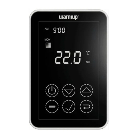
Warmup Portrait 4iE Installation instructions

4iE Portrait
Installation & Operating Manual
(WiFi & Non-WiFi)
For technical help:
US: (888) 927-6333
CA: (888) 592-7687
warmup.com
warmup.ca

2
Contents
Pack Contents .......................................................... 3
Mounting/Positioning.................................................. 4
Wiring Connections .................................................... 5
Assembling the 4iE..................................................... 9
4iE Portrait Setup - WiFi Version
Getting Started......................................................... 10
Registration............................................................. 11
4iE Portrait Setup - Non-WiFi Version
Non-WiFi Initial Setup................................................. 13
Welcome ................................................................ 14
Programming............................................................ 15
Settings.................................................................. 19
Troubleshooting ........................................................ 20
Important Notices...................................................... 23
Technical Specications............................................... 25

Back PlateThermostat Face Floor Sensor
3
IMPORTANT INFORMATION: Installation should only be carried
out by a qualied and competent electrician and must conform
to local electrical code. Conduits are only required where it
is mandated by state or provincial code. Please refer to local
electrical code for compliant applications.
The 4iE and its power supply should be isolated from
the mains supply throughout the installation process.
Pack Contents

Mounting/Positioning
4
Loosen both screws to
the left of the 4iE and
remove the Back Plate.
Install square 2 3/4” deep
back box with a single
mud ring (also called
plaster ring) in your
preferred thermostat
location.
4iE Portrait
Step 1 - Install Back Plate
1
Before making any permanent xtures Warmup recommends
identifying your preferred location for the 4iE. It should be
located in an area with good ventilation. It should not be beside a
window/door, in direct sunlight or above another heat generating
device (e.g. radiator or TV).
For the WiFi enabled 4iE, ensure the distance from your router to
the 4iE is not too great. This will reduce the risk of signal strength
and interference issues.
Faceplate
Thermostat
Trim plate
Mount faceplate vertically
Deep double-gang box recommended
Drywall
2

Wiring Connections
5
4iE Portrait
Step 2 - Wiring Connections
!Isolate the thermostat from the mains supply
throughout the installation process
Heating Load connected to 4iE - Max. 15 Amps
N.B. Input voltage 120V (Hot/Neutral) or
240V (Hot/Hot). Device is dual
voltage capable.
L1-LOAD-L2
L1-LINE
L2
12 3
EXT
FLOOR SENSOR
(NO POLARITY)
L1-LOAD-L2
HEATING
(MAX 3600W/
15 Amps)
L1-LINE-L2
POWER
SUPPLY
L2-LINE
HOT (120V)
SUPPLY WITHOUT GFCI
PROTECTION
NEUTRAL (120V) OR
HOT (240V)
Heater/s
Max 15A
L1-LINE
This is the most common connection

Wiring Connections
6
4iE Portrait
Step 2 - Wiring Connections
240V SUPPLY WITHOUT GFCI
PROTECTION
L2-LINE
Hot (240V)
Hot (240V)
L1-LINE
240V GFCI
PROTECTED
SUPPLY
240V
COIL SUPPLY
N.B. All heating loads connect to Relay-25
only, controlled by 4iE
L1-LOAD-L2
L1-LINE
L2
12 3
EXT
FLOOR SENSOR
(NO POLARITY)
L1-LOAD-L2
HEATING
(MAX 3600W/
15 Amps)
L1-LINE-L2
POWER
SUPPLY
Hot (240V)
Hot (240V)
0 1
8642
Heater/s
Max 25A
Heating Load connected to Relay 25 - Max. 25 Amps

Wiring Connections
7
4iE Portrait
Step 2 - Wiring Connections
240V SUPPLY WITHOUT GFCI
PROTECTION
L2-LINE
Hot (240V)
Hot (240V)
L1-LINE
240V GFCI
PROTECTED SUPPLY
Hot (240V)
Hot (240V)
L1-LOAD-L2
L1-LINE
L2
12 3
EXT
FLOOR SENSOR
(NO POLARITY)
L1-LOAD-L2
HEATING
(MAX 3600W/
15 Amps)
L1-LINE-L2
POWER
SUPPLY
0 1
8642
Heater/s
Max 25A
Heater/s
Max 15A
240V
COIL SUPPLY
N.B. Heating loads connect to Relay-25
and 4iE:
Relay-25 Max load 25A
4iE Max load 15A
Total Max load 40A
Heating Load connected to 4iE and Relay 25 - Max. 40 Amps
For Larger installations

Wiring Connections
8
4iE Portrait
Step 2 - Wiring Connections
Master/relay function: Used to control loads greater than 15A.
Heaters will be split across two 4iE’s, one being the master and
the other being the relay (slave). Only one oor sensor is required,
wired into terminals 1 & 2 of the Master 4iE.
Wiring Connections: Use low voltage electrical cables to link
terminals 2 & 3 of the Master and Relay.
Thermostat Setup: Settings > Adv. settings > Heater setting > Ext
output
NOTE: Set the relay 4iE to relay rst.

4iE Portrait
Step 3 - Reattach 4iE Face
Reattach the 4iE face to the
Back Plate and tighten both
screws to secure. You may
now restore power to the
thermostat and begin setup.
1
7
Assembling the 4iE
9

Getting Started
10
Depending on who has installed your 4iE, you will have one of
the following screens visible. If you have anything other than the
screens below, please press the standby button on the underside of
Thermostat Face.
Steps 4 to 6 are specic to the WiFi enabled version of the 4iE. For
setup of the Non-WiFi version of the 4iE see page 13.
Language
If you have this
screen present, the
Thermostat has not
been connected to a
WiFi network.
Please follow the
on-screen
instructions to
connect it to WiFi.
No WiFi
If you have this
screen present, the
Thermostat must
be connected to a
WiFi network.
> Settings
> Network
4iE Portrait (WiFi Version)
Step 4 - Getting Started
No Server
If you have this
screen present, the
Thermostat is
connected to a WiFi
network and you
can continue to
device registration.
Registration can be
completed via the
MyHeating App or
by visiting
my.warmup.com.
back accept
Language
english
70
71 un�l 11:30
air
OF
10:48.
.
69 floor
tue 5 jul
70
71 un�l 11:30
air
O
F
10:48.
.
69 floor
tue 5 jul

App Download
The MyHeating App is available for iOS and Android devices via
the App Store or Google Play. If you have not done so already,
download the “MyHeating” App to your tablet or smartphone.
Search ‘MyHeating by Warmup’
Device Number
When rst registering and setting up your location on MyHeating,
you will need the device number of the Thermostat. Your installer
should have recorded it below, if not it can be found in the
Thermostat menu:
> Settings > Advanced settings > About > Info
4iE Portrait (WiFi Version)
Step 5 - Download ‘MyHeating’ App
Go to my.warmup.com or
MyHeang App to complete setup
Your device number is
ok
Registration
11

Registration
12
Below shows the menu structure to follow, when rst registering
with the MyHeating App or my.warmup.com
4iE Portrait (WiFi Version)
Step 6 - Registering your device
Location
A location needs to be setup before a room can be congured and
the 4iE device registered. Creating a location is user friendly and
easy to follow. It is advised to have details of your current energy
tari and pricing to hand, as these will be required for the energy
monitoring features.
Room
With a location now setup, the next step is to register a room.
When creating a new room, you must enter the following
information:
Location (Select the newly setup location)
Room name (Description, e.g. Upstairs Bathroom)
Room type (Select the room type e.g. Bathroom)
Floor type (Select the oor type e.g. Tile/stone)
Device number (See page 11)
System type (Select e.g. ’Electric Underoor’
System power (Size of heat source e.g.1000W)
Power source (Energy source e.g. gas/electricity)
NOTE: Please ensure you enter the correct System Type and Wattage of
heaters connected. If a relay has been installed please set System Type as
Electric + Relay.
Registration
Once the App has been successfully downloaded and device
number recorded you will need to set up your MyWarmup account.
The Thermostat can be registered via the MyHeating App or by
visiting my.warmup.com

4iE Portrait (Non WiFi Version)
13
On initial power up you will have to congure the setup of your
4iE. The settings are detailed below.
Language select your chosen language
System type select your chosen heating system and enter
correct wattage you have connected
Set time manually set time
Set date manually set date
Daylight savings set daylight savings
(europe/n.america/australia/o)
Temperature format fahrenheit/celsius
Home screen style select the theme for your 4iE
Background image select the background image for your 4iE
Display brightness change the screen brightness for normal use and
standby
Audio feedback turn the ‘click’ sound on/o
Heating target control your heating using the oor/air sensor
Heating limits set the temperature limits for your oor type.
User Dened lets you set custom limits
Tari settings select single or standard/low energy tari
Set a program select between, custom, preset & or xed
temperature
Setback Temperature set a lower temperature for the thermostat to
achieve on your “away periods” or set to “o” if
no heating is required.
NOTE: Please ensure you enter the correct System Type and Wattage of
heaters connected. If a relay has been installed please set System Type as
Electric with Relay.
Non-WiFi - Initial Setup

TEST MONTHLY
09:48
82 floor 57
tue 25 apr
78
78 un�l 12:30
air
O
F
14
Welcome
Weather*
* Weather App is only available on Wi-Fi enabled version of the 4iE.
Once setup has been completed the thermostat will display the
home screen. If you do not press any button for 1 minute the 4iE
screen will dim and go into standby. To wake the 4iE just tap the
screen or press the lock icon.
Press the button on the bottom of the device to put the
thermostat in/out of standby mode. Hold the button for 3 seconds
to turn the heating o.
Menu
Date
Time
Air Temperature
Floor Temperature
GFCI Test Button
Target Temperature
Heating Indicator
1
2
8
9
3
4
5
6
7

Programming
15
Custom Program
1
3
2
4
Press menu > Program >
Set program > Set custom
program.
Select days of the week
you wish to program.
Select period 1 to begin
programming. Program the times and
target temperatures of
your custom schedule and
press accept. Repeat for
additional periods.
Setback Temperature - The setback temperature is defaulted to 61°F. To
alter the setback Press Menu > Program > Set setback temperature.
Setting a Custom Program allows you to set comfort temperatures
at set times throughout the day.
back accept
help
saturday
sunday
monday
tuesday
wednesday
thursday
friday
monday
tuesday
wednesday
thursday
friday
back accept
delete
start
temp
end
P1
06:00.
08:00.
70°F
back help
set custom
program
select preset
program
set fixed
temperature
back accept
add period
help
start temp end
06:00.
P1
P2
08:00.
70°F
06:00 08:00
70°F
. .

Programming
16
back help
set custom
program
select preset
program
set fixed
temperature
Preset Program
1 2
Press menu > Program
> Set program > Select
preset program.
Press accept.
Select a Preset Program created by Warmup. See the summary of
the Preset Programs below.
Bathroom Living Room Bedroom Kitchen
Time Temp. Time Temp. Time Temp. Time Temp.
Mon-
Fri 06:00.
08:00.
07:00.
11:00.
72°F
61°F
68°F
61°F
06:00.
09:30.70°F
61°F
06:00.
08:00.
08:00.
11:00.
70°F
61°F
68°F
61°F
06:00.
08:00.
06:00.
10:00.
70°F
61°F
70°F
61°F
Sat-
Sun 07:00.
11:00.
06:00.
11:00.
72°F
61°F
68°F
61°F
08:00.
09:30.70°F
61°F
06:00.
08:00.
08:00.
11:00.
70°F
61°F
68°F
61°F
07:00.
11:00.
06:00.
10:00.
70°F
61°F
70°F
61°F
back accept
help
monday
tuesday
wednesday
thursday
friday
saturday
sunday
back
Select A Preset
bathroom
living room
bedroom
kitchen

Programming
17
Fixed Temperature
Temporary Override
1
1
2
2
Press menu > Program >
Set program > Set xed
temperature.
Press the temperature in
the middle of the home
screen.
Alternatively press menu >
Temperature > Override.
Set the target temperature
and press accept.
Set the target
temperature, duration of
override and press accept.
Set a xed temperature for the thermostat to reach and maintain
until you revert back to program mode or switch the heating o.
Set a temperature you would like the thermostat to reach and the
length of time you want this override to last.
back accept
target
un�l
Override
61°F
15 min
back help
set custom
program
select preset
program
set fixed
temperature
back accept
Fixed Temperature
70°F
70
71 un�l 11:30
air
O
F
10:48.
.
69 floor
tue 5 jul
43

18
Holiday Mode
Frost Protect
1
3
2
4
Press menu > Program >
Holiday mode > Program. Set the holiday start time
and date and press next.
Set the holiday end
time and date and
press next.
Set the holiday target
temperature and press
accept.
back accept
Holiday Temperature
50°F
back next
Start Date
12:00
2018
01
jan
Select Frost Protect to set your heating to a constant 45°F to
protect your home from frost. Press menu > Temperature > Frost
protection.
back next
End Date
12:00
2018
02
jan
Holiday Mode allows you to override your schedule with a lower
xed temperature over a set time to save energy.
back program
Holiday Mode
start date
off
off
end date
Programming

19
Settings
Time
Set time Manually set time
Set date Manually set date
Daylight savings Set daylight savings
(europe/n.america/australia/o)
Heating preference
Temperature format Celsius/fahrenheit
Control air/oor Use air or oor sensor as heating target
Early Start Starts heating early so it’s up to temperature at
the right time
Display/Audio
Background Change the background screen (upload your own
via MyHeating App or by visiting my.warmup.com)
Home screen style Choose a theme for the main screen
Display brightness Change the screen brightness for normal use and
standby
Lock Set a lock code
Audio Feedback turn the ‘click’ sound on/o
Network Choose a WiFi network
Heater Settings
Heating Limits Set the temperature limits for your oor type.
User Dened lets you set custom limits
Regulator Controls the heating in 10 minute cycles. The
number you enter is the number of minutes in
a 10 minute cycle that the heating will be on
Ext Output This allows one thermostat to control another
Probes Set the specication of the probes or set to
‘none’ to hide the probe on the homescreen
Probe application Choose if the oor probe is being used as a Floor
or Amb (ambient) sensor
Oset Set the oset of the sensors to improve accuracy
Reset This will restore all the factory default settings
Advanced Settings

Troubleshooting
20
4iE Portrait
Troubleshooting
1. Check that the display/standby brightness is not on
the lowest settings ‘0’.
2. (Electrician Required) Electrician required to verify
power is going to the 4iE and that it is correctly wired.
1. (Electrician Required) Electrician required to verify
that the oor sensor has been wired correctly. If it is
correctly wired the electrician will need to check the
resistance of the oor sensor using a multi meter. For
temperatures between 68°F and 86°F the resistance of
the oor sensor should measure between 8K ohms and
12K ohms.
If the electrician nds a fault, and the 4iE is in the
room to be heated then it can be set into “Air Mode”.
(Air Mode only suitable for tiled oors if oor sensor has
been damaged)
1. The 4iE “Early Start” function is on. This means
that the heating will come on early to achieve the set
temperature at the set time.
1. Delicate oor coverings need to have their
temperatures limited. If the nished oor is set for
wood, laminate, vinyl etc. you are unable to set the
temperature above 81°F.
Display is blank
“er1” or “er2” is
displayed
Heating is coming on
earlier than the pre-
programmed times
I cannot to set above a
certain temperature
This manual suits for next models
1
Table of contents
Other Warmup Thermostat manuals

Warmup
Warmup tempo User manual

Warmup
Warmup MTC-1991-WU User manual

Warmup
Warmup WA-TSTAT-V User manual

Warmup
Warmup WA-XSTAT User manual

Warmup
Warmup OCC2 User manual

Warmup
Warmup 6iE User manual
Warmup
Warmup 3IE User manual
Warmup
Warmup UCCG Installation manual

Warmup
Warmup UDG User manual

Warmup
Warmup 4iE WiFi Quick start guide

Warmup
Warmup 4iE WiFi User manual

Warmup
Warmup 4iE WiFi User manual

Warmup
Warmup TH115 A User manual

Warmup
Warmup 3IE User manual
Warmup
Warmup PT502 Manual

Warmup
Warmup 4iE WiFi Installation instructions
Warmup
Warmup 3IE User manual

Warmup
Warmup 3IE User manual
Warmup
Warmup WT01 User manual

Warmup
Warmup 3IE User manual