Warner Shelter Systems Limited MQ20H User manual

1. Each installation site must be evaluated and the proper securing method determined by the
installer. Some soils require staking or securing different from that which was provided with the
tent.
2. Good judgment and common sense must be used along with installation guidelines. It is the
responsibility of the tent installer/maintainer to anticipate the severity of the weather along with
the proper time and method of setup and take down. Evacuation of the tent is recommended
before weather becomes extreme. A successful event is a safe event.
3. Proper safety equipment, such as hard hats, steel toe shoes, and safety glasses, should be used
to ensure a safe setup and take down.
CAUTION
IMPORTANT:
PLEASE READ INSTRUCTIONS PRIOR TO ERECTING THE TENT.
PROPER INSTALLATION WILL ENSURE MAXIMUM USAGEAND
STABILITY OF THIS STRUCTURE.
IF FURTHER INFORMATION OR CLARIFICATION OF ANY PART OF
THE ENCLOSED INSTRUCTION IS REQUIRED, PLEASE CONTACT:
WARNER SHELTER SYSTEMS LIMITED
MODEL
ASSEMBLY INSTRUCTIONS
MQ20H
PEAK MARQUEE TENT
..\graphicshome\marquee\manuals\MQ 20\MQ20H Manual 2009.pdf

Warner Shelter Systems Limited
PAGE 2
Table of Contents
1.) TENT LOCATION................................................................................................ 2
2.) PARTS LIST ....................................................................................................... 3
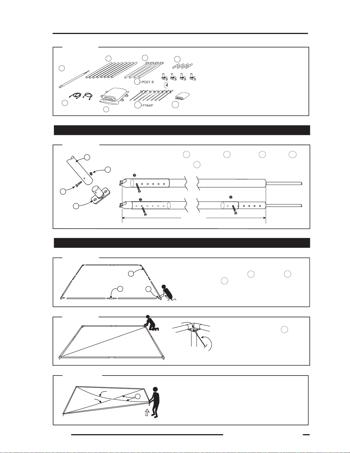
3.) FRAME ASSEMBLY ........................................................................................ 4-5
Post & Centrepole Assembly .................. Step 2....................... PAGE 4
Upper Frame Assembly ......................... Step 3....................... PAGE 4
Cross Cable Installation ......................... Step 4 & 5................ PAGE 4
Cable: Slide Wall Installation (optional) .. Step 6....................... PAGE 5
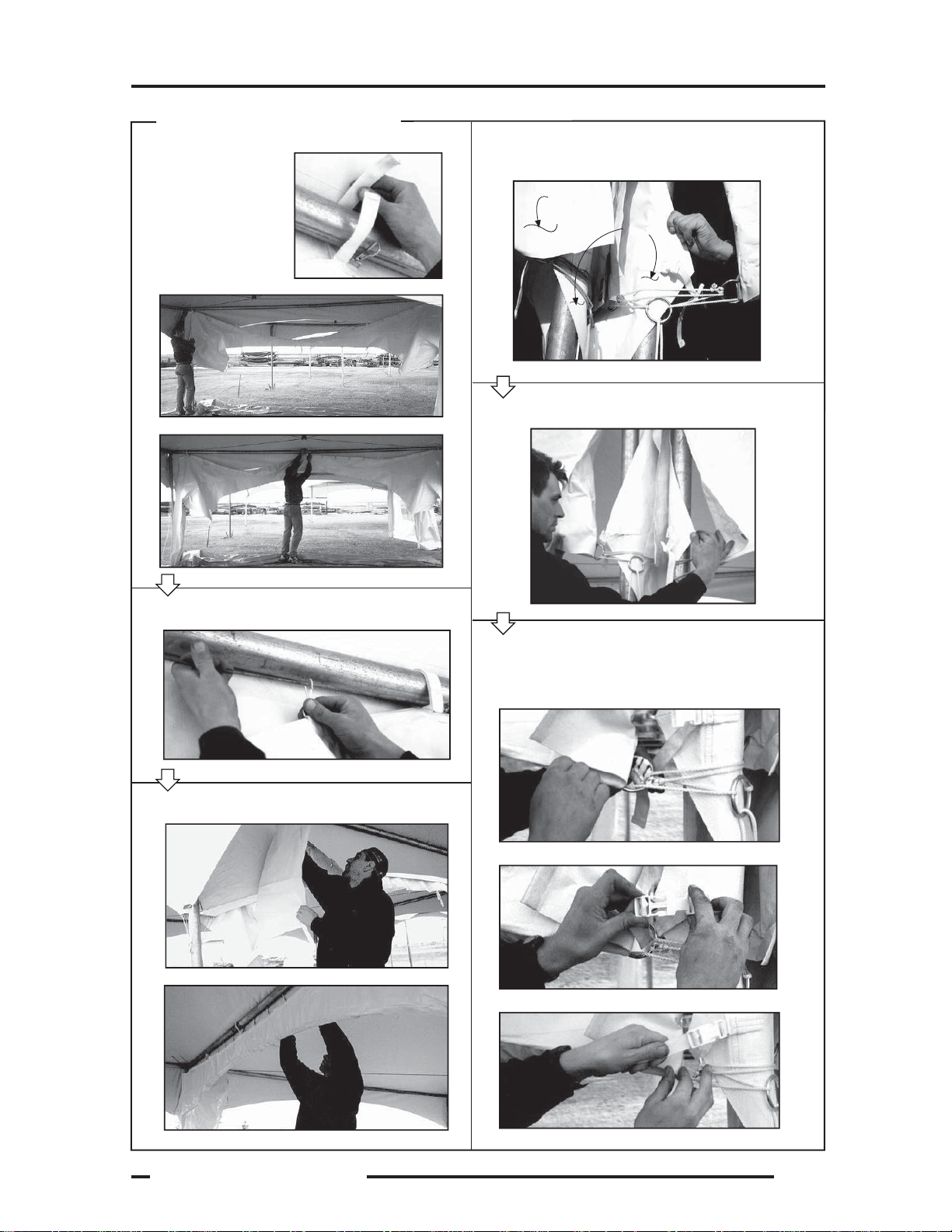
4.) TENT TOP INSTALLATION................................................................................. 5
Protecting Tent Top................................. Step 7....................... PAGE 5
Unfolding Tent Top ................................. Step 8 ...................... PAGE 5
Securing Tent Top to Frame ................... Step 8A/8B .............. PAGE 5
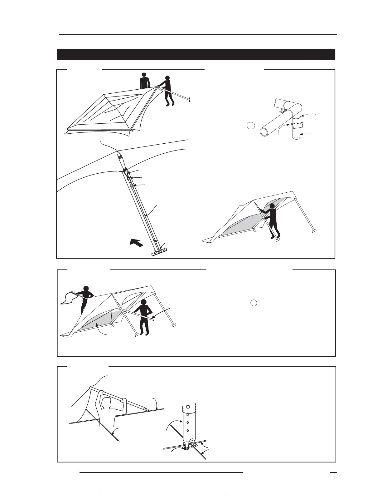
5.) ERECTING THE TENT ................................................................................... 6-7
Installing Posts ....................................... Step 9 ...................... PAGE 6
Installing Centrepole............................... Step 10 - 11.............. PAGE 6
Securing the Structure ........................... Step 12 .................... PAGE 7
6.) GUY ROPE INSTALLATION............................................................................... 7
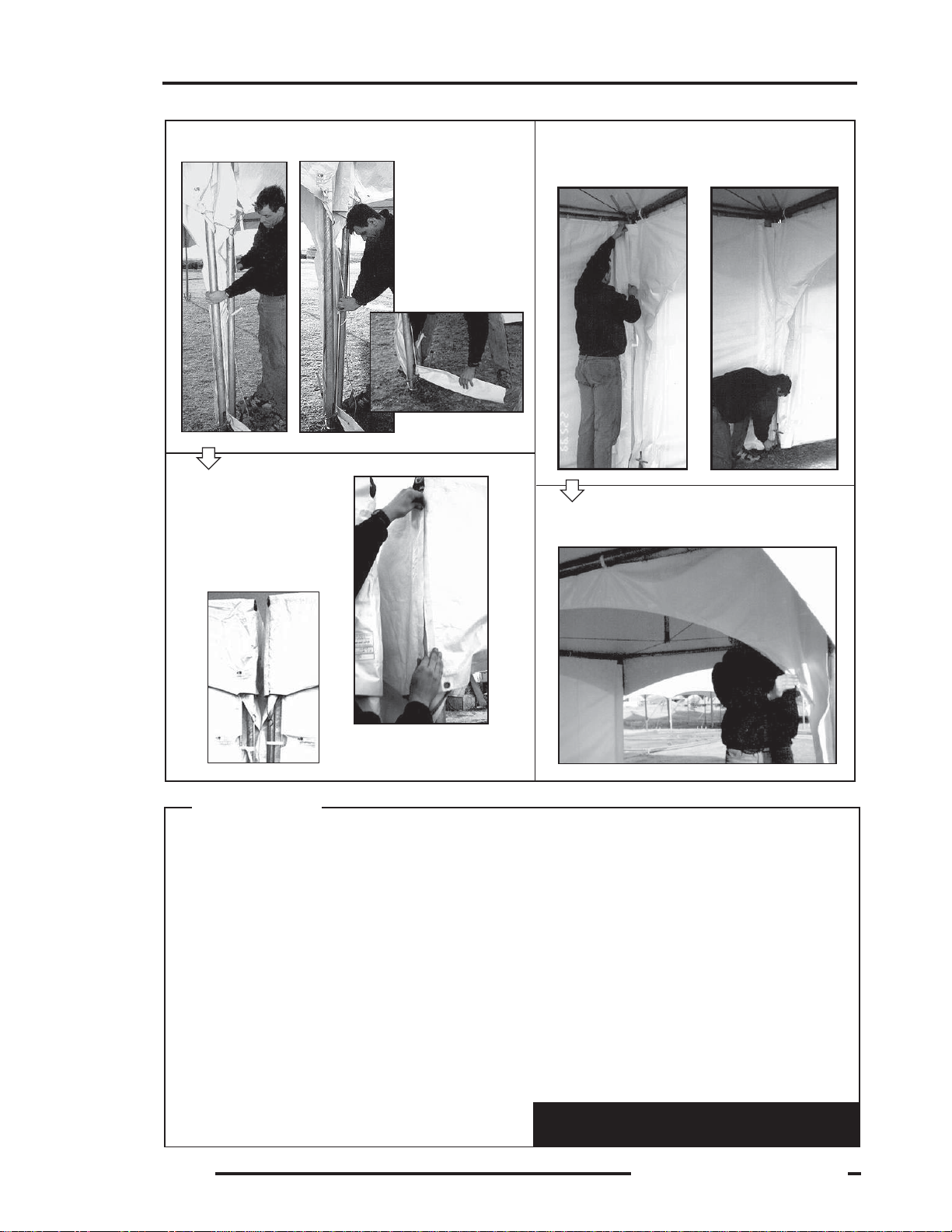
7.) WALL INSTALLATION......................................................................................... 8
8.) JOINER INSTALLATION .................................................................................... 9
9.) SUMMARY........................................................................................................ 10
10.) CARE FOR YOUR VINYL TOPS ..................................................................... 11
11.) MAINTENANCE ............................................................................................... 11
Tent Location
VERY IMPORTANT!
Ascertain tops, guys, and other tent parts are in good operating condition. Any
components showing damage should be replaced immediately.
Before unloading, review the proposed location of the tent. In doing so, take into
account the following:
Hazards Locate, mark, and avoid any overhead or underground electrical, phone, gas,
sprinkler or other lines. Take note and always be aware of any and all hazards. DO
NOT BEGINANY ASSEMBLY UNTIL THE HAZARDS HAVE BEEN MARKED AND
CAN BE SAFELYAVOIDED.
Access Plan the best route for bringing the tent and equipment for the setup onto and off
the site.
Drainage Attempt to influence the location of the tent so that rain or melting snow can drain
away.
Obstacles A clean, level and unobstructed site will provide an easy assembly of the tents.
Weather Do not attempt to setup the tent during thunderstorms, high winds or other extreme
conditions.
Safety Before the set up, instruct the crew on safety procedures. All local safety and fire
regulations must be followed.
ALL SITE PERSONNEL MUST FOLLOW OCCUPATIONAL HEALTH AND SAFETY PROCEDURES.
PAGES
..\graphicshome\marquee\manuals\MQ 20\MQ20H Manual 2009.pdf

Warner Shelter Systems Limited
PAGE 3
BAG
OPTIONAL FLAG POLE
FOR A 3’ X 5’ FLAG
FLAG NOT INCLUDED
11
GUTTER/JOINER WHEN JOINING
TO AN ADJACENT MQ20
additional
stake
MODEL
MQ20H
PEAK MARQUEE TENT
NOMINAL
12
8 6 7
13 1
2
3
12
5
8
8’
5
4
14
16
15
ITEM PART QTY PART# 11033 PART #11037
ALUMINUM STEEL
2 POST 8’ 4 10591 10590
3 BASE; MQ FLAT 4 10514
4 CORNER 90° 4 10628
5 CROSS CABLE 2 7295
6 EVE TUBE 8 10630 7161
7 MIDJOINT 4 10667 7284
8 CENTREPOLE ASSY 1 10978 11544
9 BOLT 5/16-3 NC 4 4093
10 NUT 5/16 NYLOK 4 8369
11 LOCK PIN 5 7843
1 TENT TOP 1 10977
12 STAKE 3/4 - 34” 8 10666
13 FLAG POLE EXT. 1 9523
14
DROP SHEET 1 2100
15 CABLE: SLIDE WALL 20’ as required 10673
16 BASE: MQ ADJ. 24” 4 11064
GUY ROPE as required 10689
FRAME
OPTIONS
11
..\graphicshome\marquee\manuals\MQ 20\MQ20H Manual 2009.pdf
#6857
QUICKLINK
can be ordered
separately
9
2
3
10
10 9
CAUTION: Tension straps must
be maintained tight and even
for proper tensioning
of the canopy
fabric. The fabric
must remain taut
to avoid rain
ponding.
11

Warner Shelter Systems Limited
PAGE 4
Step 1
Step 2
• Check all the parts before assembling
the tent.
• Refer to assembly drawing on page 2
for part quantities and part numbers.
Step 3
• Assemble the Post 8’ 2 with the Base 3 using Bolts 9 and Nuts 10 .
• Assemble the Centrepole 8 using the same type of Bolts and Nuts.
9
2
10
3
• Assemble Corner 90° 4 , Eve Tubes 6 ,
Mid Joints 7 by slipping one part to
another to form the eve frame.
74
6
5CROSS CABLE
6EVE TUBE
Step 5 • Install second Cross Cable.
• To install last loop, lift last corner to shorten the distance
between corners and hook the cable over the pin.
• Lowering the corner causes the corners to adjust their
position and the cables to tighten.
5
Top
Cable
Bottom
Cable
Step 4
• Attach first Cross Cable 5
diagonally from corner to corner.
Hook the cable end loop over the
corner pin.
Corner Pin
Cross
Cables
STEEL
(PART# 11544)
ALUMINUM
(PART# 10978)
CENTRE POLE
ASSEMBLY
3POST BASES 7MIDJOINT
CORNER 90°
16
8CENTREPOLE
* Lock-pins not shown.
PRE ASSEMBLY
FRAME ASSEMBLY
2
2.62 m (8’-7”)
1TENT TOP
This length may vary with Tent Top age and ambient temperature.
Post
Base
2
2
2
16
16
..\graphicshome\marquee\manuals\MQ 20\MQ20H Manual 2009.pdf
DROP
SHEET
19
(NOT INCLUDED)

Warner Shelter Systems Limited
PAGE 5
* Corners are numbered here for ease of explanation only.
• Place the Tent Top midway along one side and
unfold fabric toward the corners.
* Ensure that centre socket pulls out towards the tent
centre, if not rotate entire Tent Top bundle 180°.
• Pull centre socket, towards the centre.
• Attach webbing 1 & 2 to corresponding corners as
shown in STEP 8A below.
• Pull upper layer towards the 3rd corner. Avoid
stepping on Tent Top.
• Repeat to 4th corner.
• Attach webbings 3 & 4 to corresponding corners.
SEE STEP 8B below.
12
Step 8
Step 6 •If Sliding Walls are to be installed, attach the Cable for
Slide Wall 20 to the Corners and tighten turnbuckle.
Step 7
• Unfold Drop Sheet (not included) 19 over
the Cross Cables to protect the Tent Top and
to keep the Tent Top clean.
1
2
Centre Socket
1
2
1
2
43
1
2
3
4
TENT TOP INSTALLATION
PROTECTING THE TENT TOP
Step 8A
• Attach one corner of the Tent Top to the frame
by pulling handle B to place loop webbing A
under the corner loop C .
CB
A• Attach as in 8A, but if tight, insert a
stake through webbing A and press
down and under until the webbing slips
under the corner loop C .
ATTACHING THE LAST
Step 8B
Turnbuckle
Cable: Slide Wall
ATTACHING WEBBING TO CORNER LOOP
Drop Sheet
Cross
Cable
C
A
..\graphicshome\marquee\manuals\MQ 20\MQ20H Manual 2009.pdf
(NOT INCLUDED)
Table of contents
Other Warner Shelter Systems Limited Tent manuals
Popular Tent manuals by other brands

Coleman
Coleman 2000033134 Assembly & instruction manual

Ozark Trail
Ozark Trail W784.1 Assembly instructions and owner's manual

SlingFin
SlingFin CrossBow 2 instructions

Coleman
Coleman 9600-141 instructions

Palram
Palram Arizona 5000 Wave - WINGS manual

COVERPRO
COVERPRO 56184 Owner's manual & safety instructions