Page 9
X series Operations Manual Oct 27, 2023
2.6. Laser Firing Delay
There is a regulatory requirement that the “laser firing” LED should illuminate for a short period of time
before the laser actually begins emitting hazardous radiation. This is so that the operator and bystanders
have an opportunity to visually observe the LED illumination and take appropriate defensive action if
this circumstance was unexpected (e.g., close their eyes, look away, disable the laser through software,
hit an “emergency stop” wall-box linked to the remote interlock, turn the key-switch, etc).
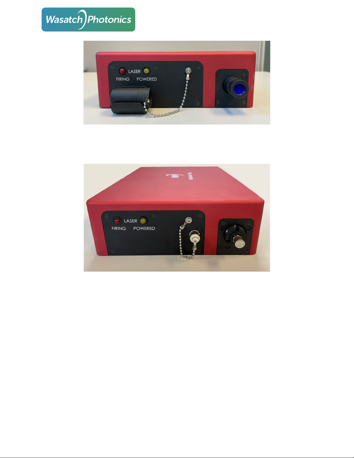
2.7. Laser Interlock Key-Switch
Wasatch Photonics Raman spectrometers with integrated lasers include a laser interlock key-switch on
the back face of the spectrometer (opposite the collection / excitation optics). This key is removable,
and must be turned to a “firing” position before the laser can be armed and fired.
If the key is not inserted and turned to the “firing” position, neither the yellow “Armed” nor the red
“Firing” LED can illuminate, nor can the laser fire.
If the key is inserted and turned to the “firing” position, the yellow “Armed” LED may illuminate, but the
red “Firing” LED should not illuminate until the laser is instructed to fire through software.
If the key is turned “off” or removed while the laser is firing, the laser will immediately cease firing. Re-
inserting and turning the key back to the “firing” position will not automatically cause the laser to
resume firing: a fresh software command must be sent to re-instruct the laser to resume firing.
2.8. Remote Laser Interlock
Wasatch Photonics Raman spectrometers with integrated lasers include a remote laser interlock jack on
the back face of the spectrometer (adjacent to the key-switch). This jack uses a standard stereo audio
plug connector (SP-3540A, DigiKey 102-4779-ND), simplifying development of compatible plugs for your
laboratory or OEM requirements.
If the jack is left empty (no plug inserted), the laser interlock circuit will be broken (“open”) and the laser
will not fire. This will likewise prevent the yellow “Laser Armed” LED from illuminating.
The microphone plug should be wired to your laboratory’s remote door-entry / remote interlock system.
Such interlock circuits are varied, and can include one or multiple nodes such as the following:
●Door interlocks which open (disarm) when the magnetic seal is broken, and close (arm) when
the magnets connect, such that arrival of an unexpected visitor causes the laser to immediately
disable.
●“Emergency Stop” buttons which allow users to quickly deactivate the laser by depressing or
signaling a conveniently large and accessible physical switch.
●“Exit Override” buttons which temporarily disable “downstream” interlocks by forcibly closing
the circuit (typically only for a few seconds and accompanied by an audible siren).
●“Entry Override” keypads allowing the door override to be temporarily disabled with a
passcode.
●Interlocked power strips, such that opening of the interlock circuit cuts power to connected
devices.