Wascomat H7-55 User manual

Installation manual
Washer extractor
H7–55
Type W.55.H
Original instructions
438905433/EN
2019.05.21


Contents
Contents
1 Safety Precautions ..............................................................................................................................5
1.1 General safety information..........................................................................................................6
1.2 Commercial use only..................................................................................................................6
1.3 Symbols....................................................................................................................................6
2 Technical data.....................................................................................................................................7
2.1 Drawing ....................................................................................................................................7
2.2 Technical data ...........................................................................................................................8
2.3 Connections ..............................................................................................................................8
3 Setup .................................................................................................................................................9
3.1 Unpacking.................................................................................................................................9
3.2 Siting ......................................................................................................................................10
3.3 Mechanical installation .............................................................................................................10
4 Water connection .............................................................................................................................. 11
5 Connection of external dosing systems ............................................................................................... 11
5.1 Connection of the hoses ........................................................................................................... 11
5.2 Electrical connection of external dosing system..........................................................................12
5.2.1 Machine with connectors.................................................................................................13
5.2.2 Machine without connectors............................................................................................14
5.2.3 Outputs .........................................................................................................................15
5.2.4 Inputs ............................................................................................................................16
6 Drain connection ...............................................................................................................................17
7 Electrical connection..........................................................................................................................18
7.1 Electrical installation ................................................................................................................18
7.2 Electrical connections ..............................................................................................................18
7.3 Machine connection .................................................................................................................19
7.4 Functions for I/O-cards.............................................................................................................21
7.4.1 External coin meter/Central payment (2A) ........................................................................21
7.4.2 Central payment (2B)......................................................................................................22
7.4.3 Central payment (2C) .....................................................................................................23
7.4.4 Outputs for detergent signals and inputs for pause signals, "empty" signal and price re-
duction (2D) ...................................................................................................................24
7.4.5 Central booking/payment (2F) .........................................................................................25
8 At first power up ................................................................................................................................26
8.1 Select language.......................................................................................................................26
8.2 Set time and date.....................................................................................................................26
9 Function check..................................................................................................................................27
10 Disposal information..........................................................................................................................27
10.1 Disposal of appliance at end of life ............................................................................................27
10.2 Disposal of packing..................................................................................................................28
The manufacturer reserves the right to make changes to design and component specifications.


Installation manual 5
1 Safety Precautions
• Only use detergent intended for water-wash of textiles. Never use dry
cleaning agents.
• The machine shall be connected with new water hoses. Re-used
water hoses must not be used.
• The machine's door lock must under no circumstances be bypassed.
• If the machine develops a fault, this must be reported to the person in
charge as soon as possible. This is important both for your safety and
that of others.
• DO NOT MODIFY THIS APPLIANCE.
• Servicing shall be carried out only by authorized personnel.
• Only authorized spare parts, accessories and consumables shall be
used.
• When performing service or replacing parts, the power must be
disconnected.
• When the power is disconnected, the operator must see that the ma-
chine is disconnected (that the plug is removed and remains removed)
from any point to which he has access. If this is not possible, due to
the construction or installation of the machine, a disconnection with a
locking system in the isolated position shall be provided.
• In accordance with the wiring rules: mount a multi-pole switch prior to
the machine to facilitate installation and service operations.
• The openings in the base, shall not be obstructed by a carpet.
• Maximum mass of dry cloth: 6 kg.
• A-weighted emission sound pressure level at working stations:
– Wash: <70 dB(A).
– Extraction: <70 dB(A).
• Additional requirements for the following countries; AT, BE, BG, HR,
CY, CZ, DK, EE, FI, FR, DE, GR, HU, IS, IE, IT, LV, LT, LU, MT, NL,
NO, PL, PT, RO, SK, SI, ES, SE, CH, TR, UK:
– The appliance can be used in public areas.
– This appliance can be used by children aged from 8 years and
above and persons with reduced physical, sensory or mental capa-
bilities or lack of experience and knowledge if they have been given

6Installation manual
supervision or instruction concerning use of the appliance in a safe
way and understand the hazards involved. Children shall not play
with the appliance. Cleaning and user maintenance shall not be
made by children without supervision.
• Additional requirements for other countries:
– This appliance is not intended for use by persons (including chil-
dren) with reduced physical, sensory or mental capabilities, or lack
of experience and knowledge, unless they have been given super-
vision or instruction concerning use of the appliance by a person
responsible for their safety. Children should be supervised to en-
sure that they do not play with the appliance.
1.1 General safety information
The machine is only intended for water-wash use.
Do not hose down the machine with water.
In order to prevent damage to the electronics (and other parts) that may occur as the result of condensation, the ma-
chine should be placed in room temperature for 24 hours before being used for the first time.
1.2 Commercial use only
The machine/machines covered by this manual is/are made for commercial and industrial use only.
1.3 Symbols
Caution
Caution, high voltage
Read the instructions before using the machine
Installation manual 7
2 Technical data
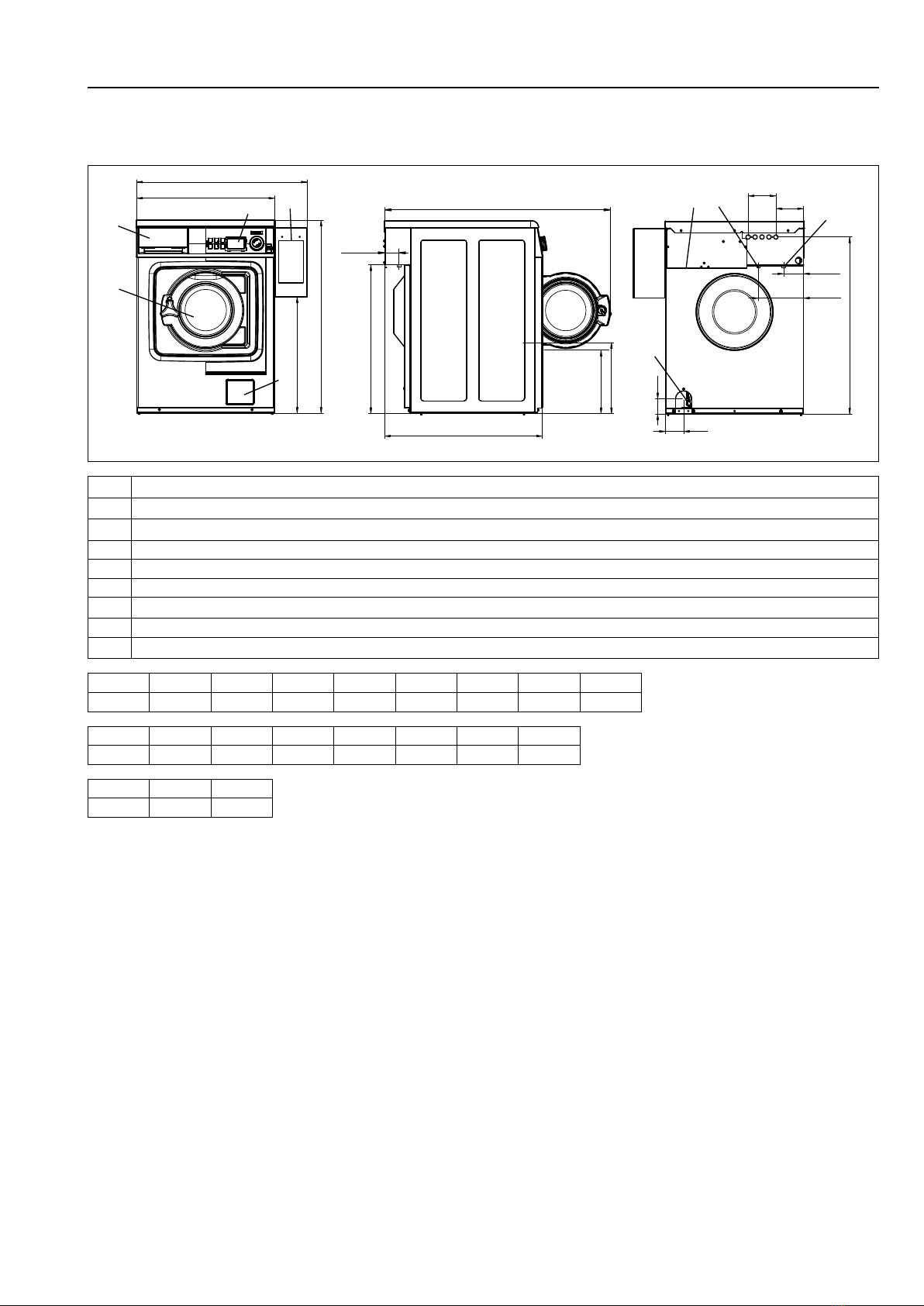
2.1 Drawing
6
7
A1
A2
2
3
19
C
M
N
H
E
B
K
L8
4
5
F
G
I
J
O
D2
D1
fig.8025
1 Operating panel
2 Detergent container
3 Door opening, ⌀255 mm
4 Cold water
5 Hot water
6 Drain valve
7 Drain pump
8 Electrical connection
9 Payment system
A1 A2 B C D1 D2 E F
mm 595 735 681 832* 284 310 641 84
G H I J K L M
mm 194 48 65 78 120 119 501
N O
mm 974 764
* Adjustable height: 25 mm.
8Installation manual
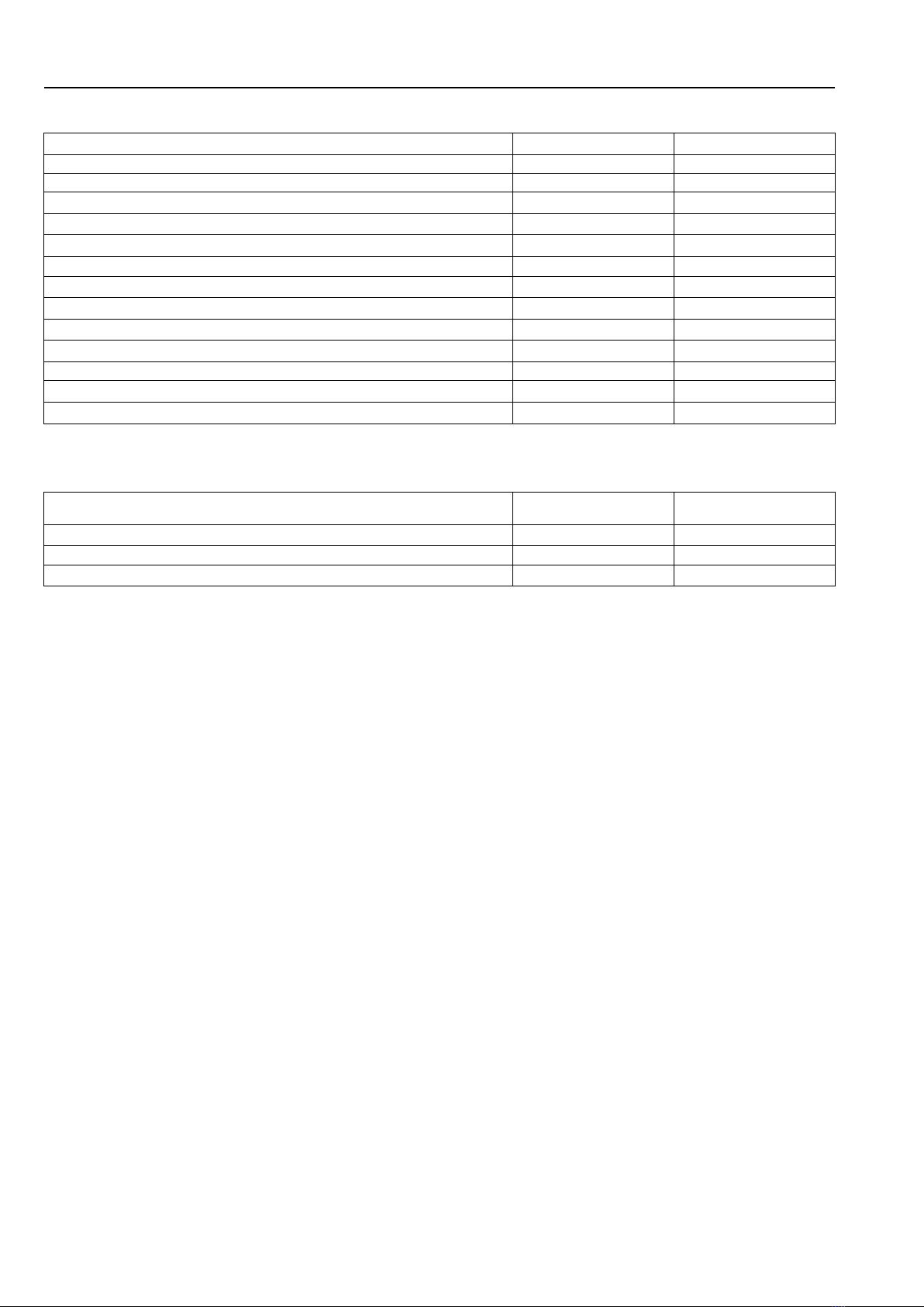
2.2 Technical data
Weight, net kg 100
Drum volume litres 53
Drum diameter mm 452
Drum speed during wash rpm 35/54
Drum speed during extraction rpm 1450
Drum speed during extraction, Marine model rpm 1300
G-factor, max. 530
G-factor, max. Marine model 425
Heating: Electricity kW 4.4
Heating: Hot water x
Frequency of the dynamic force Hz 24.2
Floor load at max extraction kN 1.2±0.3
Sound power/pressure level at extraction* dB(A) 70/56
Sound power/pressure level at wash* dB(A) 56/42
* Sound power levels measured according to ISO 60704.
2.3 Connections
Water valves DN
BSP
20
3/4”
Capacity at 300 kPa l/min 17
Drain valve ⌀outer mm 50
Draining capacity (pump) l/min 160
Installation manual 9
3 Setup
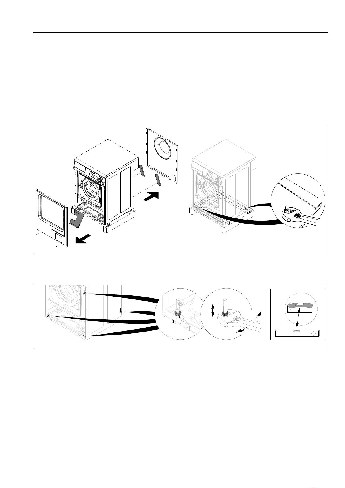
3.1 Unpacking
The machine is delivered bolted onto the transport pallet and packed in a crate or box.
Remove packing from the machine.
Remove the front panel by undoing the two screws on the bottom edge.
Remove the rear panel by undoing the screws.
Remove the three transport supports, one at the front and two at the back. Save the transport supports if the machine
needs to be moved in the future.
Remove the bolts between the machine and pallet. There is one to the right in the front of the machine and another
diagonally opposed to it, at the back of the machine.
fig.W00980
Remove the machine from the pallet. The machine shall be lifted in the bottom frame.
Mount the enclosed supporting feet and level the machine.
fig.W00981
Remount the front- and the back panel.
Place the machine on its final position.

10 Installation manual
3.2 Siting
Install the machine close to a floor drain or open drain.
The machine should be positioned so that there is plenty of room for working, both for the user and service personnel.
The figure shows minimum distance to a wall and/or other machines.
500 mm /
20 inch
70 mm /
2 3/4 inch
70 mm /
2 3/4 inch
fig.W00176B
3.3 Mechanical installation
If the machine is not to be mounted on a base the machine must be fastened to the floor.
Mark and drill two holes (⌀8 mm) about 40 mm deep.
C A
D
G
FE
B
H
FRONT = drilling points
= position of feet
fig.5358
A B C D E F G H
mm 530 490 35 125 290 150 40 50
Installation manual 11
Place the machine over the two drilled holes. The holes are at the front of the machine.
Level the machine with the feet of the machine. Screw in the feet as much as possible before starting to level the ma-
chine. This will make the machine stand steadier.
Insert the expansion bolts supplied into the holes drilled in the floor. Fit the washers and nuts and tighten well.
It is of the upmost importance that the machine is placed in level, from side to side as well as front to rear. If the
machine is not properly levelled, it may result in out-of-balance without a real out of balance in the drum.
4 Water connection
All water intake connections to the machine should be fitted with manual shut-off valves and filters, to facilitate instal-
lation and servicing.
Water pipes and hoses should be flushed clean before installation.
The machine shall be connected with new water hoses. Re-used water hoses must not be used.
Hoses are to be of an approved type and grade and comply with IEC 61770.
After installation hoses must hang in gentle arcs.
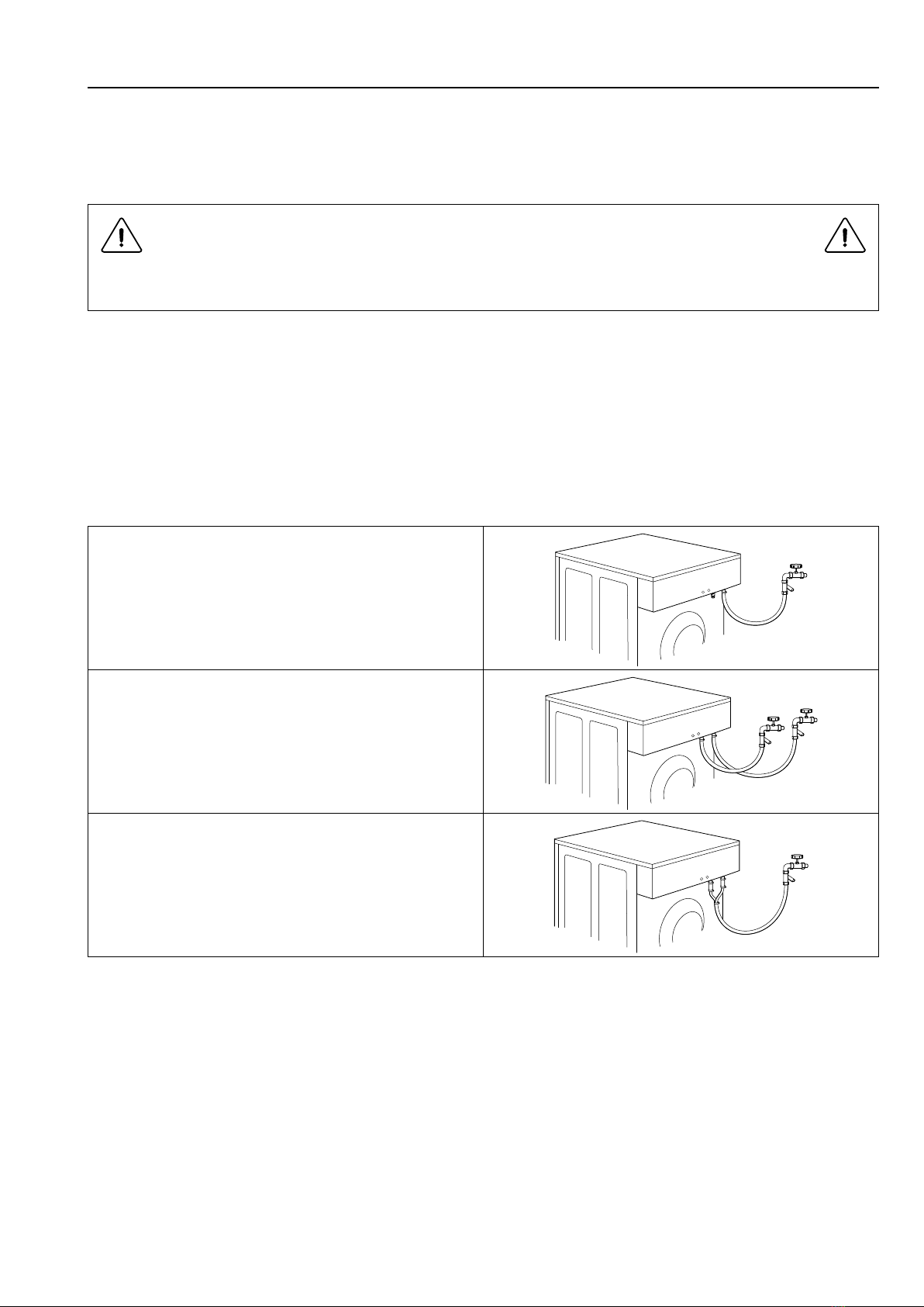
The machine can have one or two supply hoses.
Machine with cold water intake only.
Machine with hot and cold water intake.
When the machine is prepared for cold and hot water but no hot water
is available, both valves must be connected with cold water.
Water pressure:
Miniumum: 50 kPa (0.5 kp/cm2)
Maximum: 1 MPa (10 kp/cm2)
Recommended: 200-500 kPa (2–5 kp/cm2)
For WRAS-approved machines; always check connection requirements on WRAS website.
5 Connection of external dosing systems
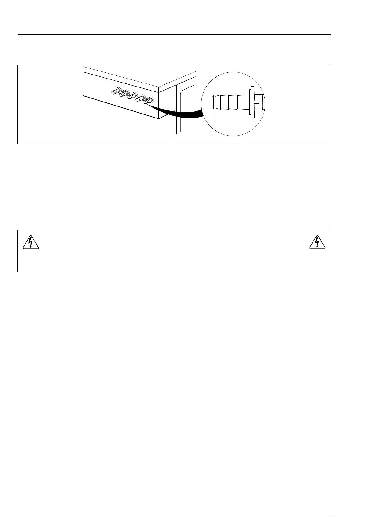
5.1 Connection of the hoses
The machine is prepared for connection of external dosing systems or water re-use systems etc.
12 Installation manual
Cut the top of the hose nipples to be used as showed in the figure.
Connect the hoses to the hose nipples.
fig.5964A
Always connect hoses on connections with a hose clamp.
If the hoses are made of a soft material such as silikon or similair, use a cable tie to fasten the hose on the connec-
tion. If the hoses are made of a hard material, it is not recommended to make the connection tighter by using a cable
tie.
Note!
Equipment for external dosing must only be connected to work on pump pressure and not on network
pressure.
5.2 Electrical connection of external dosing system
The power supply to the external dosing system must never be connected to the machine’s incoming terminal
block or to the edge connectors on the I/O-board.
Installation manual 13
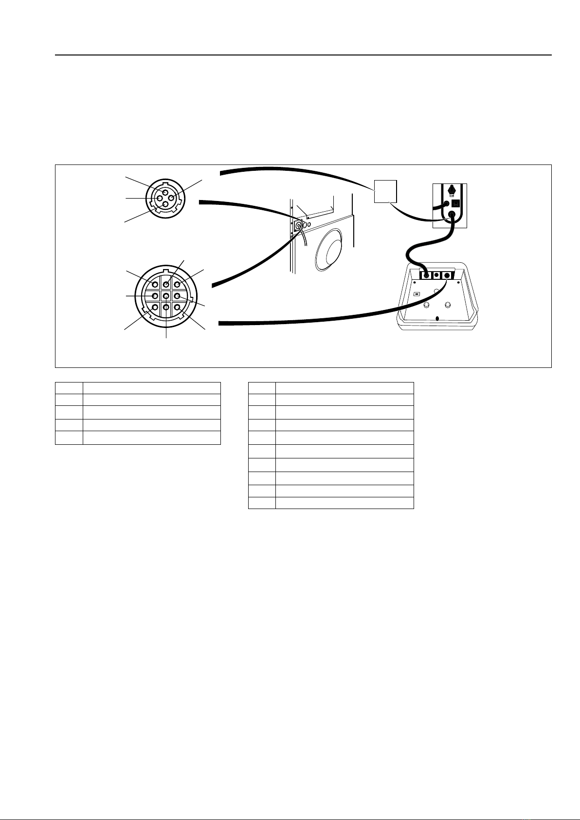
5.2.1 Machine with connectors
Connect the external dosing system to connections A and B on the machine.
Connect the signal cable to B and the power supply to A.
For Efficient dosing system the cables are delivered with the machine.
Connect the power supply cable to the machine A and the other end of the cable together with the cable from Effi-
cient Dosing in a connection box or with plug and receptacle.
Connect one end of the cable to the Efficient Dosing Controller J2 and the other end to the machine B.
Connection box
B
12
3
4
1
2
3
4
5
7
6
9
J1 RJ11 J2
Controller
Pump unit
A
fig.6598B
A B
1 Line 1 Neutral
2 Neutral 2 Program run
3 3 Gnd
4 Ground 4 Signal 2
5Signal 3
6 Signal 4
7Signal 5
8 Rx
9 Tx

14 Installation manual
5.2.2 Machine without connectors
Connect the external dosing system to the I/O board, which is located to the right of the incoming power supply.
The I/O board has edge connectors for connecting external dosing systems.
Edge connectors on the I/O board can be loosened for connecting cables.
1357911
13
15
17
19
246810
12
14
16
18
fig.6238

Installation manual 15
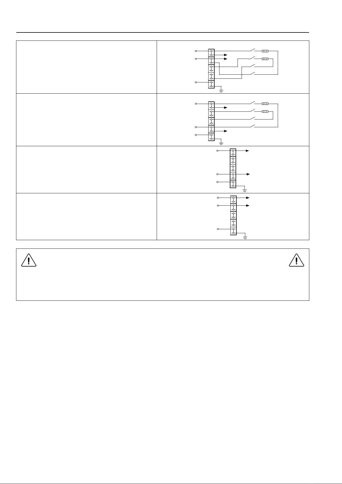
5.2.3 Outputs
Connect the power supply (e.g. 24V DC) for the external liquid supplies to 9 and 10. If an internal power supply (from
the machine) is being used, it can be taken from 1 (N) and connected to 9 and from 2 (L) and connected to 10. Max
load on the outputs 0.5 A.
Signals for external liquid supplies 1-5 are connected to 12-16 where connector:
12 = Signal 1
13 = Signal 2
14 = Signal 3
15 = Signal 4
16 = Signal 5
fig.6236B
6M14 6F01 6R01 6F02 Other programs
Signal 1 -Pre-wash Pre-wash Pre-wash Pre-wash
Signal 2 Main wash Main wash Main wash Main wash Main wash
Signal 3 Softener Softener Softener Softener Softener
Signal 4 Mop last rinse Desinfection Pr 1 last rinse Mainwash -
Signal 5 Bleach Bleach Bleach Bleach Bleach
16 Installation manual
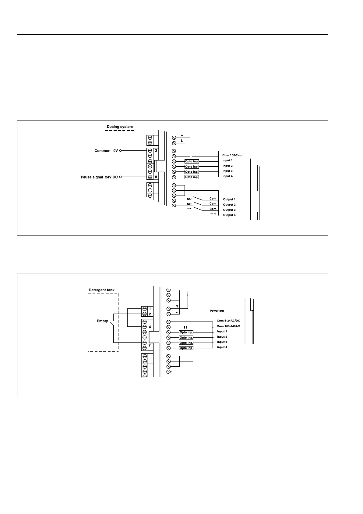
5.2.4 Inputs
The signal level can be 5-24V DC/AC or 100- 240V AC. For 5-24V, the signal reference is connected to 3 and for
100-240V to 4. Potentials on the inputs cannot be mixed.
Note!
The I/O board will be damaged if the voltage on connection 3 is too high > 24V.
Connection 8 may be connected if the program is to pause, e.g. while detergent is being dosed.
The figure shows an example of engaging a 24V pause signal. The program will pause for as long as the pause sig-
nal remains activated (high).
fig.6266
Connection 7. If this is connected, an error message will be displayed if any of the chemical tanks are empty. The pro-
gram will continue, however.
The figure shows an example of engaging a normal open contact.
fig.6265

Installation manual 17
6 Drain connection
Drain valve
The drainage pipe should be located over a floor drain, drainage channel or the like so that the distance between the
outlet and the drain is at least 25 mm.
fig.2036
Drain pump
The drainage pipe should be located over a floor drain, drainage channel or the like.
The highest part of the drain hose shall be positioned according to the figure.
Make sure there is no kinks in the hose.
650 mm ± 50 mm /
25 9/16 inch ±
1 15/16 inch
max
100 mm
fig.2029A
18 Installation manual
7 Electrical connection
7.1 Electrical installation
The electrical installation may only be carried out by qualified personnel.
In accordance with the wiring rules: mount a multi-pole switch prior to the machine to facilitate installation and service
operations.
Connect the machine’s cable to the switch.
Check that the earth has been connected in the correct way.
For the rating of the supply cable, check the local regulations. Min. outer diameter for supply cable ø 10 mm.
The connecting cable shall hang in a gentle curve.
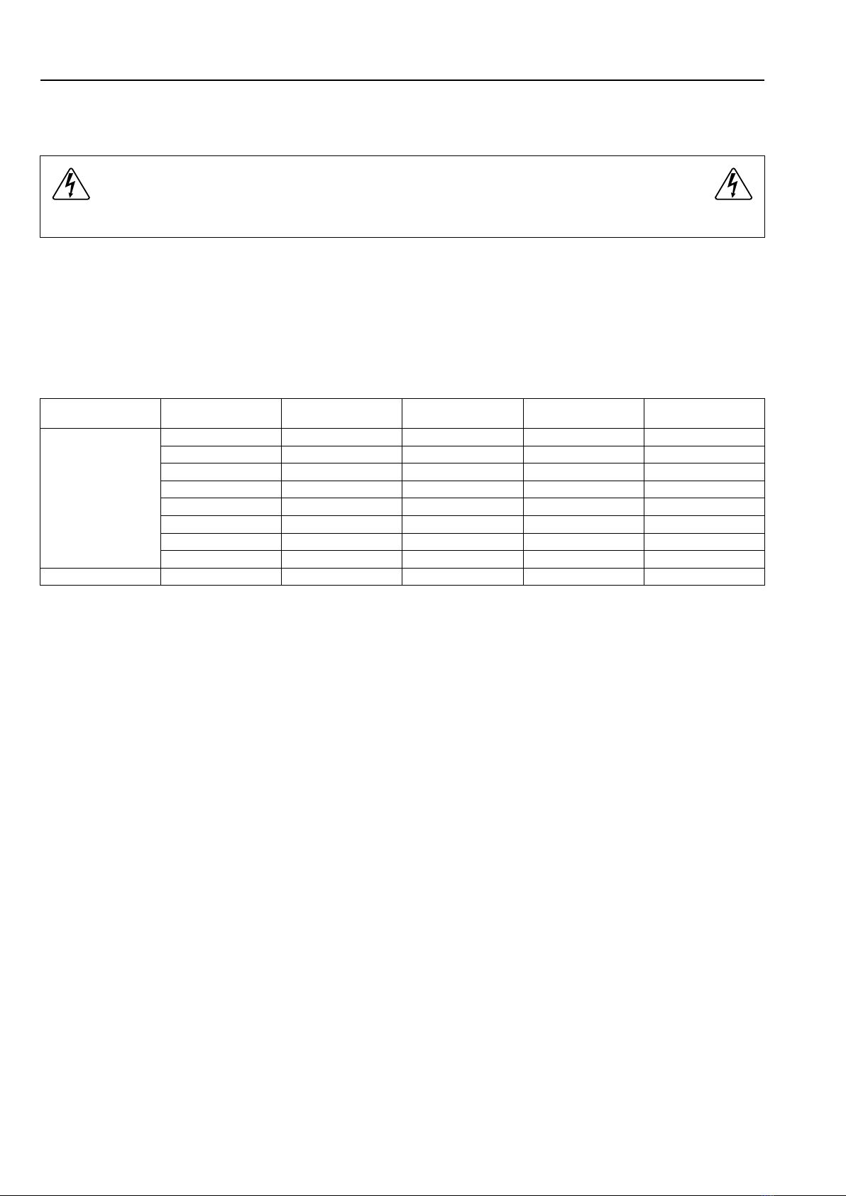
7.2 Electrical connections
Heating alternative Main voltage Hz Heating power
kW
Total power
kW
Recommended fuse
A
Electric heated 220–240V 1N ~ 50/60 2.2/2.8 2.4/3.0 16
220–240V 1N ~ 50/60 4.4 4.6 20
220-230V 1N ~ 50/60 4.4 4.6 25
220–240V 3 ~ 50/60 4.4 4.6 16
220–230V 3 ~ 50/60 4.4 4.6 20
380–415V 3N ~ 50/60 4.4 4.6 10
380-415V 3 ~ 50/60 3.6 3.8 10
440V/480 3 ~ 50/60 4.0/4.4 4.3/4.7 10
Non heated 110–480V 1/3 ~ 50/60 -0.5 10

Installation manual 19
7.3 Machine connection
The machine can be switched/reconnected to the following options.
Connection option 380–415V/3N~ 4.4 kW
Electric heated
301
302
303B
303A
L1
L2
L3
N
PE
87
K21
65
43
21
E2
E1
L
N/L
Connection option 380–415V/3~ 4.4 kW
Electric heated
301
302
303B
303A
L1
L2
L3
PE
87
K21
65
43
21
E2
E1
L
N/L
Connection option 208–240V/3~ 4.4 kW
Electric heated
301
302
303B
303A
L1
L2
L3
PE
87
K21
65
43
21
E2
E1
L
N/L
Connection option 208–240V/1~ 4.4 kW
Electric heated
301
302
303B
303A
L1
L2
PE
87
K21
65
43
21
E2
E1
L
N/L
Connection option 208–240V/1N~ 4.4 kW
Electric heated
301
302
303B
303A
L1
N
PE
87
K21
65
43
21
E2
E1
L
N/L
Connection option 208–240V/1~ 2.2 kW
Electric heated
302
303B
303A
301
L1
L2
PE
87
K21
65
43
21
E2
L
N/L
Connection option 208–240V/1N~ 2.2 kW
Electric heated
302
303B
303A
301
L1
N
PE
87
K21
65
43
21
E2
L
N/L
20 Installation manual
Connection option 208–240V/1~ 2.2 kW
Electric heated
302
303B
303A
301
L1
L2
PE
E1
E2
87
K21
65
43
21
L
N/L
Connection option 208–240V/1N~ 2.2 kW
Electric heated
302
303B
303A
301
L1
N
PE
E1
E2
87
K21
65
43
21
L
N/L
Connection option 100–240V/1N~
Non heated
L1
PE
N
L
N/L
Connection option 100–240V/1~
Non heated
L1
PE
L2
L
N/L
Reconnection/switchover of this type can not be performed on machines fitted with a transformer.
The machine can not be switched from 50 Hz to 60 Hz or vice versa.
In cases where the machine data plate does not state the new voltage option, this should be added to the ma-
chine data plate.
Other manuals for H7-55
1
Table of contents
Other Wascomat Scrubber manuals

Popular Scrubber manuals by other brands

Diamond Products
Diamond Products CROWN G20 Operator's manual

Abicor Binzel
Abicor Binzel xFUME VAC FLEX operating instructions

BETCO
BETCO GENIE CE HD APS Operator and parts manual

Nilfisk-Advance
Nilfisk-Advance Advance SC8000 48 LPG Instructions for use

Nederman
Nederman Single Exhaust Extractor instruction manual

Tennant
Tennant T290 Operator's manual


