Water Hero P-100 User manual

P-100
INSTALLATION AND OPERATION
MANUAL


Thank you for purchasing the Water Hero P-100, which oers
whole-building leak detection and water conservation monitoring.
Water Hero P-100
Main Controller
Water Meter, Sensor
Cap & Unions
Motorized Ball Valve
[~6 foot cord length]
5V Power Supply
[~6 foot cord length]
Sensor Cable
[~6 foot length]
This box contains:
2

Water Hero P-100 is plumbed into a water
supply line. Improper installation can cause
leaks. Ensure installation is completed
by a licensed plumber and abides by the
following guidelines:
• In accordance with state/local building
codes
• Wear personal protective equipment
when installing the Water Hero P-100
• Do not open the Water Hero Main
Controller or Sensor Cap. If you have
trouble , contact Water Hero support
• Use the Water Hero only where it
complies with applicable rules and
regulations
• Install the Water Hero P-100 System
indoors where it will not be exposed to
direct sunlight, water or extremely low
or high temperatures. No exposure to
water. RH < 90%; Temp 0 to 140 F
• Accuracy of the Water Hero P-100 is
dependent on flow rate – accuracy is
typically within 10%
All Water Hero terms and conditions,
privacy policies and warranty
policies can be found on the Water
Hero website
www.waterheroinc.com/legal
For installation and technical support
questions, reach out to us at:
support@waterheroinc.com
Warning Terms & Conditions
Contact Us
3

Start- Up Guide P-100

Set up your Water Hero
Main Controller
Valve Power Cord
Blue Sensor Cable
Power Adapter
1. Place Water Hero near location it will be plumbed
2. Screw round white Sensor Cap to top of brass meter
3. Connect blue Sensor Cable to jacks on round white Sensor Cap and
Main Controller
4. Connect Valve Power Cord to Main Controller
5. Water Hero Main Controller will power up; a blinking green LED and
solid yellow LED will illuminate
5

Connect to Your WiFi Network
Option #1: Using an iPad or iPhone
1. Search the Apple App Store for “Water Hero Remote” and download
2. Open the app and tap the text that reads “New Customer? Tap here to
create an account”
3. Enter your e-mail address & password; tap the green tab
Note: This e-mail is where you’ll receive leak e-mail alerts
6

Connect to Your WiFi Network
Option #1: Using an iPad or iPhone
4. You’ll be directed to the “My Devices” page; on the bottom right tap
“+”
5. Follow Step 1 instructions, and tap “Next” at the bottom of the page,
then continue through Step 4
7

Connect to your WiFi Network
Option #2: Using any smartphone or computer
1. Using your device (i.e.
computer, laptop, or mobile
device), open a web browser.
Enter URL mywaterhero.net
and select “Create an account”
2. Enter your e-mail address and
desired password. Remember
your account e-mail and
password
3. Select “Create Account” and
wait for the page to load for
approximately 30 seconds
4. Close browser
8

1. Turn the Main Controller to its side; ensure the yellow light* is lit
solid and the green light is blinking
Access the Device Configuration Page
2. Go to WiFi settings
on your smartphone or
computer; select “Water
Hero Access Point” as
your WiFi network
*If Yellow light is not illuminated perform Network Reset, P. 23 of manual
9

3. Once connected to “Water Hero Access Point” WiFi network,
open an Internet browser (we recommend Chrome) and go to URL
http://192.168.1.1 to access Water Hero’s “Device Configuration Page”
Access the Device Configuration Page
hp://192.168.1.1
10
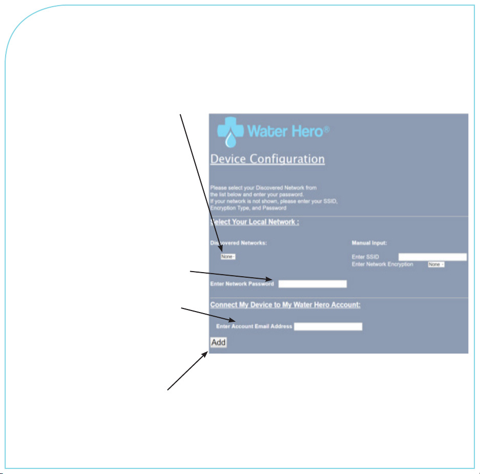
1. Click the drop down
menu under “Discovered
Networks”. If available,
select the (SSID) Wi-Fi
Network that you’d like
Water Hero to connect with.
Signal strength is indicated
and should be between
-60 and -20 for optimal
connection strength.
2. Enter your Wi-Fi network
password (Case Sensitive)
3. Enter the e-mail address
associated with your Water
Hero Account
4. Once all information is
entered, press “Add”
Enter Wi-Fi Network Information
Do NOT enter data in ”Manual Input” Section
unless prompted by Water Hero sta
11

1. Upon successful connection, red light will blink, yellow light will blink
and then green light will remain blinking*
2. Open a browser and enter URL www.mywaterhero.net
3. Enter e-mail address associated with your Water Hero Account
password and press login to view your device online
*If green light not blinking, conduct Network Reset on P. 23 of manual
Verify Water Hero Connection
12

1. The valve and meter of the Water Hero P-100 can be installed in a
horizontal or vertical orientation
2. Motorized Ball Valve should be installed upstream from the meter
3. Water Hero P-100 MUST be installed downstream of fire suppression
systems and is recommended for installation downstream of irrigation
and water soener systems
4. Water Hero should be installed indoors, protected from the elements,
freezing temperatures or excessive humidity
5. Unit’s Main Controller is powered by a 5V power supply and should be
located with access to a 2.4 GHz Wi-Fi connection*
6. Unscrew Sensor Cap and disconnect Motorized Ball Valve from Main
Controller before plumbing in Water Hero
7. Plumb Water Hero Meter & Motorized Ball Valve into pipe - reconnect
cords and assembly when complete; verify connection ***blinking
green light= *Press Reboot (Button 1, P. 19) if green light is not blinking
aer reconnection
Prepare for installation of Water Hero
*Wi-Fi networks can not be behind a corporate firewall or sign-in page
13

Prepare for installation of Water Hero
Water Hero P-100 MUST be
plumbed aer (downstream of) fire
suppression systems
Main Controller
Motorized Ball
Valve
Power
Adapter P-100 Water
Meter
Main Water
Supply
STREET SIDE INSIDE BUILDING
14

Features & Functionality
P-100

1. Login to your account at mywaterhero.net and you will be presented
the “My Devices” tab. This tab shows all Water Hero devices registered
to the account. It also shows total water flow amount for each device
listed and the ambient temperature at the meter sensor.
2. Click on the Device Name to access a dashboard that shows
real-time information
My Devices
New Customer
new@customer.com
Your Device online 36349.3 gallons 48 F
16

Dashboard
Gauge
displays
real time
Leak
detection
mode
selector*
Ambient air
temperature
Operation
Selector
Hourly
water
usage
data
*Home/away mode alerts and shut-os can be adjusted under the Settings Tab
Remote
Valve
17

Utilities
“Measure Flow” is a stopwatch
feature that allows user to view
the amount of water that has
been used over a period when
the feature is engaged. Pressing
“Start” or “Stop” controls when
water is being recorded
“Timed Measurement” allows
user to find out how much
water was used during a
specific period of time. Set the
target date and times to get
consumption by clicking on the
“start” and “end” panes and
toggling. Each calculation takes
about 10 seconds.
18

Home and Away Mode
panels allow user to set
limits aer which alerts
and automatic shut-o
are triggered
Temperature alerts panel
allow user to set low
and high temperature
warnings. Temperature
extremes could indicate
frozen pipes or a fire
Notifications panel
allows user to select
method by which
warnings and alerts
are sent
Settings
19
Other manuals for P-100
1
Table of contents
Popular Security Sensor manuals by other brands

Aling Conel
Aling Conel 72203 installation manual

elobau
elobau 153 Series Translation of the original operating instructions

B.E.G.
B.E.G. LUXOMAT PD4-M-DALI/DSI-C Installation and operating instruction

Alula
Alula RE106 install guide

NAPCO
NAPCO GEMC-WL-CO installation instructions

NMT
NMT V-Detector user manual


