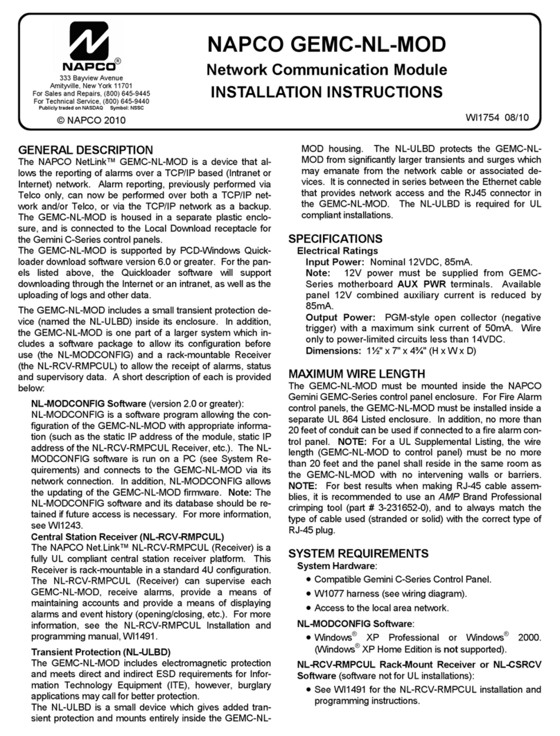
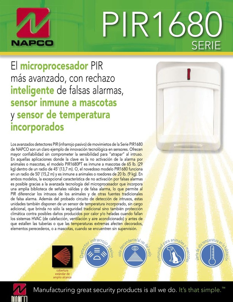
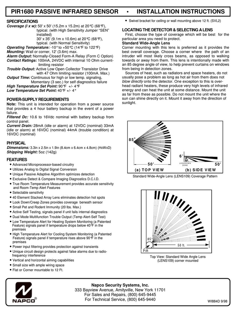
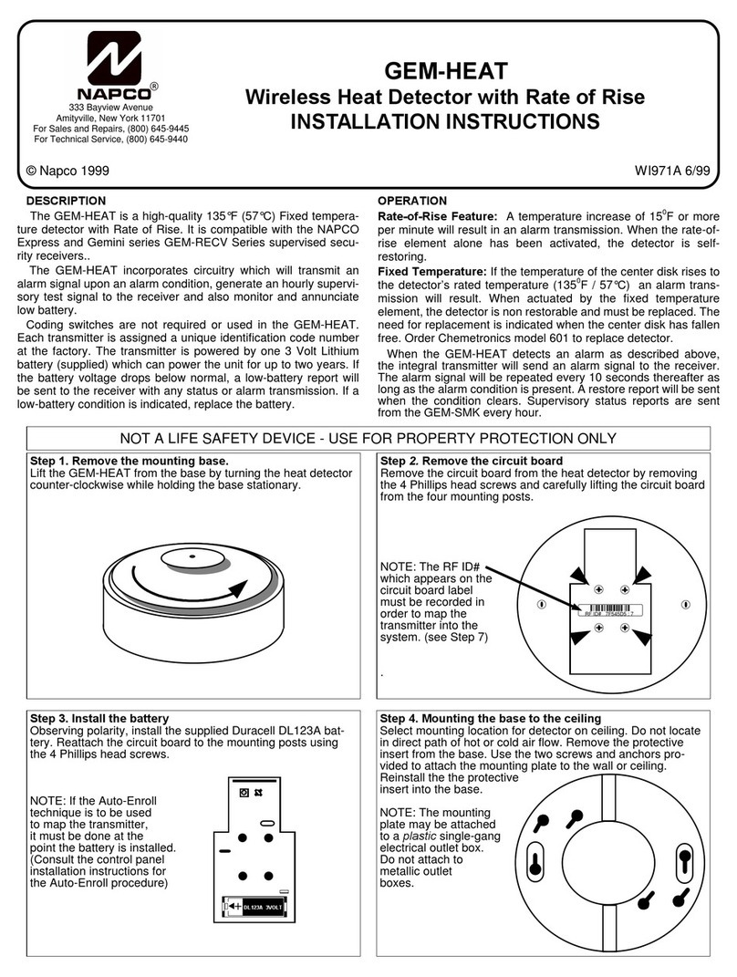
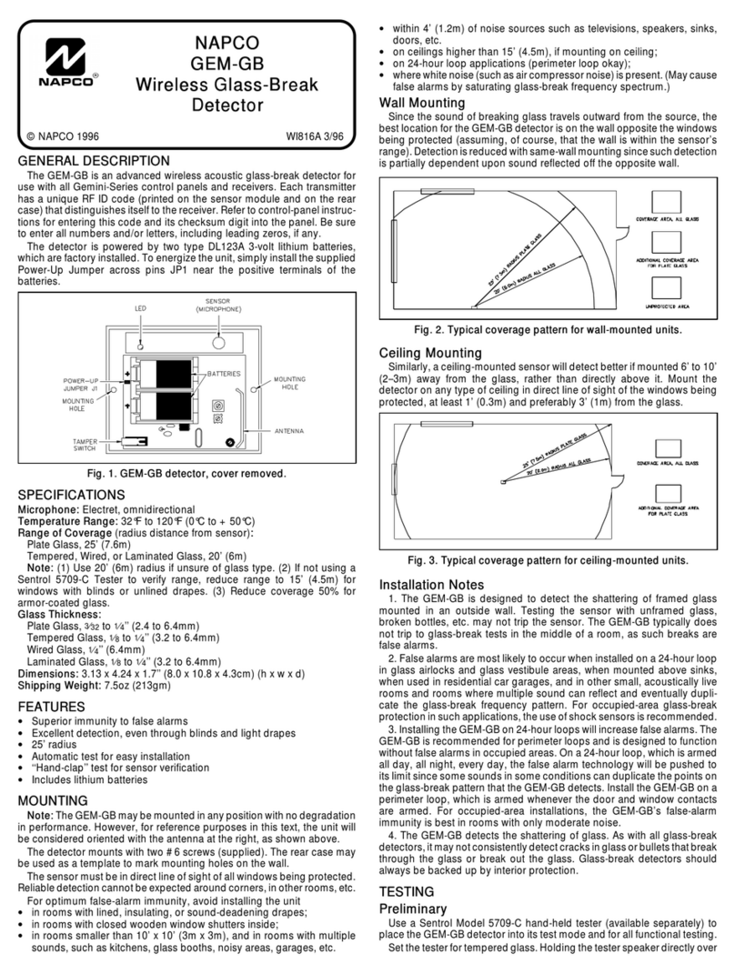
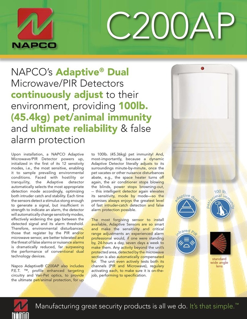
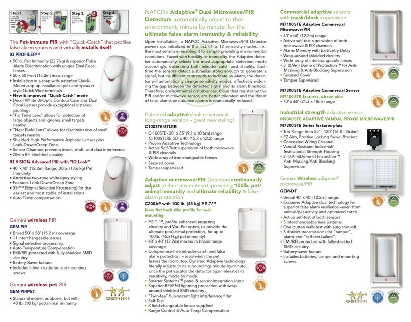
NAPCO GEMC-WL-CO User manual

1
GEMC-WL-CO Supervised Wireless Carbon Monoxide Detector Installation Instructions
OVERVIEW
The GEMC-WL-CO is a high-quality UL 2075 carbon
monoxide (CO) detector with built-in supervised digital-
ly-coded radio transmitter. It is compatible with Nap-
co's GEM-RECV and GEMC-RECV Series supervised
receivers that monitor alarms, restores, low battery,
tamper and status. Note: See Control Unit installation
instructions for compatibility.
During normal operation, when unit is in standby mode
and is within proper sensitivity limits, the green LED on
the GEMC-WL-CO flashes once every 10 seconds.
When CO is detected, the GEMC-WL-CO sounds a
local alarm and the transmitter sends an alarm signal
to the supervised receiver. The alarm signal is repeat-
ed as long as CO is still present. A restore report is
sent when the CO detection chamber clears. Supervi-
sion status reports are sent from the GEMC-WL-CO
every minute.
Note: Coding switches are not required or used in
the GEMC-WL-CO; each transmitter is assigned a
unique identification code number at the factory.
The GEMC-WL-CO must be installed in accordance
with the National Fire Protection Association (NFPA)
Standard 720.
INSTALLATION STEPS
1. Remove the Mounting Plate. Remove the
GEMC-WL-CO Mounting Plate by turning the Plate
counter-clockwise and pulling it up.
2. Identify components. Examine the GEMC-WL-
CO to identify the component locations. Take note
of the "Tamper Lock" tab located on the inside of
the Mounting Plate (see image below). Optionally,
cut this "Tamper Lock" tab to prevent the removal
of the GEMC-WL-CO from the Mounting Plate
without using a tool (such as a screwdriver).
3. Install battery. Place one 3-volt lithium Duracell,
Panasonic, Varta or Sanyo type "123A" battery in
its compartment, observing correct polarity. Enroll
the GEMC-WL-CO into the control panel before
mounting. During power up and status initializa-
tion, both the green and red LED's blink four times
every 10 seconds in unison. Then look for the
"standby" indication where the green LED blinks
once every 10 seconds.
Low Battery Warning
The CO detector and transmitter are powered by
one 3-volt lithium battery (supplied) that can power
WI2118 04/15
"Tamper Lock"
(Optional): Cut
tab to prevent
removal without a
tool
333 Bayview Avenue
Amityville, New York 11701
For Sales and Repairs, (800) 645-9445
For Technical Service, (800) 645-9440 or visit us at
http://tech.napcosecurity.com/
(Note: Technical Service is for security professionals only)
Publicly traded on NASDAQ Symbol: NSSC
© NAPCO 2015
GEMC-WL-CO
SUPERVISED WIRELESS CARBON MONOXIDE DETECTOR
INSTALLATION INSTRUCTIONS
LEAVE THESE INSTRUCTIONS WITH THE SYSTEM OPERATOR
(–)
(+)
3-VOLT BATTERY
COMPARTMENT
Lift to
remove the
Mounting
Plate
Twist the
Mounting
Plate to
unlock
Mounting
Plate

2 GEMC-WL-CO Supervised Wireless Carbon Monoxide Detector Installation Instructions
the unit for at least one year. If battery voltage
drops below normal, the red LED will flash every
45 seconds and a low battery report will be sent to
the control panel. If the voltage is still below nor-
mal after 7 days, the detector sounder will chirp.
The battery should be replaced immediately. Op-
eration of the detector cannot be assured after an
additional 7 days of low-battery indication. A low-
battery report is sent to the receiver with any status
transmission.
NOTE: Temperature and humidity extremes
may reduce the life of the battery.
Use Only Battery Specified In Marking. Use of A
Different Battery May Have A Detrimental Effect
On Detector Operation.
4. Pick CO-detector location. The GEMC-WL-CO
must be installed in accordance with the National
Fire Protection Association (NFPA) Standard 720.
Refer to figures in "Recommended Installation Lo-
cations" (on page 3) and all text on pages 3 and
4.
Note: Mounting the GEMC-WL-CO on foil-backed
wallpaper is NOT recommended because the radio
range will be reduced.
5. Install mounting plate. Use two screws and
hardware appropriate for the mounting surface to
secure the mounting plate to the wall or ceiling.
NOTE: Do not install on removable surfaces
such as ceiling tiles.
6. Map the GEMC-WL-CO Transmitter. Referring
to the installation instructions for the control panel
and keypad in use, enter the following:
the zone to which the transmitter will be
mapped
the 6-digit RF identification number / 1-digit
checksum number printed on the transmitter
(include all numbers and/or letters and leading
zeros, if any)
the transmitter point number "1"
7. Attach the GEMC-WL-CO to Mounting Plate.
Match up alignment tabs on the detector and the
Mounting Plate. Turn detector clockwise until it
locks into place (see next image).
8. Test system weekly with unit mounted and by
pressing the TEST button (shown in next image).
Perform the FUNCTIONAL GAS TEST annually (if
required by the AHJ) as described in the next sec-
tion.
FUNCTIONAL GAS TEST MODE
Note: Check with local codes and the AHJ to deter-
mine if a functional gas test is desired for an installa-
tion. If the system is monitored, notify central station
Use screw anchors for wallboard (This side to
ceiling)
DINING
ROOM KITCHEN BEDROOM BEDROOM
LIVING
ROOM BEDROOM
Twist the
detector
clockwise to
lock to the
Mounting Plate
Match up
alignment
tabs
CO Entry Ports
Test button

3
GEMC-WL-CO Supervised Wireless Carbon Monoxide Detector Installation Instructions
of the impending test.
A canned CO testing agent may be used to verify the
ability of the GEMC-WL-CO to sense CO by utilizing
the Functional Gas Test Mode. To perform the func-
tional gas test, follow these steps:
a. With a small screwdriver, depress and hold the
recessed "TEST" button for approximately 2 sec-
onds. The detector will temporarily go into alarm
and the red LED will illuminate.
b. Within a few seconds the green LED will start to
blink rapidly indicating the detector is in a speed
up, functional test mode, awaiting gas entry.
c. Spray a very small amount of Solo brand C6
canned CO into one of the 3 small gas entry holes
located on the top center of the detector.
d. Upon successful gas entry and if functioning
properly, the detector will alarm by sounding in a
Temporal-4 pattern with the red LED blinking. An
alarm signal will be sent to the control panel,
providing verification of the alarm signal.
e. The alarm condition at the detector will time out in
20 to 60 seconds or when the CO gas has
cleared.
f. If gas entry is unsuccessful, the test will time out
after 27 seconds.
VISIBLE & AUDIBLE INDICATIONS
(In priority order, starting with highest priority)
Red and green LED blink every 10 seconds for a
total of 4 times (no sound produced) = "Power On
Reset" condition.
Sounder and red LED on once a second = Carbon
Monoxide Alarm! The control panel produces
the standard CO Alarm repeating cadence of "4
beeps, 5-second pause, 4 beeps", repeatedly, until
the CO condition is cleared. To Temporarily Si-
lence: Press and hold the recessed TEST /
HUSH button for 10 seconds to temporarily si-
lence the unit for 5 minutes.
Red LED blinks once every 5 seconds; sounder
chirp every 45 seconds = CO Trouble / Calibra-
tion. (Note: Transmits a trouble to the control
panel).
Green LED blinks once every 10 seconds = Tam-
per condition. (Note: Transmits a trouble to the
control panel).
Red LED blinks once every 10 seconds; sounder
chirp every 45 seconds = End of Life Warning.
The unit has reached the end of its operational life
and will no longer detect the presence of carbon
monoxide. The unit can NOT be made operational
and therefore MUST be replaced. (Note: Transmits
A CO detector should be located in every sleeping
area, in each of the other family living units, but
just outside the kitchen.
In family living units with more than
one sleeping area, a CO detector
should be provided for each separate
sleeping area.
BEDROOM
HALL
LIVING
ROOM DINING
ROOM
BASEMENT
BEDROOM
BASEMENT
LIVING ROOM
BED
ROOM BED
ROOM
HALL
RECREATION ROOM
Indicates required CO detector
Indicates optional CO detector if
door is not provided between Living
and Recreation rooms.
Install a carbon
monoxide alarm in
the basement and on
each floor except the
attic or a storage
area.
RECOMMENDED INSTALLATION LOCATIONS

4 GEMC-WL-CO Supervised Wireless Carbon Monoxide Detector Installation Instructions
a trouble to the control panel).
Red LED blinks once every 45 seconds; chirps after
7 days = Low Battery. Chirp Silence: Press re-
cessed TEST / HUSH button to temporarily disable
the Low Battery Chirp ("sleep") for 12 hours.
Green LED blinks every 10 seconds (sounder is
silent) = Normal standby operation.
CO ALARM PROCEDURE
When a carbon monoxide alarm occurs:
1. Immediately evacuate the premises and move to
fresh air, either outdoors or by an open door or
window.
2. Call emergency services (Fire Department or 911)
3. Ensure that all persons previously within the
premises are accounted for. Do not re-enter the
premises until authorized by emergency ser-
vice responders.
4. If the CO alarm reactivates, repeat steps 1-3 and
call a qualified service technician to investigate all
possible sources of carbon monoxide, such as
from fuel burning appliances and other equip-
ment, and repair all problems found immediately.
Note any equipment not inspected and refer to the
equipment manufacturer's documentation, or con-
tact the manufacturer's directly for more infor-
mation about how the equipment can leak carbon
monoxide into the premises. Ensure all motor
vehicles are not, and have not been, operating in
an attached garage, operating adjacent to the
premises, or operating next to ventilation fresh air
intake vents. Never restart the source of a CO
problem until it has been corrected.
5. If the CO condition that caused the alarm contin-
ues, the alarm will reactivate. Never ignore the
sound of the alarm! If the CO alarm resounds, the
detector is sensing levels of CO that can quickly
become a dangerous situation. EVACUATE IM-
MEDIATELY (repeat steps 1-4).
MAINTENANCE
To keep your detector in functioning correctly, you
must:
Test the unit once a week by pressing the Test/
Hush button (insert a non-conductive pointed ob-
ject, such as a toothpick)
Carefully vacuum the unit cover once a month to
remove accumulated dust
Never use detergents or solvents to clean the unit.
Chemicals can permanently damage or temporarily
contaminate the sensor
Do not spray air fresheners, hair spray, paint or
other aerosols near the unit
Do not paint the unit, as paint will seal the vents
and interfere with proper sensor operation
Move the CO detector to a safe and remote location to
prevent damage or contamination prior to performing
any of the following:
Staining or stripping floors or furniture, painting or
wall-papering
Using aerosols or adhesives
Note: A Tamper / Trouble signal will be sent to the
control panel when the detector is removed from the
base. IMPORTANT: Reinstall the CO detector as
soon as possible to assure continuous protection.
The following lists possible substances that at some
levels can damage the sensor or cause false alarms:
Ethylene, ethanol, alcohol, iso-propanol, benzene,
toluene, ethyl acetate, hydrogen, hydrogen sulfide
and sulfur dioxide
Most aerosol sprays, alcohol based products,
paint, thinners, solvents, adhesives, hair spray,
after shave, perfume, auto exhaust, cleaning
agents, etc.
LOCATIONS TO AVOID
IMPORTANT: Improper mounting locations can
damage the electronic components within the detector.
To avoid damage, to provide optimum performance
and to avoid false alarms, proceed as follows:
Do NOT install in kitchens, garages, furnace rooms
or in areas that may expose the sensor to sub-
stances that could damage or contaminate it
Do NOT install in areas where the temperature is
colder than 32°F (0°C) or hotter than 122°F (49°C)
such as crawl spaces, attics, porches and garages
Do NOT install within 5 feet of heating or cooking
appliances. (we recommend 15 feet to prevent
false alarms)
Do NOT install near vents, flues, chimneys or any
forced/unforced air ventilation openings
Do NOT install near ceiling fans, doors, windows
or areas directly exposed to the weather
Do NOT install in dead air spaces, such as peaks
of vaulted ceilings or gabled roofs, where CO may
not reach the sensor in time to provide early warn-
ing
Do NOT install this unit near deep-cell large batter-
ies, as these batteries may have emissions that
can cause the detector to perform at less than opti-
mum performance
Do NOT obstruct the vents located on the unit
Do not mount the unit where drapes, furniture or
other objects can block the flow of air to the detec-
tor

5
GEMC-WL-CO Supervised Wireless Carbon Monoxide Detector Installation Instructions
GENERAL WARNINGS
Read these installation instructions in their entirety
before installing the GEMC-WL-CO detector.
Leave these instructions with the owner/user of the
detector.
The GEMC-WL-CO is intended for use in indoor
locations only
Failure to properly install, test and/or maintain the
GEMC-WL-CO may cause it to fail, potentially re-
sulting in loss of life
Installation of this detector is not a substitute for
proper installation, use, and maintenance of fossil
fuel-burning appliances, including appropriate ven-
tilation and exhaust systems
To reduce the risk of carbon monoxide poisoning,
test detector operation weekly
Do not paint the detector
Carbon monoxide detectors are NOT smoke detectors.
A carbon monoxide detector is NOT a substitute for
smoke detectors. This carbon monoxide detector is
specifically designed to detect the presence of carbon
monoxide gas and is NOT designed nor intended to
detect smoke, fire or any other gas. In addition, this
detector will only indicate the presence of carbon mon-
oxide at the sensor; carbon monoxide gas may be pre-
sent within other areas of the premises.
CARBON MONOXIDE POISONING
The following are some of the possible carbon monox-
ide poisoning symptoms that should be presented to
and discussed with all occupants of the protected
premises:
Mild exposure: "Flu-like" symptoms, including
but not limited to slight headache, nausea, vomit-
ing, fatigue, runny nose and sore eyes
Medium exposure: Severe throbbing head-
ache, dizziness, drowsiness, confusion, fast heart
rate
Extreme exposure: Loss of consciousness,
brain damage, convulsions, cardio-respiratory fail-
ure, death
Often cases of reported CO poisoning indicate that
while victims are aware they are unwell, they become
so disorientated that they are unable to save them-
selves by either exiting the building or calling for assis-
tance. Young children and pets may be the first affect-
ed.
SOURCES OF CARBON MONOXIDE
Potential carbon monoxide sources include fuel-fired
appliances (space heaters, furnaces, water heaters,
ranges, ovens, clothes dryers); other sources
(kerosene-burning stove or heater, or gas log fire-
place); or internal combustion engines. In addition,
excessive exhaust spillage or reverse venting of fuel-
burning appliances can produce dangerous transient
levels of CO. This can be caused by external condi-
tions, such as:
Wind direction, velocity, or a combination of both,
including high gusts of wind or insufficient draft in
vent pipes
Temperature inversions that can trap exhaust gas-
es near the ground
Negative pressure differential resulting from the
use of exhaust fans
Simultaneous operation of several fuel-burning ap-
pliances competing for limited internal air
Vent pipe connections vibrating loose from dryers,
furnaces, or water heaters
Obstructions in vent pipes or unconventional vent
pipe designs that can amplify the above situations
Poorly designed or maintained chimneys and/or
vents
Extended operation of unvented fossil fuel-burning
devices (range, oven, fireplace, etc.)
Idling cars in an open or closed attached garage,
or near the premises
GENERAL LIMITATIONS
OF CARBON MONOXIDE DETECTORS
This detector is designed to protect individuals from
the severe effects of CO exposure. It will not fully
safeguard individuals with specific medical conditions.
If in doubt, consult a medical practitioner.
If the unit is in trouble or has arrived at the end of its
life, it may not sense CO and cannot be relied upon to
monitor CO levels. Replace the CO detector by the
date specified on the unit or when the detector indi-
cates an end of life condition, whichever comes first.
CO detectors are not a substitute for designated life
safety devices. Napco does not warrant or imply in
any way that a CO detector will protect lives from CO
poisoning. These detectors should only be considered
as an integral part of a comprehensive safety program.

6 GEMC-WL-CO Supervised Wireless Carbon Monoxide Detector Installation Instructions
SPECIFICATIONS
Electrical Ratings
Input Power: Powered by a 3-volt lithium
battery. Use one 3-volt lithium
Duracell DL123A, Varta
CR123A, Panasonic CR123A
or Sanyo CR123A.
Dimensions (W×L×D) 5-3/8 x 5-3/8 x 2-1/8" (13.7 x
13.7 x 5.4cm)
Operating Environment
Temperature 32°F to 122°F (0°C to 49°C)
Relative humidity 15% - 95% RH
Regulatory Information
Manufacturer: Napco Security Technologies,
Inc. 333 Bayview Avenue,
Amityville, NY 11701
UL rating This detector has been evalu-
ated to the CO detector
sensitivity limits of UL 2075 /
UL 2034.
Environmental class Indoor, in accordance with the
Operating Environment speci-
fications.

7
GEMC-WL-CO Supervised Wireless Carbon Monoxide Detector Installation Instructions
NOTES

8 GEMC-WL-CO Supervised Wireless Carbon Monoxide Detector Installation Instructions
RADIO AND TELEVISION INTERFERENCE
This equipment has been tested and found to comply with the limits for a Class B digital device, pursuant to Part 15 of the FCC rules.
These limits are designed to provide reasonable protection against harmful interference in a residential installation. This equipment gener-
ates, uses and can radiate radio frequency energy and, if not installed and used in accordance with the instructions, may cause harmful
interference to radio communications. However, there is no guarantee that interference will not occur in a particular installation. If this
equipment does cause harmful interference to radio or television reception, which can be determined by turning the equipment off and on,
the user is encouraged to try to correct the interference by one or more of the following measures:
Reorient or relocate the receiving antenna.
Increase the separation between the equipment and the receiver.
Connect the equipment into an outlet on a circuit different from that to which the receiver is connected.
Consult the dealer or an experienced radio/TV technician for help.
Changes and Modifications not expressly approved by Napco can void your authority to operate this equipment under Federal Communi-
cations Commissions rules.
NAPCO LIMITED WARRANTY
NAPCO SECURITY SYSTEMS, INC. (NAPCO) warrants its
products to be free from manufacturing defects in materials and
workmanship for thirty-six months following the date of manufacture.
NAPCO will, within said period, at its option, repair or replace any
product failing to operate correctly without charge to the original
purchaser or user.
This warranty shall not apply to any equipment, or any part thereof,
which has been repaired by others, improperly installed, improperly
used, abused, altered, damaged, subjected to acts of God, or on
which any serial numbers have been altered, defaced or removed.
Seller will not be responsible for any dismantling or reinstallation
charges.
THERE ARE NO WARRANTIES, EXPRESS OR IMPLIED, WHICH
EXTEND BEYOND THE DESCRIPTION ON THE FACE HEREOF.
THERE IS NO EXPRESS OR IMPLIED WARRANTY OF
MERCHANTABILITY OR A WARRANTY OF FITNESS FOR A
PARTICULAR PURPOSE. ADDITIONALLY, THIS WARRANTY IS IN
LIEU OF ALL OTHER OBLIGATIONS OR LIABILITIES ON THE
PART OF NAPCO.
Any action for breach of warranty, including but not limited to any
implied warranty of merchantability, must be brought within the six
months following the end of the warranty period.
IN NO CASE SHALL NAPCO BE LIABLE TO ANYONE FOR ANY
CONSEQUENTIAL OR INCIDENTAL DAMAGES FOR BREACH OF
THIS OR ANY OTHER WARRANTY, EXPRESS OR IMPLIED, EVEN
IF THE LOSS OR DAMAGE IS CAUSED BY THE SELLER'S OWN
NEGLIGENCE OR FAULT.
In case of defect, contact the security professional who installed and
maintains your security system. In order to exercise the warranty, the
product must be returned by the security professional, shipping costs
prepaid and insured to NAPCO. After repair or replacement, NAPCO
assumes the cost of returning products under warranty. NAPCO shall
have no obligation under this warranty, or otherwise, if the product has
been repaired by others, improperly installed, improperly used,
abused, altered, damaged, subjected to accident, nuisance, flood, fire
or acts of God, or on which any serial numbers have been altered,
defaced or removed. NAPCO will not be responsible for any
dismantling, reassembly or reinstallation charges.
This warranty contains the entire warranty. It is the sole warranty
and any prior agreements or representations, whether oral or written,
are either merged herein or are expressly canceled. NAPCO neither
assumes, nor authorizes any other person purporting to act on its
behalf to modify, to change, or to assume for it, any other warranty or
liability concerning its products.
In no event shall NAPCO be liable for an amount in excess of
NAPCO's original selling price of the product, for any loss or damage,
whether direct, indirect, incidental, consequential, or otherwise arising
out of any failure of the product. Seller's warranty, as hereinabove set
forth, shall not be enlarged, diminished or affected by and no
obligation or liability shall arise or grow out of Seller's rendering of
technical advice or service in connection with Buyer's order of the
goods furnished hereunder.
NAPCO RECOMMENDS THAT THE ENTIRE SYSTEM BE
COMPLETELY TESTED WEEKLY.
Warning: Despite frequent testing, and due to, but not limited
to, any or all of the following; criminal tampering, electrical or
communications disruption, it is possible for the system to fail to
perform as expected. NAPCO does not represent that the product/
system may not be compromised or circumvented; or that the product
or system will prevent any personal injury or property loss by burglary,
robbery, fire or otherwise; nor that the product or system will in all
cases provide adequate warning or protection. A properly installed
and maintained alarm may only reduce risk of burglary, robbery, fire or
otherwise but it is not insurance or a guarantee that these events will
not occur. CONSEQUENTLY, SELLER SHALL HAVE NO LIABILITY
FOR ANY PERSONAL INJURY, PROPERTY DAMAGE, OR OTHER
LOSS BASED ON A CLAIM THE PRODUCT FAILED TO GIVE
WARNING. Therefore, the installer should in turn advise the consumer
to take any and all precautions for his or her safety including, but not
limited to, fleeing the premises and calling police or fire department, in
order to mitigate the possibilities of harm and/or damage.
NAPCO is not an insurer of either the property or safety of the
user's family or employees, and limits its liability for any loss or
damage including incidental or consequential damages to NAPCO's
original selling price of the product regardless of the cause of such
loss or damage.
Some states do not allow limitations on how long an implied
warranty lasts or do not allow the exclusion or limitation of incidental
or consequential damages, or differentiate in their treatment of
limitations of liability for ordinary or gross negligence, so the above
limitations or exclusions may not apply to you. This Warranty gives
you specific legal rights and you may also have other rights which vary
from state to state.
NAPCO SECURITY TECHNOLOGIES, INC.
333 Bayview Avenue, Amityville, New York 11701 For Sales and Repairs, (800) 645-9445 For Technical Service, (800) 645-9440 or visit us at http://tech.napcosecurity.com/
(Note: Technical Service is for security professionals only)
Publicly traded on NASDAQ Symbol: NSSC
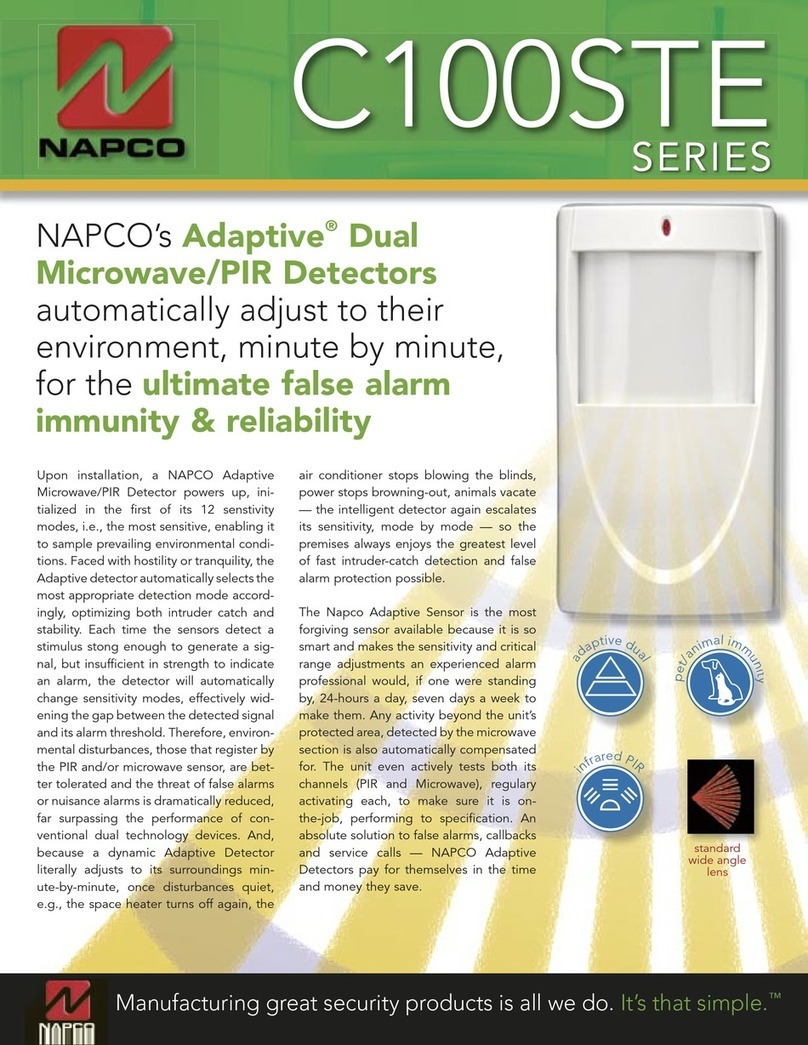
Table of contents
Other NAPCO Security Sensor manuals

NAPCO
NAPCO PIR 1500-10 User manual

NAPCO
NAPCO GEM-HEAT User manual

NAPCO
NAPCO GEM-GB User manual

NAPCO
NAPCO IQ PROFILER - User manual

NAPCO
NAPCO PIR1680 Series User manual

NAPCO
NAPCO C 200 AP User manual

NAPCO
NAPCO PIR1680 User manual

NAPCO
NAPCO C 100 SAFARI User manual

NAPCO
NAPCO GEMC-NL-MOD User manual

NAPCO
NAPCO C 1000 STE User manual
Popular Security Sensor manuals by other brands

Niko
Niko 350-20061 manual

ITALIANA SENSORI
ITALIANA SENSORI 8032-ISR023 Installation, operation and maintenance manual

Conrad Electronic
Conrad Electronic 182622 operating instructions

Honeywell
Honeywell Fire Sentry FS7-2173-2RP Installation guide and operating manual

Jung
Jung DWPM17360AL manual

PLS
PLS SLD operating manual