Watermaid WM10LED User guide

2005
Owner's Handbook
PROVEN PERFORMANCE SINCE 1971
POOL CHLORINATION WITH SALT
WM10LED
PROVEN PERFORMANCE SINCE 1971
POOL CHLORINATION WITH SALT
2005
important
please read
instructions
before use
For technical service or advice, contact:
AUSTRALIA
SYDNEY (HEAD OFFICE) - Watermaid Pty Ltd
24 Tepko Rd Terrey Hills NSW 2084
Ph: +61 2 9450 0244
ADELAIDE - Watermaid Pool Chlorinators
190 Hart Street Ethelton SA 5015
Ph: +61 8 8242 4880
CANADA
ONTARIO - Watermaid of Canada Inc.
Ph: +1 877 987 6243
SOUTH AFRICA
JOHANNESBURG - Aussie Concepts
Unit 3, 170 Bernie St Kya Sand
Ph: +27 11 794 1770
U.S.A.
FLORIDA - Watermaid USA Inc.
Suite 404, 7361 International Pl
Sarasota 34240
Ph: 800 737 3390 or +1 941 907 8982
HAWAII - Aloha Salt Pools
Ph: +1 808 262 7258
AUSTRIA - FED Fiedler
Ph: +43 7229 831 7466
CANARY ISLANDS - PyLys
Ph: +34 922 491252
CYPRUS - Eco Technology Pools
Ph: + 44 1536 39523
MARTINIQUE - Azur Carrell Decor
Ph: +596 612 072
SPAIN - JB Supplies
Ph: +34 636 698501
SWITZERLAND - Salzwasser PoolWorld
Ph: +417 1290 0888
U.K. - Barchem Pools Ltd
Ph: +44 1793 861168
MODEL WM10LED
for use on swimming pools & spas
Australian Approval N13477
Registration No. 28114
Pest Control Products Act (PCPA)
Conforms to: AS3136, UL STD 1081
Certified to: CAN/CSA STD C22.2
NUMBER 218.1 Class 3 Enclosure
N14470 3075239 3075239

21
1 STATUTORY RIGHTS OF
CONSUMERS
The warranty terms set out below do not
exclude any conditions or warranties
which may be mandatorily implied by law,
and your attention is drawn to the
provisions of the Australian Trade
Practices Act, 1974 and the State
legislation which confers certain rights
upon consumers. The following
WARRANTY supplements these.
2. WATERMAID WARRANTY
a)WATERMAID PTY LTD warrants to the
WATERMAID owner that the WATERMAID
Power Supply (excluding any timeclock
component) shall remain free of defects
in manufacturing or workmanship for a
period of two (2) years from the date of
purchase.
b)WATERMAID PTY LTD warrants to the
WATERMAID owner that the timeclock
component contained in the Watermaid
Power Supply shall remain free of defects
for a period of one (1) year from the date
of purchase.
c)WATERMAID PTY LTD warrants to the
WATERMAID owner that the Watermaid
Cell shall remain free of defects in
manufacturing or workmanship for a
period of 12 months from the date of
purchase. An additional 48 month pro-
rata replacement warranty applies to the
Watermaid Cell.
Any parts in a WATERMAID Power Supply
or Cell found by WATERMAID PTY LTD to
be operationally defective will be repaired
or replaced at WATERMAID PTY LTD's sole
discretion.
(d) The WARRANTY as outlined in
paragraphs 2(a), 2(b) and 2(c) above
DOES NOT apply:-
(i) To any defect or failure caused by
misuse, abuse, abrasion, buildup on Cell
electrodes, electrical faults, power surges
(including lightning strikes), harsh
chemicals, incorrect water balance, wear
and tear, accident, non-observance of
installation, operating and/or cleaning
instructions or any other conditions
outside of the control of WATERMAID PTY
LTD;
(ii) If the product has been serviced by a
person not authorised to do so by
WATERMAID PTY LTD or with non
approved parts;
(iii) If any serial number or compliance
label has been removed or defaced;
(iv) If the product has not been fully paid
for by all parties to the sale or is
repossessed under any financing
agreements.
(v) Where the Power Supply or Cell has
been subject to any use other than
NORMAL DOMESTIC POOL USE.
3. FREIGHT
Subject to the WATERMAID owner's
statutory rights referred to in clause 1,
WATERMAID PTY LTD reserves the right
to charge for any services not covered by
this WARRANTY, including freight costs.
4. OTHER LIABILITY
Subject to the WATERMAID owner's
rights referred to in Clause 1 and 2,
WATERMAID PTY LTD hereby excludes to
the maximum extent permitted by law all
other liability in respect of the product.
5. CLAIMS UNDER WARRANTY
If a defect covered by this warranty
arises, the WATERMAID owner should
contact WATERMAID PTY LTD as soon as
the defect arises and advise WATERMAID
PTY LTD of the nature of the defect.
Claims made after the warranty period
has expired will not be covered by
warranty.
Effective 1 January 2005, replaces all undated Warranties and all Warranties dated before 1 January 2005.
IMPORTANT SAFETY INSTRUCTIONS
WATERMAID ELECTROLYTIC CHLORINATOR MODEL WM10LED CHLORINE GENERATING DEVICE
DOMESTIC - FOR RESIDENTIAL POOLS & SPAS
REGISTRATION NUMBER 28114
PEST CONTROL PRODUCTS ACT
When installing and using this electrical equipment, basic safety precautions should always be
followed, including the following:
READ AND FOLLOW ALL INSTRUCTIONS IN THIS OWNERS MANUAL AND ON THE LABEL BEFORE
USING
a) To reduce the risk of electric shock, the ground wire of this device must be connected to the
grounding means provided in the electricity supply service panel with a continuous copper wire
equivalent to the circuit conductors supplying the equipment.
b) WARNING: KEEP OUT OF THE REACH OF CHILDREN.
c) WARNING: Risk of electric shock. Connect only to a grounding type receptacle protected by a
ground fault circuit-interrupter (GFCI). Contact a qualified electrician if you cannot verify that the
receptacle is protected by a GFCI.
d) Do not bury cord. Locate cord to minimise abuse from lawn mowers, hedge trimmers, and other
equipment.
e) WARNING: To reduce the risk of electric shock, replace damaged cord immediately.
To avoid
hazard, the supply cord, if damaged, must be replaced by the manufacturer or its service
agent or a similarly qualified person.
f) WARNING: To reduce the risk of electric shock, do not use an extension cord to connect unit to
electricity supply; provide a properly located outlet.
g)
CAUTION: to prevent electric shock, switch OFF the power at the electrical power outlet
before dislodging the WATERMAID Power Supply. Do NOT remove the cover as there are no
user serviceable parts inside. Refer to a qualified service technician for repair.
h) Maintain water chemistry in accordance with manufacturer's instructions.
IMPORTANT
* The WM10LED chlorinator is designed to run at a maximum salt level of 6000 ppm.
* This unit MUST be installed AT LEAST 10 feet (3m) from the inside wall of the pool.
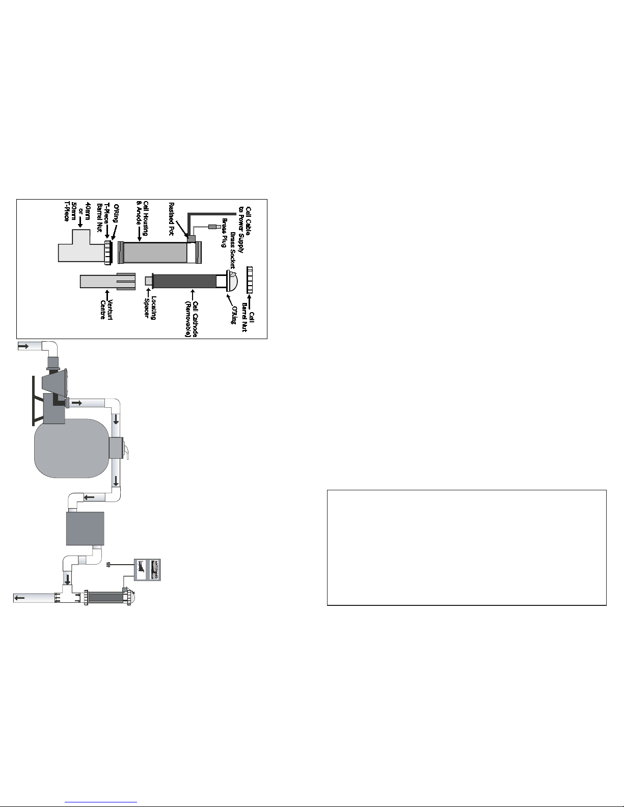
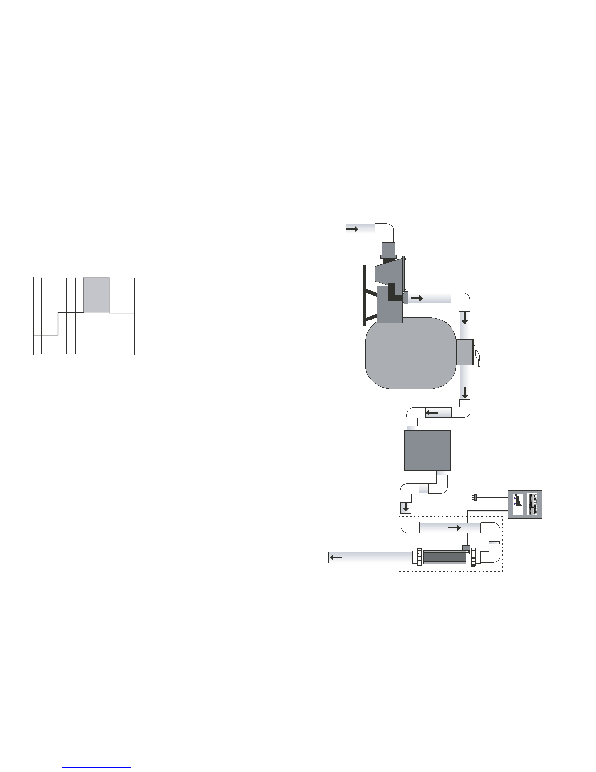
* The WATERMAID QT SERIES Cells must be installed with a gas-trap to prevent any gases
getting back into the filter.
* The WATERMAID Cell must be installed so that ALL the water from the filter passes through
the WATERMAID Cell before any diversions or breakouts.
* Ensure that the WATERMAID Power Supply is OFF or in standby mode [refer to section 4]
when adding salt to the water or water flow is restricted (e.g. backwashing the filter, blocked
skimmers, etc) [refer to section 7(vi)].
* It is recommended that between 5Kg and 25Kg per year of Magnesium [Magnesium Sulphate
("Epsom Salts") or Magnesium Chloride] be added to the pool water.
* Do NOT add any products containing Calcium to the pool water.
* Use with a pump rated at 1HP or above.
* Do NOT strike the Cell with any kind of instruments.
WARNING: Improper installation or operating the WATERMAID electrolytic chlorinator
model WM10LED without water flow through the Cell can cause a build up of flammable
gases, which can result in FIRE or EXPLOSION.
Registrant:
Watermaid Pty Ltd
24 Tepko Rd
Terrey Hills NSW 2084
Australia
Ph: +61 2 9450 0244
Retain Owner's Handbook for future reference.
Canadian Agent:
Watermaid of Canada Inc.
16 Blyth St
Richmond Hill Ontario L4E-2Y1
Canada
Ph: +1 877 987 6243

20
1. Essentials for a healthy pool...........................................
a) Filtration...........................................................
b) Chlorination.......................................................
c) pH....................................................................
2. The chemistry involved..................................................
3. Installation...................................................................
i) Measure the pool or spa size..............................
ii) Adding salt to the pool or spa.............................
iii) Mount the Power Supply....................................
iv) Install the WATERMAID Cell*..............................
v) Attach Cell to Power Supply...............................
vi) Connect to the power outlet...............................
* EZ300 Series Cell - Installation Diagram.............................
* QT Series Cell - Vertical Installation Diagram.......................
* QT Series Cell - Horizontal Installation Diagram...................
4. The Power Supply..........................................................
5. Auto Cell Cleaning.........................................................
6. The Timeclock..............................................................
7. The Cell.......................................................................
8. Salt Level.....................................................................
9. Running Times..............................................................
10. Chlorine Depletion.........................................................
11. The Langlier Index........................................................
12. Algae...........................................................................
13. Electricity Costs............................................................
Troubleshooting..................................................................
Warranty...........................................................................
2
2
2
3
3
4
4
4
5
5
5
5
6
7
8
9
10
10
11
13
14
14
15
16
17
18
21
WM10 Power Supply
(timeclock optional)
EZ300 Cell
(Patented Design)
QT300/QT400
Cells
This Owner's Handbook contains information relating to WATERMAID salt water
chlorinators as well as general pool maintenance. Pictured below are the current models
of WATERMAID chlorinators available for swimming pools.

19
POOR CIRCULATION
* Dirty and clogged filter
* Skimmer baskets full of leaves, hair, debris etc
* Faulty pump
* Low speed pump
* Water level is low
* Cell is clogged with scale [refer to section 7(iii)]
FILTER PROBLEM
If the WATERMAID chlorinator is capable of registering 75 - 100%, but the pool or spa water
is cloudy, there may be a filter problem.
* Filter may need backwashing [refer to section 7(vii)][also refer to filter manual]
* Insufficient running times
* Body fat or oil build up on pads
* Sand filters: The sand in a sand filter should be changed every 5 years
* Diatomaceous earth filters: Insufficient diatomaceous earth over the pads
FOR EARLIER WATERMAID MODELS
For WATERMAID models manufactured prior to 2004, a solid green light indicates the
WATERMAID is producing chlorine and functioning correctly.
If the light stays red, it indicates one or more of the following:
> a deposit has formed on the Cell electrode(s) or its sensing tang (12mm metal tang
located at the top of the electrodes on the inside of the Cell) and requires cleaning [refer
section 7(iii)], or
> there is no water flow in the Cell, or
> the Cell On/Off switch is not on, or
> the wires inside the black terminal box connecting the Cell to the Power Supply are loose,
burnt, corroded or wired together incorrectly [refer to section 3(v)] or,
> the pool's salt level is low or,
> the Cell is at the end of its life.
For WATERMAID models manufactured before 1993, if the chlorinator is not
switched OFF when adding salt to the water, then undissolved salt may pass
through the Cell and cause the Power Supply to draw a higher current than
normal. As there is no overload protection in these units, damage may result.
(Continued)
Free Available Chlorine
pH
Total Alkalinity
Pools
1.0 - 3.0 ppm
7.2 - 7.8
100 - 200 ppm
Spas
3.0 - 5.0 ppm
7.2 - 7.8
100 - 200 ppm
1. ESSENTIALS FOR A HEALTHY POOL
Recommended daily levels for swimming pools and spas as determined by a test kit.
Check the expiry date on the test kit, as test results may be inaccurate if used after that date.
There are three fundamental requirements for maintaining a swimming pool or spa:
a) FILTRATION b) CHLORINATION c) pH
A pool or spa should be looked at daily to check that the water is clean and clear and the finest
details of the pool or spa walls can be seen at the deepest part. This will indicate whether the
pool or spa has had enough filtration and chlorination for the load conditions that were
applicable the day before. Any other condition requires testing and rectification before entering
the water.
a) FILTRATION
It is first necessary to pass water through a filter to remove debris. A standard sized pool pump
with normal filter pressures will pump about 10,000 litres (2,642 gal) an hour, so an average
60,000 litre (15,850 gal) pool then requires six to ten hours of filtration a day in summer
conditions. This will turn over the equivalent of 1 1/2times the total volume of water. However,
about 65% only of the actual water and debris will have passed through the filter. For
spas, the water typically turns over several times per hour with all of the water also going through
a filtration system (refer to owner's manual for details).
b) CHLORINATION
The WATERMAID pool chlorinator takes care of the chlorination. As mild saline water flows
through the WATERMAID Cell it is converted, by electrolysis, into chlorine as sodium hypochlorite.
Chlorine is required after filtration to react with any remaining debris (both visible and invisible),
remove stains by oxidation and sterilise the water of harmful bacteria.
A chlorine residual (or reserve) is required for any imminent bather load. A total of 1 to 3 ppm of
free available chlorine for pools and 3 to 5 ppm of free available chlorine for spas is required to
maintain a clean clear condition.
Because of its instability, chlorine has a half-life of some 35 minutes in strong sunlight and
even less in the presence of contaminants. Therefore, the use of a chlorine stabiliser is
strongly recommended as it lengthens the half-life of chlorine to about 140 minutes and helps
maintain a chlorine residual in the pool on hot sunny days. At the beginning of the summer
season, chlorine stabiliser (Iso-cyanuric acid) should be added to the pool and circulated by
filtration.
Generally, at dawn and at dusk, wind dies down and
these are the best times to commence filtration.
Leaves and floating debris will be swept to the
skimmer box without restriction if the pool is well
designed.
Longer filtration cycles can reduce the chlorine
requirement and conversely, more chlorine can reduce
the filtration requirement.
For an average 60,000 litre (15,850 gal) pool, add 2
1/2Kgs (approx. 6 lb) of chlorine stabiliser. After this
initial dose, the pool should be topped up with chlorine
stabiliser throughout the hot summer period to
maintain a level between 30 and 50 ppm. Factors
such as sunlight, filter and pump efficiency, stabiliser
level, bather load, debris, water temperature, salt
level, water level, chemical balance and age of the
Cell, ALL AFFECT THE FINAL CHLORINE LEVEL.
2
FILTER & PUMP
60,000L
or
15850 gal
10,000 L / hr
2,642 gal / hr
6 - 10 hours / day
Recommended chlorine
stabilizer level: 30 - 50 ppm
Do NOT exceed 80 ppm
Note:
Indoor pools do not
require the addition of
chlorine stabilizer. Nor
do spas due to the
high turnover rate of
the water.

The following is a list of possible causes to commonly encountered problems.
CHLORINE RESIDUAL LOW OR NIL
* Not enough chlorine being produced [refer to section 7(i)]
* Heavy bather load - insufficient running times to cope [refer to section 9]
* Strong sunlight conditions and/or insufficient chlorine stabiliser level [refer to section 1(b)]
* pH too high or low [refer to section 1(c)]
* Poor water circulation [refer below]
* Algacide has been added within the last 4 weeks [refer to section 12]
* Excessive calcium level causing scale on Cell electrodes [refer to sections 5 & 7(iii)]
* Cell is old and needs replacing [refer to section 7(v)]
CHLORINE LEVELS HIGH IN THE MORNING AND NIL AT NIGHT
* Heavy bather load [refer to section 9]
* Extreme sunlight conditions and/or insufficient chlorine stabiliser level [refer to section
1(b)]
RED LIGHT
* Nil or insufficient water flow in Cell or poor circulation [refer below]
* Problem with Cell connection [refer section 3(v)]
* Excessive calcium level causing scale on gas sensor [refer to sections 4, 5 & 7(iii)]
NO GREEN LIGHTS
* Low salt level [refer to section 3(ii) and 8]
* Excessive calcium level causing scale on Cell electrodes [refer to sections 5 & 7(iii)]
* End of Cell life [refer to section 7(v)]
* Problem inside Power Supply - refer to qualified service technician for repair
NO LIGHTS AT ALL
* No power to WATERMAID chlorinator [refer to section 3(vi)]
* Timeclock incorrectly set or faulty [refer to section 6]
* Problem inside Power Supply - refer to qualified service technician for repair
SCALE BUILD-UP ON CELL ELECTRODES [for removal refer to section 7(iii)]
* Excessive calcium level in water [refer to section 5]
* Insufficient Magnesium level in water
PH ALTERS RAPIDLY AND EASILY
* Low total alkalinity in marblesheen, pebbled, quartzon or tiled pools or spas and may be
the result of contamination [e.g. debris, urine etc][refer to section 1(c) and section 11]
18
3
Ideal Range
7.2 - 7.8
c) pH
pH refers to the acid/alkaline balance of the water. pH 14 is alkaline, 0 is acid and 7 is neutral.
Within the pH range 7.2 to 7.8 chlorine will work effectively as a sanitizer, and the
precipitates formed will be at their maximum size and easily picked up by the filter.
At pH 8.0, chlorine is only 21% effective and greater than 8.0 the water is alkaline and can cause
skin rashes. Below 7.0 monochloramines are formed and will sting sensitive skin and eyes.
Marblesheen, pebbled, quartzon and tiled pools and spas stabilise naturally between pH
7.6 and 8.2 so the effects of chlorine are disadvantaged. For these pools and spas it is
recommended that pH buffer (sodium bicarbonate) be used as this will help stabilise the pH
between 7.6 and 7.8 as well as raise the total alkalinity.
Total alkalinity is a measure of the alkaline chemicals in the water such as bicarbonates and
carbonates. Keeping the total alkalinity between 150 and 200 ppm will help keep the pH
below 7.8 (to achieve the desired total alkalinity, refer to tables, section 11).
Adding sodium bicarbonate will also help to protect newly-surfaced marblesheen, pebbled,
quartzon and tiled pools and spas, as it will react with calcium salts and form a coating of calcium
carbonate over the surface. This in turn will slow down lime leaching out from the fresh cement
(which contains up to 60% calcium oxides), thereby making it easier to achieve the desired water
balance (measured by the Langlier Index calculation, refer to section 11). For an average sized
pool, about 10 Kg (approx. 22 lb) of sodium bicarbonate will raise the total alkalinity 80 ppm.
pH remains stable for pools and spas with inert surfaces such as fibreglass, fibreglassed
concrete, painted concrete and vinyl-lined surfaces which also have a naturally
occurring total alkalinity of 80 - 100 ppm. As this is an ideal situation, there is no need
to add pH buffer to these pools or spas.
If hydrochloric acid is used to lower pH, it should be added SPARINGLY and only according to the
instructions given by an Acid Demand Test Kit, as the acid will attack the pool and spa walls
causing the calcium level in the water to rise.
2. THE CHEMISTRY INVOLVED
The WATERMAID Cell, by electrolysis, produces
sodium hypochlorite (NaOCl). In water, sodium
hypochlorite dissociates into sodium (Na+) and
hypochlorite (OCl-) ions. It is the hypochlorite
ions that form with the hydrogen (H+) ions
(from the water) to form hypochlorous acid
(HOCl), the active agent that destroys bacteria
and algae, and oxidizes organic matter.
HOCl & THE IMPORTANCE OF pH
The chart (right) shows the effect of pH on the
reversing reaction of HOCl (hypochlorous acid) in
water.
It can be seen that HOCl is more effective as a
sterilising agent at pH levels below 7. However,
for swimming conditions it is recommended
that the pH be kept within the range of 7.2
- 7.8.
pH
1 2 3 4 5 6 7 8 9
0
20
40
60
80
100
100
80
60
40
20
0
Total % of Active HOCl molecules
Total % of OCl (hypochlorite) ions
THE EFFECT OF pH
ON THE DISSOCIATION OF
HYPOCHLOROUS ACID

floor and can then be vacuumed directly to waste (i.e. NOT through the filter). Following
this, the pool should gradually attain a clean, clear condition after constant filtration and
chlorination.
5. Finally, the use of LANTHANUM CARBONATE (or "Starver") is recommended to reduce the
phosphorous content to less than 1 part per billion. This starves algae of an essential element for
growth.
As a guide, the WATERMAID chlorinator may need to be run non-stop for several days
to overcome the addition of an algaecide containing ammonium compounds AND any
debris. Otherwise, a sufficient chlorine reading may be impossible to obtain for up to 4
weeks.
For spas, it is often best to drain, clean and refill. Follow the manufacturers recommended
procedure.
13. ELECTRICITY COSTS
When an Australian 240VAC model WATERMAID chlorinator is running at full capacity, it is using
420 watts of power.
{POWER (watts) = VOLTS X AMPS}
Therefore the cost to run a Watermaid chlorinator at full capacity is worked out using the
following formula:
COST = No. of X Hours X Cost Per
TO Watts Run kWh
RUN
1000
As an example, a WATERMAID chlorinator run for 10 hours in Sydney, where the domestic cost of
electricity is 9.71 cents/kWh, will cost a total of:
= 420 / 1000 x 10 x 9.71
= 40.782
= 41 c / day
17
Schematic Diagram
sœ‹™…Š
scr
scr
n‡”“ lƒ’• ‹“™‡‰—ƒ™‡†
‹“™” ˜œ‹™…Š
p”˜‹™‹›‡ ”š™•š™
gƒ˜ s‡“˜”— i“•š™
KOM ”š™•š™ ˆ”— …‘‡ƒ“‹“‰ …Ÿ…‘‡
Pv
c”“™—”‘
c‹—…š‹™
ac i“•š™ ˆ”— …”“™—”‘ …‹—…š‹™
ac
ac
scr gƒ™‡
scr gƒ™‡
Pv
sŠš“™ m‡ƒ˜š—‡’‡“™
sŠš“™ r‡˜‹˜™”—
t—ƒ“˜ˆ”—’‡—
Pv
ac i“•š™ ˆ”— …”“™—”‘ …‹—…š‹™
4
3. INSTALLATION
The WATERMAID chlorinator may be installed by the pool owner. However, these instructions
should be fully understood to ensure correct installation and safe operation. Incorrect
installation may pose a danger and/or may damage the unit thus voiding warranty. If there is
any doubt, then an experienced pool technician or plumber should carry out the installation.
(i) MEASURE THE POOL OR SPA SIZE
The size of the pool or spa determines the amount of salt to add. If the pool or spa is
rectangular, the length, breadth and average depth are multiplied. If the pool or spa has an
irregular shape, then the average of the measurements can be taken.
For pool water with no salt, align "0 ppm" in either of the following Metric or U.S.
Measurements tables with the column that represents the size of the pool, e.g. a 60,000 litre
pool with no salt would need 360 Kg (approx. 14 x 25 Kg bags) of salt.
For pool water containing salt, find the salt level (in ppm) using a WATERMAID hydrometer
or reading from a pool shop and align this value with the column that represents the size of
the pool, e.g. an 80,000 litre pool with a salt reading of 4000 ppm would need 160 Kg
(approx. 6 x 25 Kg bags) of salt.
Empty the contents of the required salt bags to the pool or spa. For pools, it is best to add the
salt to the shallow end and run the filter and pump simultaneously to circulate the water and
dissolve the salt. The WATERMAID should be turned OFF or to standby mode (refer to
section 4). The salt bag should NOT be thrown into the pool as chemicals and inks can
interfere with the water balance.
Quality pool salt (with low levels of iron and other
impurities) should be used. Finer grades dissolve faster.
Salt may take 24 - 48 hours to
dissolve in summer and longer in winter.
Alternatively, sea water may be used.
If the pool has no main drain, place a vacuum hose head in the deep end, and sweep the salt
toward the vacuum head. The other end of the vacuum hose should be placed in the skimmer
box. Run the filter and pump with the WATERMAID chlorinator OFF to circulate the undissolved
salt in the water.
(ii) ADDING SALT TO THE POOL OR SPA
DO NOT add pool/spa chemicals directly to the
skimmer. This may damage the Cell.
Maintaining high salt levels above the
recommended range can contribute to corrosion
of pool/spa equipment.
Watermaid
recommends a salt concentration in the
water of 6000 ppm (refer to section 8).
If the chlorinator has already been
installed, it should be turned off or to
standby mode (refer to section 4)
before
adding salt.
Average
Depth = 1.5M
Breadth = 4.5M
Length = 9M
SALT
0 ppm
1000 ppm
2000 ppm
3000 ppm
4000 ppm
5000 ppm
10000gal
500 lb
417 lb
333 lb
250 lb
167 lb
83 lb
15000gal
750 lb
625 lb
500 lb
375 lb
250 lb
125 lb
20000gal
1000 lb
833 lb
666 lb
500 lb
334 lb
167 lb
25000gal
1250 lb
1042 lb
833 lb
625 lb
417 lb
208 lb
30000gal
1500 lb
1250 lb
1000 lb
750 lb
500 lb
250 lb
POOL SIZE (U.S. MEASUREMENTS)
SALT
0 ppm
1000 ppm
2000 ppm
3000 ppm
4000 ppm
5000 ppm
40,000 L
240 Kg
200 Kg
160 Kg
120 Kg
80 Kg
40 Kg
60,000 L
360 Kg
300 Kg
240 Kg
180 Kg
120 Kg
60 Kg
80,000 L
480 Kg
400 Kg
320 Kg
240 Kg
160 Kg
80 Kg
100,000 L
600 Kg
500 Kg
400 Kg
300 Kg
200 Kg
100 Kg
120,000 L
720 Kg
600 Kg
480 Kg
360 Kg
240 Kg
120 Kg
POOL SIZE (METRIC)
SALT REQUIRED = Pool size (in litres) x 0.006
SALT REQUIRED = Pool size (in gallons) x 0.05
One bag of salt usually
contains 25 Kg or 40 lb.
Average Pool
9 x 4.5 x 1.5 m
=60,000 litres or 60 m3
or
30 x 15 x 4 feet x 6.25
=12,000 gallons

16
The ideal environment for algal growth is when
there are periods of zero chlorine. Algae blooms
can take less than a day to turn a pool or spa
green.
At the first sign of adversity, the algae
population goes into a reproduction phase to
produce SPORES. The size of these spores is
less than 0.2 microns. D.E. filters and sand
filters are able to filter 5+ microns and 20+
microns respectively.
12. ALGAE
A common problem for any type of pool or spa is algae growth. There are 24,000 known types of
algae, all distinguishable by being single-celled organisms capable of photosynthesis (they produce
their own food), mitosis (all cells can divide) and meiosis (reproduction is possible by combining
with other algal cells).
Algae will die from doses of chlorine as low as 0.05 ppm concentration, but spores can resist
chlorine levels of up to 10 ppm. Salt chlorinators do not achieve those conditions and a manual
chlorine dose would need about 1-2 Kg (2-4 pt) of hypochlorite equivalent to be effective.
Spores, however, cannot tolerate copper salts as copper attaches to the shell or
endospore preventing germination. Hence, the most effective algaecides contain copper salts.
For a few black algal spots, suspending 50 grams (approx. 2 ounces) of stabilised chlorine in a
weighted nylon bag over the trouble spots may remove them.
For a more serious algae problem in pools, it is advisable to:
1. Lower pH below 7 [generally by the addition of up to 2 litres (4 pt) of pool acid] as this is an
essential part of reducing algae resistance.
2. About 4 hours later, add a copper treatment to attain a 1 ppm copper level in the pool.
About 1 heaped tablespoon of copper sulphate (approx. 70 grams or 3 ounces) dissolved in 10
litres (approx. 3 gal) of water spread around the pool is the most economical method. But the use
of any commercial copper-based algaecide will do.
Note: Do not swim in the pool for at least 24 hours, as the copper treatment may
discolour hair and clothing.
3. After about 12 hours a stainless steel brush and a garden hose fitted with a brass jet gurney
(available from hardware stores) can be used to remove algae from the pool walls.
4. Floc the pool with a clarifier. After a few hours, a blanket of debris will settle on the pool
TO LOWER TOTAL ALKALINITY
USING LIQUID POOL ACID
(HYDROCHLORIC ACID)
50,000
395mL
580mL
1.22L
1.60L
2.00L
2.40L
2.82L
3.20L
3.60L
4.05L
75,000
554mL
1.20L
1.85L
2.40L
3.05L
3.65L
4.25L
4.85L
5.45L
6.10L
100,000
790mL
1.60L
2.45L
3.20L
4.00L
4.80L
5.65L
6.40L
7.20L
8.10L
Table A
POOL VOLUME IN LITRES
TO RAISE TOTAL ALKALINITY
USING SODIUM BICARBONATE
INCREASE
ppm
10
20
30
40
50
60
70
80
90
100
50,000
893gm
1.70Kg
2.60Kg
3.40Kg
4.30Kg
5.20Kg
6.00Kg
6.80Kg
7.80Kg
9.00Kg
75,000
1.34Kg
2.60Kg
3.90Kg
5.20Kg
6.50Kg
7.80Kg
9.10Kg
10.40Kg
11.70Kg
13.40Kg
100,000
1.79Kg
3.40Kg
5.20Kg
6.80Kg
8.60Kg
10.40Kg
12.00Kg
13.60Kg
15.60Kg
18.00Kg
Table B
POOL VOLUME IN LITRES
LOWER
ppm
10
20
30
40
50
60
70
80
90
100
U.S.
Measurements
Coversion
Formulae:
To convert from
Litres to Gallons:
x 0.2642
To convert from
Kilograms to
Pounds: x 2.205
A microscopic photo of algae
5
(iii) MOUNT THE POWER SUPPLY
The WATERMAID Power Supply should ideally be enclosed within a splash-proof housing (e.g. in a
filter box) and mounted in a position that complies with local regulations.
1. Locate a suitable position for the WATERMAID Power Supply which allows for box dimensions
of 240mm wide x 320mm high x 130mm deep (9.4 x 12.6 x 5.1 in). [Allow at least 20 mm (0.8
in) from the top of the WATERMAID Power Supply to any structure or fitting above]
2. For Brickwork:
a) Drill 2 x 8 mm (0.3 in) diameter holes, 30mm (1.2 in) deep, that are 156mm (6.1 in) apart
and level.
b) Insert 2 blue (8 mm or 0.3 inch diameter) wall plugs into the holes drilled.
c) Place the screws (provided) into the holes of the bracket (provided) and screw tight.
3. For Mounting onto Timber:
a) Drill 2 x 4mm (0.2 in) diameter holes into the timber, 30mm (1.2 in) deep, that are 156 mm
(6.1 in) apart and level.
b) Place the screws (provided) into the holes of the bracket (provided) and proceed to screw
tightly into the timber.
4. Lift the WATERMAID Power Supply onto the bracket ensuring that it is secure on the wall.
(iv) INSTALL THE WATERMAID CELL
Before installing the Cell, unplug the filter, pump and WATERMAID Power Supply. This
is advisable so that the filter will not start inadvertently if a timeclock already exists. Also, close
off the valves if the filter and pump are below pool surface level or if there are no valves, block
off the inlet and outlet with cloth wadding or rubber stoppers.
The WATERMAID Cell should be installed as per the model-relevant installation diagram given on
page 6, 7 or 8.
(v) ATTACH CELL TO POWER SUPPLY
If the wires are connected incorrectly, the unit may appear to work for a brief period but may
damage the Cell and Power Supply if left uncorrected.
(vi) CONNECT TO THE POWER OUTLET
Australian and European models: Insert the pump plug into the socket at the base of the
WATERMAID Power Supply [refer to "Final Setup" (below)].
*For a timeclock Power Supply, insert the plug into the electrical power outlet.
*For a non timeclock Power Supply, insert the plug into an external timeclock and plug the
timeclock into the electrical power outlet.
US and Canadian models:
For 110VAC models, insert the Power Supply's plug into the electrical power outlet [refer to "Final
Setup" (below)]. The outlet must be wired so that no power is available to the unit if the
pump is off.
For 220VAC models, the WATERMAID's power cord should be hard wired by a qualified technician
to run in conjunction with the pump.
Using a screw driver, connect Cell wires to the Power
Supply wires contained in the black junction box as
follows:
Red or Brown - TO - Red or Brown
Black or Blue - TO - Black or Blue
White - TO - White
PUMP
TIMECLOCK POWER SUPPLY
POWER
OUTLET STANDARD
POWER SUPPLY
EXTERNAL
TIMECLOCK
FINAL SETUP
Cell cord
White wire
Black/Blue wire
White wire
Holding
Clamp
Red/Brown wire
Red/Brown wire Black/Blue wire

15
* If the result is between -0.2 and +0.2, then the pool water is
in balance.
* If the result is lower than -0.2, then the pool water is corrosive.
* If the result is higher than +0.2, then the pool water is scale-
forming.
LANGLIER INDEX CALCULATION TABLE
---------------------------------------------------------------------------------
32.0
37.4
46.4
53.6
59.0
66.2
75.2
84.2
93.2
104.0
127.4
Pool Water
Temperature
(oC) (oF)
Temp
Factor
(TF)
Calcium
Hardness
as CaCO3
Hardness
Factor
(HF)
Total
Alkalinity
as CO3
Alkalinity
Factor
(AF)
0
3
8
12
15
19
24
29
34
40
53
0.0
0.1
0.2
0.3
0.4
0.5
0.6
0.7
0.8
0.9
1.0
5
25
50
75
100
150
200
300
400
800
1000
0.3
1.0
1.3
1.5
1.6
1.8
1.9
2.1
2.2
2.5
2.6
5
25
50
75
100
150
200
300
400
800
1000
0.7
1.4
1.7
1.9
2.0
2.2
2.3
2.5
2.6
2.9
3.0
11. THE LANGLIER INDEX
The Langlier Index calculation table (below) can be used to check the pool water
balance.
Readings of pH, water temperature, calcium hardness and total alkalinity are needed. These
readings are used to obtain the corresponding factor readings from the table below and then, to
perform the Langlier Index calculation.Add the pH, TF, HF and AF together. Then subtract 12.1 to
give the Langlier Index reading.
For example, if pool water had the following values; pH 7.4, temperature 24oC or 75.2oF, calcium
hardness 100 ppm, and total alkalinity 200 ppm, then the Langlier Index calculation would be
worked out as follows:
Start with pH
Add TF
Add HF
Add AF
Subtract ( K=12.1)
Langlier Index =
To rectify corrosive water, the total alkalinity will need to be raised by adding sodium bicarbonate
(table B, next page).
To rectify scale-forming water, the total alkalinity will need to be lowered by adding hydrochloric
acid (table A, next page).
Please note: the use of sodium bicarbonate in inert-surfaced pools (fibreglass, fibreglassed
concrete, painted concrete or vinyl-lined) is simply a WASTE of chemicals. The unchanging calcium
level means that the total alkalinity becomes a function of pH and water temperature and will then
find its own equilibrium.
The ideal water balance is:
* Water temperature of 15oC - 30oC (59oF - 86oF)
*Calcium level of 60 - 120 ppm
*Magnesium level of greater than 20 ppm
*Iso-cyanuric acid level 30 - 50 ppm
*Total Alkalinity >150 ppm
* pH 7.4 - 7.8 for Concrete, Quartzon, Pebble or Tiled Pools and 7.0 - 7.6 for Fibreglass or
Painted Pools
To maintain water in balance for alkaline surfaced pools (such as marblesheen, pebbled, quartzon
and tiled) the total alkalinity should be greater than 150 ppm if the pH is to be kept
below 7.8. Consult tables A and B (next page) to achieve the correct total alkalinity.
+7.4
+0.6
+1.6
+2.3
-12.1
-0.2
6
IMPORTANT:
* The Cell MUST be installed so that ALL the water from the filter passes through
the Cell BEFORE any diversions or breakouts to devices such as dual outlets, spa
lines, and pressure type cleaners.
* The Cell must be installed AFTER any heater as per the configuration below. Do
NOT install the Cell too close to the heater otherwise distortion to the Cell casing
may occur.
* EZ300 Cells incorporate their own gas traps in their vertical design.
* Use TYPE P PRESSURE SOLVENT CEMENT (glue).
* WARNING: Improper installation or operating the WATERMAID electrolytic chlorinator
model WM10LED without water flow through the Cell can cause a build up of flammable
gases which can result in FIRE or EXPLOSION.
EZ300 CELL - Installation Diagram
EZ300 PARTS VIEW
INSTR UCTIO NS:
1. Insert Venturi Centre into 40mm or 50mm T-Piece.
2. Insert the bottom of the Cell Housing into T-Piece Barrel Nut (ensuring O’Ring is
in place) and then screw tight.
3. Insert Cell Cathode into Cell Housing and position Locating Spacer into Venturi
Centre piece.
4. Place Cell Barrel Nut over dome top of Cell C athode, positioning the Brass
Socket above the Resined Pot and screw Barrel Nut tight.
5. Insert Brass Plug into Brass Socket.
FILTER
HEATER
CELL
PUMP
PROVENPER FORMANCE SINCE 1971
POOL CHLORINATION WITH SALT
25%
50%
75%
100%
CHECK
*WATERFLOW
*CELLCONNECTION
CHECK
*SALTLEVEL
*CELL
AUTO
CELL
CLEAN
PRESS PRESS
TO POOL
FROM POOL

Public Pools may require multiple
chlorinators, pumps and filters, as well as 24-
hour operation of the pool equipment. A "rule
of thumb" is 1 Kg (2.2 lb) of 100% available
chlorine per 20 bather hours (2 people/10 hrs
etc).
In addition to normal running hours, the
WATERMAID, pump and filter should be
run whenever bathers are in the pool.
On a monthly basis in summer the
WATERMAID, filter and pump should be run
non-stop for at least 24 hours to super
chlorinate and maintain a high polish in the
pool.
14
9. RUNNING TIMES
I) POOLS
Ideally, the timeclock should be set to operate the WATERMAID from late afternoon (e.g. 4pm)
to continue throughout the night as necessary. Remember that UV rays destroy chlorine,
which is why a chlorine stabiliser is recommended [refer to section 1(b)]. Suggested running
times for an average-sized domestic pool are shown in the chart below. The hours of operation
required for summer may vary from 8 to 14 hours or more. This is because it takes at least 6
hours to pass the total volume of pool water once through the filter. Running times will depend on
bather load, water temperature, time of year, pump efficiency, salt level, Cell age and condition,
cyanuric acid levels, pH, sunlight, water chemistry and the effects of surrounding vegetation.
If a solar heater is installed and running times are set for chlorination and filtration in the
daytime, extra chlorination in non-sunlight hours may be required.
The only way to determine the needs of the pool when varying the operating times between
seasons is to monitor the pool daily and make adjustments accordingly. The overall aim of
sufficient running times, operation during bather hours and superchlorination, is to produce a
chlorine reading of 1 - 3 ppm. The finest detail must be discernible at the bottom of the deep
end of the pool.
II) SPAS
Running times for spas is dependent on the bather load of the spa. Initial daily testing will help to
determin the required running times. Sufficient running times and operation during bather hours
should produce a chlorine reading of 3 - 5 ppm.
10. CHLORINE DEPLETION
There are two main causes of chlorine depletion:
(a) The recent use of an algacide. Most algacides contain ammonium compounds, and chlorine
will degrade these compounds to nitrogen gas. Each litre (approx. 2 pints) of algacide will usually
contain approximately 20% algacide [i.e. 200 grams (7 oz) of 100% ammonium compounds].
For each unit of 100% ammonium compound, 9 units of chlorine will need to be
produced or added before there is a free chlorine level.
If 1 litre (2.2 pints) of algacide is added to the pool, 1,800 grams (4 lb) of 100% available chlorine
will need to be produced to neutralize the algacide alone. Also, any debris in the water will
need additional chlorination.
(b) Bather load. With sufficient running times during bather load, the WATERMAID chlorinator
will maintain a clean clear pool for about a 20 bather/hour ratio (e.g. 4 people/5 hrs, 10 people/2
hours etc).
It is important to note that contamination such as sunscreen oils and urine, as well as
from animals will dramatically destroy chlorine.
14
12
10
8
6
4
2
Winter Spring Summer Autumn
Hours
Suggested Running Times
(average-sized domestic pool)
7
QT SERIES CELL - Vertical Installation Diagram
IMPORTANT:
* The Cell MUST be installed so that ALL the water from the filter passes through the Cell BEFORE any
diversions or breakouts to devices such as dual outlets, spa lines and pressure type cleaners.
* The Cell must be installed AFTER any heater as per the configuration below. Do NOT install
the Cell too close to the heater otherwise distortion to the Cell casing may occur.
* Use TYPE P PRESSURE SOLVENT CEMENT (glue).
* WARNING: Improper installation or operating the WATERMAID electrolytic chlorinator model WM10LED
without water flow through the Cell can cause a build up of flammable gases, which can result in FIRE or
EXPLOSION.
Note:
For QT Cells, a gas
trap must be
installed to prevent
the accumulation of
hydrogen gas in the
filter if the pump
ever fails.
PROVENPE RFORMANCE SINCE 1971
POOL CHLORINATION WITH SALT
25%
50%
75%
100%
CHECK
*WATERFLOW
*CELLCONNECTION
CHECK
*SALTLEVEL
*CELL
AUTO
CELL
CLEAN
PRESS PRESS
FILTER
HEATER
PUMP
CELL
TO POOL
FROM POOL

13
Generally, the precious coating on the anode is lost at a rate of 1 microgram per amp hour. This
usually means a WATERMAID Cell will have a 5-10 year life.
The use of neat (undiluted) acid solutions will deteriorate the precious coating of the electrode,
drastically shortening the life of the Cell.
Poor water flow, overheating, and heavily encrusted electrodes allow chlorine gas to etch
the titanium base and cause the precious coating to shed.
Such conditions VOID WARRANTY. Obvious signs of these conditions are a whitening of the
Cell casing and a change in colour of the anode.
To check Cell performance, place Cell in a bucket with 25 litres (6.6 gal) of pool water at 20oC
(68oF) with 6000 ppm salt. The dome section of EZ300 Cells should NOT be submersed. The
Cell should produce 1 ppm chlorine within 5 seconds. If the Cell fails this test and it has been
cleaned, then a new Cell may be needed.
(vi) NO WATER FLOW AND THE CELL
If water fails to flow to the return-to-pool/spa line (e.g. in the case of blocked skimmers, closed
valves, draining of the pool/spa or during backwashing) and the WATERMAID Cell is without water
while it is switched on, hydrogen gas can build up, heat may generate and the Cell casing may
expand and turn white, until the gas sensor switches the Cell off. This practice is NOT
recommended.
N.B. Backwashing is the process whereby the water flow in the filter is reversed. In reversing the
water flow, the accumulated waste material in the filter is flushed out.
When no water flows through the return-to-pool/spa line, the WATERMAID Power
Supply should be switched OFF or set to the standby mode (refer to section 4).
8. SALT LEVEL
At the beginning of the swimming season, the salt level should be checked to ensure that it is
6000 ppm (0.6 %).
A salt level of 9000 ppm is isotonic with body tissue, and in the case of accidental immersion, will
cause less damage to lungs and other body organs than water without salt. Water at the
recommended 6000 ppm is near isotonicity and the water is pleasant and does not irritate.
Salt should be replaced after water has been lost from the pool in any way. Refer to section
3(ii) for adding salt. SALT IS NOT LOST by the electrolysis process or when water evaporates. It
can be lost, only in the following ways:
1. Backwashing - after 20 backwashes approximately 1 bag of salt is lost.
2. Pool overflow (rainfall, flooding etc).
3. Splash out from bathers.
4. A leak in the pool or plumbing.
Each year, approximately one-third of pool water is lost so the salt level will need to be adjusted
accordingly.
Refer to section 3(ii) for adding salt.
To reduce the amount of salt lost by backwashing for long periods of time, place the garden hose,
turned on full, into the skimmer box during backwashing.
8
QT SERIES CELL - Horizontal Installation Diagram
IMPORTANT:
* The Cell MUST be installed so that ALL the water from the filter passes through the Cell BEFORE
any diversions or breakouts to devices such as dual outlets, spa lines and pressure type cleaners.
* The Cell must be installed AFTER any heater as per the configuration below. Do NOT
install the Cell too close to the heater otherwise distortion to the Cell casing may
occur.
* Use TYPE P PRESSURE SOLVENT CEMENT (glue).
* WARNING: Improper installation or operating the WATERMAID electrolytic chlorinator model
WM10LED without water flow through the Cell can cause a build up of flammable gases, which
can result in FIRE of EXPLOSION.
Note:
For QT Cells, a
gas trap must
be installed to
prevent the
accumulation
of hydrogen
gas in the filter
if the pump
ever fails.
Filter
Pump
PROVENPE RFORMANCE SINCE 1971
POOL CHLORINATION WITH SALT
25%
50%
75%
100%
CHECK
*WATERFLOW
*CELLCONNECTION
CHECK
*SALTLEVEL
*CELL
AUTO
CELL
CLEAN
PRESS PRESS
FILTER
HEATER
PUMP
CELL
TO POOL
FROM POOL

12
bottom union clockwise and remove the Cell from the pipe work. Aim a strong jet of water from a
tap or hose into the Cell. If all scale is removed successfully proceed to step 4, otherwise proceed
to step 3.
b) For EZ300 Cells: If the mesh electrode is clean, then separate the electrodes by pulling the
brass plug out of its socket, unscrewing the barrel nut anti-clockwise and lifting the centre
electrode out. The centre electrode only (being solid titanium) may be scraped clean. If all scale
is removed successfully proceed to step 4.
If both the mesh electrode and the centre electrode contain scale, they can be removed by
unscrewing the T-Piece Barrel Nut (refer to Parts View in the EZ300 Installation Diagram). Do
NOT attempt to clean the mesh electrode by abrasion. Proceed to step 3.
If the barrel nut is difficult to unscrew, the use of rubber gloves will give a better grip. Hot water
can be poured over the union and/or a little vaseline over the thread may make the next removal
easier.
3. A dilute acid solution prepared according to the following procedure may be used:
i) In a GLASS or PLASTIC container add 1,000 mL (2.1 pt) of hot (not boiling) water.
ii) THEN add 100 mL (3.4 fl.oz) hydrochloric acid to the water.
iii) QT Cells can be submersed in the solution or the solution can be poured into the Cell if one
end is blocked. One end may be blocked by using a cleaning cap with barrel nut, or sink plug.
For EZ300 Cells, avoid submersion of the brass plug and socket. To clean both the
anode and cathode, the EZ300 Cell may be turned upside-down as one end is blocked and the
solution poured inside. To clean the cathode only, submerse the electrode part in the solution.
The mixture may effervesce for up to 30 minutes, and thereafter should be discarded. If the
scale is stubborn, step 3 may need to be repeated.
Alternatively, a PHOSPHATE-FREE premixed "Cell-Cleaning Solution" (available from a pool
shop) may be used.
4. Rinse the electrodes with tap water and return to pipe-work ensuring not to overtighten the
barrel unions.
IMPORTANT:
* It is important to note that for BOTH EZ300 and QT Series Cells, the sensing tang (the
small metal tang located on the inside of the Cell casing above the mesh electrode) also
needs to be kept clean and free of scale.
*Do NOT tap the Cell casing with any instruments.
*Boiling water is NOT recommended in Cell cleaning as it may discolour the Cell casing.
*NEVER POUR NEAT (UNDILUTED) ACID DIRECTLY INTO THE CELL.
* ALWAYS ADD ACID TO THE WATER.
* WEAR RUBBER GLOVES when handling acid.
*Always have nearby either a hose or a bucket of water for accidental spills. Please read the
manufacturer's safety precautions when handling acid.
(iv) DISCONNECTING THE CELL FROM POWER SUPPLY
*Turn OFF the power to the WATERMAID at the power outlet.
*Unscrew the cover of the black junction box located at the base of the WATERMAID Power
Supply.
*Unscrew the single screw holding the Cell Cable, as well as the 3 brass screws holding the 3
wires.
*When reconnecting the wires, ensure the connection is TIGHT and that the wires are connected
correctly [refer to section 3(v)].
(v) AGE OF THE CELL
After a number of years the active coating on the anode (mesh electrode) will wear away. At a
much slower rate, the solid centre electrode will also wear away. Calcification, acid cleaning,
current density and solids in the water contribute to the wear rate of the electrodes.
9
4. THE POWER SUPPLY
The WATERMAID Power Supply has a:
* CHLORINE PRODUCTION SCALE
The "+" and "-" buttons on the scale (pictured below) can be used to increase or decrease the
amount of chlorine the Cell will produce. However, the maximum level of chlorine able to be
produced is dependent on the salt level AND temperature of the pool or spa water.
If there is a drop in salt level or water temperature, less chlorine will be produced. With a salt
level of 6000 ppm and water temperature of 20oC (68oF), the QT300 and EZ300 Cells
should run between 75 and 100%, where 100% equates to 30 grams per hour of 100%
available chlorine.
If the red light flashes, either there is insufficent water flow or there is a problem with the
connection of the Cell and Power Supply [refer to section 3(v)]. Please note: if the Cell's gas
sensing tang [refer to section 7(iii)] is not clean, the Power Supply will be unable to check for
water flow and therefore unable to start producing chlorine.
A solid red light indicates that the unit is in overload. This may occur if the salt level is too
high, the metal electrodes have come into contact with each other, or components within the unit
have failed. No chlorine will be produced while there is a solid red light.
To put the WATERMAID into standby mode, continue pressing the "-" button until only the most
left amber light is flashing. Press the "+" button to activate chlorine production again. The
unit should be OFF or in standby mode when adding salt, backwashing the filter or draining the
pool, otherwise damage may result.
If the "+" button has been pressed several times, yet the lights will not light up past 50%, then
the salt level may not be adequate or the Cell may require attention.
The flashing blue "AUTO CELL CLEAN" light indicates the WATERMAID unit is automatically
self-cleaning. The Auto Cell Clean cycle is discussed in more detail in the next section.
* CIRCUIT BREAKER OR FUSE
In the event of current overloading or a power surge to the primary side of the unit, the circuit
breaker may need to be pressed or the fuse replaced to reactivate the WATERMAID Power Supply.
* 3-PIN POWER PUMP OUTLET (Australian and European models only)
ONE pump plug ONLY per WATERMAID Power Supply is recommended. Avoid using low
speed pumps as poor water flow from these may cause damage to the Cell.
* TIMECLOCK (optional) Refer to section 6.

11
For On settings, slide the pins away from the centre of the timeclock.
For Off settings, slide the pins towards the centre of the timeclock.
3) Position the small white switch to the clock setting.
N.B. If the timeclock on the WATERMAID is different to the one pictured and has just
two settings, only the "I" and "clock" settings will be applicable.
7. THE CELL
When replacing the Cell, only use replacement Cells which have a label that clearly states that it
is a replacement Cell for the chlorine generating device WATERMAID electrolytic chlorinator
model WM10LED, Registration 28114, Pest Control Products Act.
(i) CHLORINE PRODUCTION
The WATERMAID QT300 and EZ300 Cells are capable of chlorinating pools up to 150,000 litres
(approx. 40,000 gal). The WATERMAID chlorinator should produce a chlorine level in a pool
between 1 and 3 ppm, and in a spa between 3 and 5 ppm.
Chlorine production can be tested
by taking a sample of water directly from the outlet flow. This reading should be greater than
elsewhere in the pool by approximately 0.5 ppm.
If the WATERMAID shows no green lights, then one or more of the following may be the cause:
* the calcium level may be excessive (i.e. above 200ppm) in which case the Cell will need to be
cleaned manually [refer to section 7(iii)] and the calcium level remedied.
* the Cell may need replacing.
(ii) SCALE FORMATION
If the pool or spa surface is fibreglass, fibreglassed concrete, painted concrete, vinyl-lined, epoxy
coated or some similar inert surface, then scale can originate only from the water supply or
chemicals which have been added to the water and is therefore usually insignificant. If the pool
or spa surface is marblesheen, pebbled, quartzon or tiled, then scale can originate from
either the pool/spa water, chemicals added to the water or minerals that leach out of
the walls.
Scale is usually calcium carbonate, but can also include traces of silicon, magnesium, copper,
iron, fats, oils and lotions. As a guide, the calcium level of sea water is about 1700 ppm, some
bore waters 400 ppm and city water supplies can range from 60 ppm to 200 ppm. It is best to
keep the calcium level in the water not more than 120 ppm. A calcium level above 200
ppm is considered excessive.
The addition of chemicals containing calcium is not recommended with WATERMAID WM10
chlorinators. Please note: Powdered chlorine contains approximately 40% calcium. Adding pool
acid to a marblesheen, pebbled, quartzon or tiled pool will cause calcium salts to be released
from the pool or spa surface.
Watermaid recommends the addition of up to 25Kg per year of Magnesium (Chloride or
Sulphate) to the water.
If scale is allowed to engulf the centre cathode and outer mesh electrode, any or all of
the following may result:
* Restricted water flow
* Interference to the electrical current
* Nil chlorine production
* Cell damage which may be beyond repair, voiding warranty.
(iii) MANUALLY CLEANING THE CELL
1. Turn OFF the power to the chlorinator and pump. There is no need to disconnect the Cell from
the Power Supply when cleaning.
2a) For QT SERIES Cells, unscrew the white barrel union at the top anticlockwise and the
10
5. AUTO CELL CLEANING
Unique Auto Cell Cleaning circuitry is contained within the WATERMAID Power Supply (patent
pending) and is programmed to:
1. Start producing chlorine for about 5 minutes once water is flowing through the Cell.
2. Begin its Auto Cell Clean phase for approximately 10 minutes, indicated by a blue light.
3. Revert back to chlorine production mode. The red light may light up for a few seconds while
the unit checks the water flow and Cell connection.
4. Resume normal chlorine production until it cycles to Auto Cell Clean again.
As each pool and spa environment is different, the amount of build-up that is generated will differ
from one environment to another. For example, pools or spas using sea water will experience
higher levels of calcium in the water and so more build-up.
For best results, it is recommended that the WATERMAID chlorinator be used in
conjunction with a 1HP (or greater) pump AND the addition of up to 25Kg/Year of
Magnesium [Magnesium Sulphate ("Epsom Salts") or Magnesium Chloride] to the
water.
It is important for the pool or spa owner to maintain water balance (refer to section 11).
If there is an excessive amount of calcium (i.e. levels above 200 ppm), it may be necessary to
clean the Cell manually [refer to section 7(iii)].
The use of chemicals containing calcium are NOT recommended for use with
WATERMAID WM10 units. These include:
X Calcium chloride or "calcium hardness"
X Calcium hypochlorite or "powdered chlorine"
6. THE TIMECLOCK
"clock" setting (in the middle) - the chlorinator will operate according to the timeclock's
programmed settings.
"O" setting - the timeclock is on standby.
1) The current time can be set by turning the clock face so that the arrowhead is aligned with the
time on the clockface.
2) The times for the chlorinator and pump to switch on and off (refer to section 9 "Running
Times") can be set by aligning the pins as follows:
It is recommended that a timeclock be used to
control the pump, filter and WATERMAID
chlorinator, and this may be internal or external
to the WATERMAID.
Internal timeclocks may
vary depending on availability.
HOW TO SET THE ANALOGUE TIMECLOCK
ON THE WATERMAID
The first step is to turn OFF the power to both
the WATERMAID Power Supply and pump. This
is so both devices do not start and stop
erratically whilst the timeclock is being
adjusted.
THE 3 SETTINGS ON THE SWITCH:
"I" setting - chlorinator will be ON
permanently.
"I" Setting
"Clock"
Setting
"O" Setting
Arrowhead
*One revolution equals a 24-hour cycle.
*The time is in 24 hour time (e.g. 18=6pm).
*Each pin equates to a 15 minute interval.
Table of contents
Other Watermaid Swimming Pool Filter manuals
Popular Swimming Pool Filter manuals by other brands

Pentair Pool Products
Pentair Pool Products SMBW 4000 Series operating manual

Remington Solar
Remington Solar SolaSkimmer owner's manual

PoolRite
PoolRite Titan XL-40 owner's manual

WilTec
WilTec JEBAO SK-30 Operation manual

Davey
Davey EcoSalt 2 Installation and operating instructions

CCH
CCH Elite Operation and installation manual