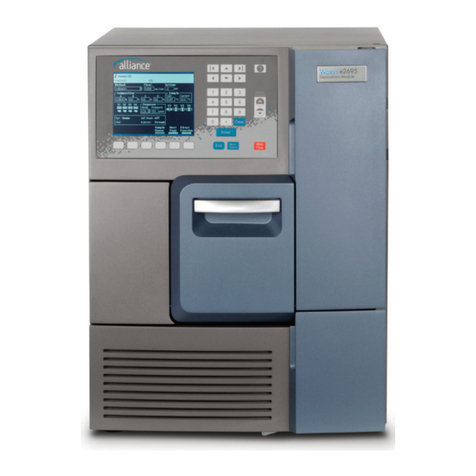
Waters Alliance e2695 Manual

Waters Alliance e2695
Separations Module
Operator’s Guide
715003794
Revision C
Copyright © Waters Corporation 2018
All rights reserved.

February 27, 2018, 715003794 Rev. C
Page ii

February 27, 2018, 715003794 Rev. C
Page iii
General Information
Copyright notice
© 2008 – 2018 WATERS CORPORATION. PRINTED IN THE UNITED STATES OF AMERICA
AND IN IRELAND. ALL RIGHTS RESERVED. THIS DOCUMENT OR PARTS THEREOF MAY
NOT BE REPRODUCED IN ANY FORM WITHOUT THE WRITTEN PERMISSION OF THE
PUBLISHER.
The information in this document is subject to change without notice and should not be construed
as a commitment by Waters Corporation. Waters Corporation assumes no responsibility for any
errors that may appear in this document. This document is believed to be complete and accurate
at the time of publication. In no event shall Waters Corporation be liable for incidental or
consequential damages in connection with, or arising from, its use. For the most recent revision of
this document, consult the Waters Web site (www.waters.com).
Trademarks
Waters, “THE SCIENCE OF WHAT’S POSSIBLE.”, Alliance, Empower, and Waters Quality Parts
are registered trademarks of Waters Corporation, and LACE/E, PerformancePLUS, and SAT/IN
are trademarks of Waters Corporation.
Fluorinert is a registered trademark of Solvay S.A.
Fluoroloy is a registered trademark of Saint-Gobain S.A.
Fomblin is a registered trademark of Solvay S.A.
Galden is a registered trademark of Solvay S.A.
Tefzel is a registered trademark of E. I. du Pont de Nemours and Company or its affiliates.
SealTight is a trademark of Upchurch Scientific, Inc. (IDEX Corporation).
Teflon is a trademark of The Chemours Company.
Triton is a trademark of Sigma-Aldrich Corporation.
Other registered trademarks or trademarks are the sole property of their owners.

February 27, 2018, 715003794 Rev. C
Page iv
Customer comments
Waters’ Technical Communications organization invites you to report any errors that you
encounter in this document or to suggest ideas for otherwise improving it. Help us better
understand what you expect from our documentation so that we can continuously improve its
accuracy and usability.
We seriously consider every customer comment we receive. You can reach us at
Contacting Waters
Contact Waters with enhancement requests or technical questions regarding the use,
transportation, removal, or disposal of any Waters product. You can reach us via the Internet,
telephone, or conventional mail.
Safety considerations
Some reagents and samples used with Waters instruments and devices can pose chemical,
biological, or radiological hazards (or any combination thereof). You must know the potentially
hazardous effects of all substances you work with. Always follow Good Laboratory Practice, and
consult your organization’s standard operating procedures.
Safety hazard symbol notice
Documentation needs to be consulted in all cases where the symbol is used to find out the
nature of the potential hazard and any actions which have to be taken.
Waters contact information
Contacting medium Information
Internet The Waters Web site includes contact information for Waters
locations worldwide. Visit www.waters.com.
Telephone and fax From the USA or Canada, phone 800-252-4752, or
fax 508-872-1990.
For other locations worldwide, phone and fax numbers appear in
the Waters Web site.
Conventional mail Waters Corporation
Global Support Services
34 Maple Street
Milford, MA 01757
USA

February 27, 2018, 715003794 Rev. C
Page v
Considerations specific to the Waters Alliance e2695
Separations Module
Power cord replacement hazard
Solvent leakage hazard
The source exhaust system is designed to be robust and leak-tight. Waters recommends you
perform a hazard analysis, assuming a maximum leak into the laboratory atmosphere of 10% LC
eluate.
Flammable solvents hazard
When using flammable solvents, ensure that a stream of nitrogen continuously flushes the
instrument’s source, and the nitrogen supply pressure remains above 690 kPa (6.9 bar, 100 psi).
You must also install a gas-fail device that interrupts the solvent flowing from the LC system in the
event the supply of nitrogen fails.
Hand crush hazard
High temperature hazard
Warning: To avoid electric shock, use the SVT-type power cord in the United States and
HAR-type (or better) cord in Europe. The main power cord must be replaced only with one
of adequate rating. For information regarding what cord to use in other countries, contact
your local Waters distributor.
Warning:
• To confirm the integrity of the source exhaust system, renew the source O-rings at
intervals not exceeding one year.
• To avoid chemical degradation of the source O-rings, which can withstand
exposure only to certain solvents,determine whether any solvents you use that
are not listed are chemically compatible with the composition of the O-rings.
Warning: To prevent ignition of flammable solvent vapors in the enclosed space of a mass
spectrometer’s ion source, ensure that nitrogen flows continuously through the source. The
nitrogen supply pressure must not fall below 690 kPa (6.9 bar, 100 psi) during an analysis
requiring the use of flammable solvents. Also a gas-fail device must be installed, to interrupt
the flow of LC solvent should the nitrogen supply fail.
Warning: To avoid hazards associated with the reciprocating or rotating parts in the source,
keep hand clear of the regions marked with yellow and gray labels.
Warning: To avoid burn injuries, avoid touching the source enclosure when operating or
servicing the instrument.

February 27, 2018, 715003794 Rev. C
Page vi
High voltage hazard
Bottle placement prohibition
FCC radiation emissions notice
Changes or modifications not expressly approved by the party responsible for compliance, could
void the users authority to operate the equipment. This device complies with Part 15 of the FCC
Rules. Operation is subject to the following two conditions: (1) this device may not cause harmful
interference, and (2) this device must accept any interference received, including interference that
may cause undesired operation.
Electrical power safety notice
Do not position the instrument so that it is difficult to disconnect the power cord.
Equipment misuse notice
If equipment is used in a manner not specified by its manufacturer, protections against personal
injury inherent in the equipment’s design can be rendered ineffective.
Safety advisories
Consult Appendix A for a comprehensive list of warning advisories and notices.
Warning: To avoid electric shock, observe these precautions:
• Do not remove the mass spectrometer’s protective panels. The components they cover
are not user-serviceable.
• When the instrument is in Operate mode, avoid touching the areas marked with the high
voltage warning symbol. To touch external areas marked with the symbol, first put the
instrument in Standby mode.
Warning: To avoid injury from electrical shock or fire, and damage to the equipment, do not place
vessels containing liquid atop the workstation or ancillary equipment or otherwise expose those
units to dripping or splashing liquids.
Prohibited: Do not place vessels containing liquid—such as solvent bottles—atop the
workstation or ancillary equipment or otherwise expose those units to dripping or splashing
liquids.

February 27, 2018, 715003794 Rev. C
Page vii
Operating this instrument
When operating this instrument, follow standard quality-control (QC) procedures and the
guidelines presented in this section.
Applicable symbols
Symbol Definition
Manufacturer
Date of manufacture
Authorized representative of the European Community
Confirms that a manufactured product complies with all applicable
European Community directives
or
Australia EMC compliant
Confirms that a manufactured product complies with all applicable
United States and Canadian safety requirements
Consult instructions for use
Alternating current
Electrical and electronic equipment with this symbol may contain
hazardous substances and should not be disposed of as general
waste.
For compliance with the Waste Electrical and Electronic Equipment
Directive (WEEE) 2012/19/EU, contact Waters Corporation for the
correct disposal and recycling instructions.
Serial number
Part number catalog number
5()

February 27, 2018, 715003794 Rev. C
Page viii
Audience and purpose
This guide is intended for use by individuals who need to install, operate, maintain, or troubleshoot
the Waters Alliance e2695 Separations Module.
This guide sets forth procedures for unpacking, installing, using, maintaining, and troubleshooting
the Waters Alliance e2695 Separations Module. It also includes appendixes for specifications,
spare parts, and solvent considerations.
Intended use of the Waters Alliance e2695 Separations Module
Waters designed the Alliance e2695 Separations Module, an integrated solvent and sample
management platform, to facilitate all critical separations functions. The Waters Alliance e2695
Separations Module is for research use only and is not intended for use in diagnostic applications.
Calibrating
To calibrate LC systems, follow acceptable calibration methods using at least five standards to
generate a standard curve. The concentration range for standards must include the entire range of
QC samples, typical specimens, and atypical specimens.
When calibrating mass spectrometers, consult the calibration section of the operator’s guide for
the instrument you are calibrating. In cases where an overview and maintenance guide, not
operator’s guide, accompanies the instrument, consult the instrument’s online Help system for
calibration instructions.
Quality control
Routinely run three QC samples that represent subnormal, normal, and above-normal levels of a
compound. If sample trays are the same or very similar, vary the location of the QC samples in the
trays. Ensure that QC sample results fall within an acceptable range, and evaluate precision from
day to day and run to run. Data collected when QC samples are out of range might not be valid. Do
not report these data until you are certain that the instrument performs satisfactorily.
EMC considerations
Canada spectrum management emissions notice
This class A digital product apparatus complies with Canadian ICES-001.
Cet appareil numérique de la classe A est conforme à la norme NMB-001.
ISM Classification: ISM Group 1 Class A
This classification has been assigned in accordance with IEC CISPR 11 Industrial Scientific and
Medical (ISM) instrument requirements.
Group 1 products apply to intentionally generated and/or used conductively coupled
radio-frequency energy that is necessary for the internal functioning of the equipment.

February 27, 2018, 715003794 Rev. C
Page ix
Class A products are suitable for use in all establishments other than residential locations and
those directly connected to a low voltage power supply network supplying a building for domestic
purposes.
There may be potential difficulties in ensuring electromagnetic compatibility in other environments
due to conducted as well as radiated disturbances.
EC authorized representative
Waters Corporation
Stamford Avenue
Altrincham Road
Wilmslow SK9 4AX UK
Telephone: +44-161-946-2400
Fax: +44-161-946-2480
Contact: Quality manager

February 27, 2018, 715003794 Rev. C
Page x

February 27, 2018, 715003794 Rev. C
Page xi
General Information ............................................................................................... iii
Copyright notice ......................................................................................................................... iii
Trademarks ................................................................................................................................ iii
Customer comments .................................................................................................................. iv
Contacting Waters ..................................................................................................................... iv
Safety considerations ................................................................................................................ iv
Safety hazard symbol notice........................................................................................ iv
Considerations specific to the Waters Alliance e2695 Separations Module ................. v
FCC radiation emissions notice ................................................................................... vi
Electrical power safety notice ...................................................................................... vi
Equipment misuse notice............................................................................................. vi
Safety advisories ......................................................................................................... vi
Operating this instrument .......................................................................................................... vii
Applicable symbols ..................................................................................................... vii
Audience and purpose................................................................................................ viii
Intended use of the Waters Alliance e2695 Separations Module ............................... viii
Calibrating................................................................................................................... viii
Quality control............................................................................................................. viii
EMC considerations .................................................................................................................. viii
Canada spectrum management emissions notice...................................................... viii
ISM Classification: ISM Group 1 Class A ................................................................... viii
EC authorized representative .................................................................................................... ix
1 Getting started with the Alliance e2695 Separations Module ........................... 19
1.1 Separations module overview ................................................................................................... 19
1.1.1 HPLC system configurations ......................................................................................... 20
1.1.2 Solvent bottle tray kits.................................................................................................... 20
1.1.3 Control of chromatographic functions ............................................................................ 22
1.1.4 Spill protection ............................................................................................................... 22
1.1.5 Record-keeping functions .............................................................................................. 23
1.1.6 Power supply ................................................................................................................. 23
1.2 Solvent management system overview ..................................................................................... 23
1.2.1 Solvent blending ............................................................................................................ 24
1.2.2 Prime/vent valve ............................................................................................................ 24
1.2.3 Plunger seal wash system ............................................................................................. 24
1.2.4 Loss of prime protection ................................................................................................ 24
1.2.5 Preferred plunger stroke volume ................................................................................... 25
1.2.6 In-line vacuum degasser................................................................................................ 25
Table of Contents

February 27, 2018, 715003794 Rev. C
Page xii
1.3 Sample management system overview ..................................................................................... 26
1.3.1 Flow path ....................................................................................................................... 26
1.3.2 Normal flow.................................................................................................................... 27
1.3.3 Injection ......................................................................................................................... 27
1.3.4 Carousel configuration................................................................................................... 27
1.3.5 Vial presence ................................................................................................................. 28
1.3.6 Syringe assembly .......................................................................................................... 28
1.4 Operating configurations ........................................................................................................... 29
1.4.1 System Controller mode ................................................................................................ 29
1.4.2 No Interaction mode ...................................................................................................... 30
1.4.3 Remote Control mode.................................................................................................... 31
1.5 Options and accessories ........................................................................................................... 33
1.5.1 Column heater ............................................................................................................... 33
1.5.2 Column heater/cooler .................................................................................................... 33
1.5.3 Column pre-heater......................................................................................................... 33
1.5.4 Sample heater/cooler..................................................................................................... 33
1.5.5 Syringes......................................................................................................................... 33
1.5.6 Sample loops ................................................................................................................. 34
1.5.7 Column selection valve.................................................................................................. 34
2 Install the e2695 Separations Module ................................................................. 37
2.1 Installation overview .................................................................................................................. 37
2.2 Site requirements ...................................................................................................................... 38
2.3 Firmware and software requirements ........................................................................................ 39
2.4 Unpack the instrument ............................................................................................................... 39
2.5 External connections ................................................................................................................. 40
3 Prepare the e2695 Separations Module for Operation ...................................... 41
3.1 Power-on the separations module ............................................................................................. 41
3.1.1 Start-up diagnostic tests ................................................................................................ 41
3.1.2 The Main screen ............................................................................................................ 41
3.2 Operating overview ................................................................................................................... 42
3.2.1 Screen display overview ................................................................................................ 42
3.2.2 Use the keypad.............................................................................................................. 44
3.2.3 Enter values in parameter fields .................................................................................... 45

February 27, 2018, 715003794 Rev. C
Page xiii
3.3 Configure the separations module ............................................................................................. 47
3.3.1 Set configuration parameters......................................................................................... 47
3.3.2 Configure the operating mode ....................................................................................... 52
3.4 Prepare the solvent management system ................................................................................. 56
3.4.1 Prepare solvent reservoirs............................................................................................. 57
3.4.2 Degassing solvents........................................................................................................ 57
3.4.3 Prime the plunger seal wash pump ............................................................................... 58
3.4.4 Prime the solvent management system......................................................................... 58
3.5 Prepare the sample management system for operation ............................................................ 59
3.5.1 Purge the system........................................................................................................... 59
3.5.2 Prime the needle wash pump ........................................................................................ 60
3.5.3 Adjust the seal pack....................................................................................................... 61
3.5.4 Load carousels .............................................................................................................. 62
3.6 Prepare the separations module for operation .......................................................................... 62
3.6.1 Prepare a new or dry separations module for operation................................................ 63
3.6.2 Prepare an idle or powered-off separations module for operation................................. 63
3.6.3 Change from a buffered solvent to an organic solvent .................................................. 64
3.7 Power-off the separations module ............................................................................................. 64
3.7.1 Flush the flow path......................................................................................................... 64
3.7.2 Power-off the separations module ................................................................................. 65
4 Front Panel Control .............................................................................................. 67
4.1 Routine start-up ......................................................................................................................... 67
4.1.1 Reinitialize the system ................................................................................................... 67
4.2 Load sample vials ...................................................................................................................... 67
4.2.1 Remove the carousel..................................................................................................... 68
4.2.2 Load vials....................................................................................................................... 68
4.2.3 Load the carousel .......................................................................................................... 68
4.2.4 Add new sample vials during a run................................................................................ 68
4.3 Monitor your HPLC system ....................................................................................................... 69
4.4 Perform direct functions ............................................................................................................ 72
4.4.1 Dry prime the system..................................................................................................... 74
4.4.2 Run System Prep........................................................................................................... 75
4.4.3 Wet prime the system .................................................................................................... 76
4.4.4 Purge the 2410 and 410 reference cell.......................................................................... 78
4.4.5 Equilibrate the system ................................................................................................... 78
4.4.6 Condition the column ..................................................................................................... 78
4.4.7 Inject samples................................................................................................................ 79

February 27, 2018, 715003794 Rev. C
Page xiv
5 Automatic Runs .................................................................................................... 81
5.0.1 System Controller or No Interaction mode..................................................................... 81
5.0.2 Controlled by Empower software................................................................................... 81
5.0.3 Controlled by MassLynx software.................................................................................. 82
5.1 Perform automatic runs in a standalone mode .......................................................................... 82
5.1.1 Run a sample set........................................................................................................... 82
5.1.2 View sample sets........................................................................................................... 83
5.1.3 Perform a run from a sample template .......................................................................... 84
5.1.4 Modify a sample set during a run................................................................................... 85
5.1.5 Stop a run ...................................................................................................................... 86
5.2 Perform automatic runs under Empower software control ........................................................ 86
5.2.1 Considerations when performing runs controlled by Empower software....................... 87
5.3 Perform automatic runs under MassLynx control ...................................................................... 87
5.3.1 Perform an automatic run using MassLynx software ..................................................... 88
6 Create Methods, Sample Sets, and Sample Templates ..................................... 89
6.0.1 Separation methods....................................................................................................... 89
6.0.2 Sample sets ................................................................................................................... 89
6.0.3 Sample templates .......................................................................................................... 90
6.1 Create and edit separation methods ......................................................................................... 90
6.1.1 Create a separation method .......................................................................................... 91
6.1.2 Edit a separation method............................................................................................... 92
6.1.3 Copy and edit a separation method............................................................................... 93
6.1.4 Lock and unlock a separation method ........................................................................... 93
6.2 Set separation method parameters ........................................................................................... 94
6.2.1 Set Mobile Phase screen parameter values .................................................................. 94
6.2.2 Set sample parameter values ...................................................................................... 100
6.2.3 Set autosampler parameter values.............................................................................. 101
6.2.4 Set column parameter values ...................................................................................... 103
6.2.5 Set I/O parameter values............................................................................................. 104
6.2.6 Set detector parameters .............................................................................................. 107
6.3 Create and edit a sample set .................................................................................................. 113
6.3.1 Link rows in a sample set ............................................................................................ 116
6.4 Create a sample template ....................................................................................................... 117

February 27, 2018, 715003794 Rev. C
Page xv
7 Maintenance Procedures .................................................................................... 119
7.1 Maintenance considerations .................................................................................................... 119
7.1.1 Proper operating procedures ....................................................................................... 119
7.1.2 Reinitialize the system ................................................................................................. 119
7.2 Spare parts .............................................................................................................................. 119
7.3 Troubleshooting with Connections INSIGHT ........................................................................... 119
7.4 Safety and handling ................................................................................................................. 120
7.5 Maintain the solvent management system .............................................................................. 121
7.5.1 Overview ..................................................................................................................... 121
7.5.2 Remove the head, seal wash assembly, and plunger ................................................ 123
7.5.3 Notes on replacing the plunger seals ......................................................................... 124
7.5.4 Replace the seal wash assembly seals ....................................................................... 126
7.5.5 Clean and replace the plunger .................................................................................... 128
7.5.6 Replace an inlet check valve cartridge ........................................................................ 129
7.5.7 Replace the in-line filter .............................................................................................. 131
7.6 Maintain the sample management system .............................................................................. 133
7.6.1 Remove side panel of separations module.................................................................. 135
7.6.2 Replace the lower needle wash frit (if so equipped) .................................................... 136
7.6.3 Replace the injector needle and seal pack .................................................................. 141
7.6.4 Clean the sample compartment................................................................................... 147
8 Diagnostic Testing and Troubleshooting ......................................................... 149
8.0.1 Proper operation .......................................................................................................... 149
8.1 Safety and handling ................................................................................................................. 149
8.2 Use the error log ..................................................................................................................... 150
8.3 Perform main diagnostic tests ................................................................................................. 150
8.3.1 Exit the Diagnostics screens........................................................................................ 151
8.3.2 Prime the plunger seal wash pump ............................................................................. 152
8.3.3 Perform the compression check ................................................................................. 152
8.3.4 Prime the needle wash pump ..................................................................................... 154
8.3.5 Adjust the seals ........................................................................................................... 154
8.3.6 Service utilities diagnostic tests ................................................................................... 156
8.4 Perform other diagnostic tests and functions .......................................................................... 156
8.4.1 Perform the motors and valves diagnostic test............................................................ 157
8.4.2 Sensors diagnostic function......................................................................................... 159
8.4.3 Static leak test ............................................................................................................. 161
8.4.4 Valve leak test.............................................................................................................. 162
8.4.5 Head removal and replacement function .................................................................... 163

February 27, 2018, 715003794 Rev. C
Page xvi
8.4.6 Inputs and outputs test ................................................................................................ 164
8.4.7 Keypad test ................................................................................................................. 165
8.4.8 Display test .................................................................................................................. 165
8.4.9 Carousel test ............................................................................................................... 165
8.4.10 Sample heater/cooler test ......................................................................................... 166
8.4.11 Defrost sample heater/cooler function ...................................................................... 166
8.4.12 Column heater or column heater/cooler test ............................................................. 167
8.4.13 Rebuild injector valves function ................................................................................. 168
8.4.14 Create a GPV Test Method........................................................................................ 168
8.4.15 Verify the firmware checksum.................................................................................... 168
8.5 Troubleshoot ............................................................................................................................ 169
8.5.1 General troubleshooting hints...................................................................................... 169
8.5.2 When to call Waters Technical Service ....................................................................... 170
8.5.3 Troubleshoot chromatography problems .................................................................... 171
8.5.4 Troubleshooting hardware problems .......................................................................... 175
A Safety Advisories ............................................................................................... 181
A.1 Warning symbols ..................................................................................................................... 181
A.1.1 Specific warnings......................................................................................................... 182
A.2 Notices .................................................................................................................................... 183
A.3 Bottles Prohibited symbol ....................................................................................................... 183
A.4 Required protection ................................................................................................................. 184
A.5 Warnings that apply to all Waters instruments and devices .................................................... 184
A.6 Warnings that address the replacing of fuses ......................................................................... 187
A.7 Electrical and handling symbols .............................................................................................. 189
A.7.1 Electrical symbols........................................................................................................ 189
A.7.2 Handling symbols ........................................................................................................ 190
B External Connections ........................................................................................ 191
B.1 Connect to the electrical power supply ................................................................................... 191
B.2 Connect tubing and attachments ............................................................................................ 193
B.2.1 Install the B-series drip tray......................................................................................... 193
B.2.2 Install A- and C-series drip tray and support bracket .................................................. 195
B.2.3 Install solvent supply tubing ........................................................................................ 199
B.2.4 Make waste line connections ...................................................................................... 200
B.2.5 Install needle wash and plunger seal wash reservoirs ................................................ 201
B.2.6 Connect the column .................................................................................................... 202

February 27, 2018, 715003794 Rev. C
Page xvii
B.2.7 Connect the column selection valve............................................................................ 203
B.2.8 Connect the detector ................................................................................................... 206
B.3 Signal connections .................................................................................................................. 207
B.3.1 I/O signal connections ................................................................................................. 208
B.3.2 Digital signal connections............................................................................................ 211
B.4 Add hardware options ............................................................................................................. 213
B.4.1 Install an optional sample loop .................................................................................... 214
B.4.2 Install the column heater and column heater/cooler.................................................... 216
B.4.3 Install a syringe ........................................................................................................... 216
C Specifications ..................................................................................................... 217
C.1 Physical specifications ............................................................................................................ 217
C.2 Environmental specifications .................................................................................................. 218
C.3 Electrical specifications ........................................................................................................... 218
C.4 Solvent management specifications ....................................................................................... 220
C.5 Sample management specifications ....................................................................................... 221
D Solvent Considerations ..................................................................................... 223
D.1 Introduction ............................................................................................................................. 223
D.1.1 Clean solvents............................................................................................................. 223
D.1.2 Solvent quality............................................................................................................. 223
D.1.3 Solvent reservoirs ....................................................................................................... 223
D.1.4 Preparation checklist................................................................................................... 224
D.1.5 Water........................................................................................................................... 224
D.1.6 Buffers......................................................................................................................... 224
D.1.7 Tetrahydrofuran (THF)................................................................................................. 224
D.1.8 GPC solvents and seal choices .................................................................................. 224
D.2 Solvent compatibility ............................................................................................................... 225
D.2.1 Solvents to avoid......................................................................................................... 225
D.2.2 Solvents to use............................................................................................................ 226
D.3 Solvent miscibility ................................................................................................................... 228
D.3.1 How to use miscibility numbers (M-numbers) ............................................................. 229
D.4 Buffered solvents .................................................................................................................... 230
D.5 Head height ............................................................................................................................ 230
D.6 Solvent viscosity ..................................................................................................................... 230

February 27, 2018, 715003794 Rev. C
Page xviii
D.7 Mobile phase solvent degassing ............................................................................................. 230
D.7.1 Gas solubility............................................................................................................... 231
D.7.2 Vacuum degassing...................................................................................................... 231
D.8 Wavelength selection .............................................................................................................. 232
D.8.1 UV cut-offs for common solvents ................................................................................ 232
D.8.2 Mixed mobile phases .................................................................................................. 233
D.8.3 Refractive indices of common solvents....................................................................... 234

February 27, 2018, 715003794 Rev. C
Page 19
1Getting started with the Alliance
e2695 Separations Module
1.1 Separations module overview
The Alliance e2695 Separations Module is an integrated solvent and sample management
platform. Integrating the two, traditional high performance liquid chromatography (HPLC)
components—a solvent management system and a sample management system—facilitates all
critical separations functions.
Figure 1–1: Alliance e2695 Separations Module (front view)
TP03527
Syringe
access door
Solvent
conditioning
tray access door
Solvent
delivery tray
access door
Sample
compartment
access door
Front panel
display and
keypad

February 27, 2018, 715003794 Rev. C
Page 20
1.1.1 HPLC system configurations
The separations module supports RS-232, IEEE-488, Ethernet, and I/O connections for
compatibility with a variety of HPLC system configurations. It can function in these ways:
• As the source of Input/Output and timing signals in a simple, standalone HPLC system
• As the IEEE-488 system controller in an HPLC standalone system that includes these
Waters detectors:
– 2414 or 2410* refractive index (RI), or 410* differential refractive index (dRI)
– 2414 RI, 2410 RI, or 410 dRI and the 2487* dual wavelength or 486* tunable
absorbance
– 2487 dual wavelength or 486 tunable absorbance
*A legacy product that is no longer available for purchase from Waters.
• As a component of an HPLC system controlled by Empower or MassLynx software that
uses IEEE-488 communications
• As a component of an HPLC system controlled by Empower software and that uses
Ethernet communications
• As a component of an HPLC system controlled by a non-Waters data system that uses
RS-232 communications
1.1.2 Solvent bottle tray kits
There are several solvent bottle tray kits available for use with Alliance HPLC system
configurations.
Table 1–1: Solvent bottle tray kit options
System configuration Kit part number Where used Description
A series:
Bottle organizer
176003103 Systems with a
separations module
only
Bottle tray comes with a
removable drip tray and is
stacked atop the detector.
Accommodates up to two
4-liter bottles and nine
1-liter bottles.
B series:
Bottle tray and
detector base
176003104 Systems with a
separations module
and a column heater or
column heater/cooler
installed
Bottle tray comes with a
removable drip tray and
adjacent detector base.
Enables placement of
detector atop column
heater. Accommodates up
to two 4-liter bottles and
four 1-liter bottles.
C series:
Bottle bucket
176003105 Any Alliance HPLC
system
Free-standing bottle tray.
Accommodates a
combination of 1 to 4-liter
bottles.
Other manuals for Alliance e2695
1
Table of contents
Other Waters Control Unit manuals
Popular Control Unit manuals by other brands

Mirion Technologies
Mirion Technologies Neutron Hp 10 user guide
Phoenix Contact
Phoenix Contact FL WLAN 1100 user manual
Ublox
Ublox ZED-F9K Integration manual
Econ
Econ Fig. 517 Installation & operation manual
General Photonics
General Photonics FPS-002 Instruction Notes
Helios
Helios AIR1-ULM Installation and operating instructions
