Waters Pump Control Module II User manual

Waters Pump Control
Module II
Installation Guide
71500078604/Revision B
Copyright © Waters Corporation 2009
All rights reserved

ii
Copyright notice
© 2009 WATERS CORPORATION. PRINTED IN THE UNITED STATES OF
AMERICA AND IRELAND. ALL RIGHTS RESERVED. THIS DOCUMENT
OR PARTS THEREOF MAY NOT BE REPRODUCED IN ANY FORM
WITHOUT THE WRITTEN PERMISSION OF THE PUBLISHER.
The information in this document is subject to change without notice and
should not be construed as a commitment by Waters Corporation. Waters
Corporation assumes no responsibility for any errors that may appear in this
document. This document is believed to be complete and accurate at the time
of publication. In no event shall Waters Corporation be liable for incidental or
consequential damages in connection with, or arising from, its use.
Trademarks
Millennium and Waters are registered trademarks of Waters Corporation,
and Empower, LAC/E, SAT/IN, and “THE SCIENCE OF WHAT’S
POSSIBLE.” are trademarks of Waters Corporation.
Other registered trademarks or trademarks are the sole property of their
owners.

iii
Customer comments
Waters’ Technical Communications department invites you to tell us of any
errors you encounter in this document or to suggest ideas for otherwise
improving it. Please help us better understand what you expect from our
documentation so that we can continuously improve its accuracy and
usability.
We seriously consider every customer comment we receive. You can reach us
at tech_comm@waters.com.

iv
Contacting Waters
Contact Waters®with enhancement requests or technical questions regarding
the use, transportation, removal, or disposal of any Waters product. You can
reach us via the Internet, telephone, or conventional mail.
Safety considerations
Some reagents and samples used with Waters instruments and devices can
pose chemical, biological, and radiological hazards. You must know the
potentially hazardous effects of all substances you work with. Always follow
Good Laboratory Practice, and consult your organization’s safety
representative for guidance.
When you develop methods, follow the “Protocol for the Adoption of Analytical
Methods in the Clinical Chemistry Laboratory,” American Journal of Medical
Technology, 44, 1, pages 30–37 (1978). This protocol addresses good operating
procedures and the techniques necessary to validate system and method
performance.
Waters contact information
Contacting medium Information
Internet The Waters Web site includes contact
information for Waters locations worldwide.
Visit www.waters.com, and click Waters
Division > Contact Waters Online.
Telephone and fax From the USA or Canada, phone 800
252-HPLC, or fax 508 872 1990.
For other locations worldwide, phone and fax
numbers appear in the Waters Web site.
Conventional mail Waters Corporation
34 Maple Street
Milford, MA 01757
USA

v
Safety advisories
Consult Appendix A for a comprehensive list of warning and caution
advisories.
Operating the Waters Pump Control Module II
When operating the Pump Control Module II, follow standard quality-control
(QC) procedures and the guidelines presented in this section.
Applicable symbols
Audience and purpose
This guide is intended for use by individuals whose familiarity with HPLC
ranges from novice to expert. It describes how to install the Pump Control
Module II in a multi-pump gradient system with up to three pumps controlled
by a Waters data control system.
Intended use of the Pump Control Module II
Waters designed the Pump Control Module II to provide programmable
control through a Waters data system of up to three, 500-series high-pressure
pumps.
Calibrating
To calibrate LC systems, follow acceptable calibration methods using at least
five standards to generate a standard curve. The concentration range for
standards should include the entire range of QC samples, typical specimens,
and atypical specimens.
Symbol Definition
Confirms that a manufactured product complies
with all applicable European Community
directives
Australia C-Tick EMC Compliant
ABN 49 065 444 751

vi
To calibrate mass spectrometers, consult the calibration section for the
operator’s guide of the instrument you are calibrating.
Quality-control
Routinely run three QC samples that represent subnormal, normal, and
above-normal levels of a compound. Ensure that QC sample results fall within
an acceptable range, and evaluate precision from day to day and run to run.
Data collected when QC samples are out of range might not be valid. Do not
report these data until you are certain that the instrument performs
satisfactorily.
ISM classification
ISM Classification: ISM Group 1 Class B
This classification has been assigned in accordance with CISPR 11 Industrial
Scientific and Medical, (ISM) instruments requirements. Group 1 products
apply to intentionally generated and/or used conductively coupled
radio-frequency energy that is necessary for the internal functioning of the
equipment. Class B products are suitable for use in both commercial and
residential locations and can be directly connected to a low voltage,
power-supply network.

Table of Contents 1
Copyright notice ................................................................................................... ii
Trademarks ............................................................................................................ ii
Customer comments ............................................................................................ iii
Contacting Waters ............................................................................................... iv
Safety considerations .......................................................................................... iv
Safety advisories.................................................................................................. v
Operating the Waters Pump Control Module II ......................................... i-v
Applicable symbols .............................................................................................. v
Audience and purpose.......................................................................................... v
Intended use of the Pump Control Module II..................................................... v
Calibrating ........................................................................................................... v
Quality-control.................................................................................................... vi
ISM classification .............................................................................................. i-vi
ISM Classification: ISM Group 1 Class B ......................................................... vi
1 Overview .................................................................................................. 1-1
Introduction ....................................................................................................... 1-2
System configurations ..................................................................................... 1-3
Ethernet configuration.................................................................................... 1-3
IEEE-488 configuration................................................................................... 1-4
Signal conditions .............................................................................................. 1-5
2 Installing the Pump Control Module II ............................................ 2-1
Selecting the site and unpacking .................................................................. 2-2
Selecting the site.............................................................................................. 2-2
Unpacking and inspecting the module ........................................................... 2-2
Rear-panel signal connections ....................................................................... 2-3
Ethernet signal cable connections .................................................................. 2-4
Table of Contents

2 Table of Contents
IEEE-488 signal cable connections................................................................. 2-5
Connecting the pumps..................................................................................... 2-7
Connecting the event cables............................................................................ 2-8
Powering-on the module ............................................................................... 2-12
Programming the module ............................................................................. 2-14
Maintenance and troubleshooting .............................................................. 2-14
Cleaning the cabinet...................................................................................... 2-14
Replacing the fuse.......................................................................................... 2-14
Troubleshooting ............................................................................................. 2-15
A Safety Advisories .................................................................................. A-1
Warning symbols ............................................................................................... A-2
Task-specific hazard warnings........................................................................ A-2
Warnings that apply to particular instruments, instrument components, and
sample types............................................................................................... A-3
Caution symbol .................................................................................................. A-5
Warnings that apply to all Waters instruments ......................................... A-5
Electrical and handling symbols ................................................................. A-12
Electrical symbols.......................................................................................... A-12
Handling symbols .......................................................................................... A-13
B Specifications ........................................................................................ B-1
Physical and environmental specifications ............................................... B-2
Accuracy and precision .................................................................................. B-2
Electrical specifications ................................................................................. B-3
Protection Class 1 ............................................................................................ B-3
Overvoltage Category II .................................................................................. B-3
Pollution Degree 2 ........................................................................................... B-3
Moisture protection – Normal (IPXO) ............................................................ B-3
AC-to-DC power specifications ..................................................................... B-4
C Spare Parts ............................................................................................ C-1

1-2 Overview
Introduction
The Waters®Pump Control Module II is an HPLC pump controller. Through
the medium of Waters data system software, it offers programmatic control of
high-pressure-mixing pumps in HPLC and MS systems.
Pump Control Module II
Depending on your pump configuration requirements, you can attach as many
as three Waters 510 or 515 HPLC Pumps to the module and regulate the
solvent composition and flow rates by programming instrument method
settings in Empower, Millennium, or MassLynx data control software. (For
the module’s firmware/software requirements, see the Waters Pump Control
Module II release notes.)
A single Waters 510 or 515 Pump in an HPLC system is ideal for
high-throughput isocratic analyses. When you control two or three of these
pumps through a data system and external controller, you can achieve
reproducible, multipump gradient delivery with exceptionally smooth
concurrent-stream blending.
TP02342

System configurations 1-3
System configurations
When the module is under data system control, it can operate in one of these
configurations:
• Where all system modules, including the Pump Control Module II,
communicate with the data system via an IEEE-488 bus interface
• Where all system modules, including the Pump Control Module II,
communicate with the data system via Ethernet communications
Restriction: You cannot use the module’s Ethernet port at the same time you
are using its IEEE-488 bus interface for communications.
Note: For details on the module’s software and firmware requirements, see
the Waters Pump Control Module II release notes.
Ethernet configuration
To communicate with the Waters data control system via Ethernet, an
Ethernet cable connects the module with the system’s Ethernet network in
one of two ways:
• Directly, through the Ethernet LAN card in the data control system
• Through a network switch
For more information, see “Ethernet signal cable connections” on page 2-4.

1-4 Overview
HPLC system configuration using Ethernet communications
IEEE-488 configuration
To communicate with the Waters data control system via IEEE-488, an
IEEE-488 cable connects the module to an IEEE-488 controller (a busLAC/E™
card in the data control system for Millennium32 or Empower software or an
NI IEEE-488 card for MassLynx software). For more information, see
“IEEE-488 signal cable connections” on page 2-5.
External event-in
(Inj or Stop Flow)
External event-out
(6 available)
Pump
APump
BPump
C
Ethernet
cable
Module-to-pump cable
Pump Control
Module II Event cables
Ethernet LAN card
Data control system

Signal conditions 1-5
HPLC system configuration using IEEE-488 communications
Signal conditions
Terminal strips for two event input (inject-start and stop-flow) and six event
output signal connections are located on the module’s rear panel (see
“Terminal strips” on page 2-8). All external event connections are relay
closures.
The event input signals the module to initiate a run or stop the flow using
event cables (see “Event-in connection” on page 2-10). The event outputs can
trigger external devices when programmed in the pump events table (see
“Event-out connections” on page 2-11).
The IEEE-488 communications interface on the module’s rear panel provides
the means to manually set the IEEE-488 addresses via switch settings (see
“IEEE-488 signal cable connections” on page 2-5).
Data control system
busLAC/E card
External event-in
(Inj or Stop Flow)
External event-out
(6 available)
Pump
APump
BPump
C
IEEE-488
cable
Module-to-pump cable
Pump Control
Module II Event cables

1-6 Overview

2-1
2Installing the Pump Control
Module II
Contents
Topic Page
Selecting the site and unpacking 2-2
Rear-panel signal connections 2-3
Powering-on the module 2-12
Programming the module 2-14
Maintenance and troubleshooting 2-14
Caution: To avoid damaging the module and voiding its warranty,
perform all procedures in the order specified in this guide before you
power-on the module (see “Powering-on the module” on page 2-12).

2-2 Installing the Pump Control Module II
Selecting the site and unpacking
Selecting the site
Follow these requirements:
• When communicating with the data control system via the IEEE-488
interface, install the module within reach of the system. A 2-M
IEEE-488 cable is supplied for this purpose.
Requirement: For IEEE-488 communications, the maximum allowable
distance between the pumps and the module is 2 meters.
• When communicating with the data control system via the Ethernet
interface, install the module within reach of the Ethernet LAN card or
network switch that connects to the system. A 3-M shielded Ethernet
cable is supplied.
• The module is approximately 14 cm wide by 41 cm deep by 20 cm high.
Allow at least 8 cm rear clearance for the cables.
• Operating temperature is 4 to 40 °C.
• Relative humidity is 10 to 90%, noncondensing.
• Vibration and shock are negligible.
• For power requirements, see Appendix B.
Unpacking and inspecting the module
Unpack the shipment, comparing all items received to those specified in the
packing list. Notify Waters immediately if you discover a discrepancy. In the
case of damages items, immediately notify the shipping agency and Waters
Technical Service.
Waters recommends you save the packing materials for future transport or
shipment.
Caution: Do not stack heavy devices or solvent containers atop the
module.
Warning: Always observe Good Laboratory Practices when handling
solvents and performing maintenance.

Rear-panel signal connections 2-3
Rear-panel signal connections
Use the signal connectors on the module’s rear panel to connect the module to
other HPLC system components. The following table summarizes these signal
connections.
The following figure shows the rear panel locations of the signal connectors
used to operate the module with external devices.
Component connector types
Connector type Component
Ethernet Waters data control system, such as an
Empower 2 system, connected via the
Ethernet network
Tip: The Ethernet port also supports the
Waters PC-based Autoloader utility for
installing firmware (for details, see the
Waters Pump Control Module II release
notes).
IEEE-488 Waters data control system, such as
Empower, Millennium32, or MassLynx
system connected via the IEEE-488 bus
Analog Event inputs/outputs
terminal strips Peripheral devices, such as column
select valves, column-switching valves,
and manual injectors
Pump (A, B, and C) Up to three, Waters 510 or 515 HPLC
Pumps
RS-232 For firmware upgrades only

2-4 Installing the Pump Control Module II
Rear panel of the Pump Control Module II
Ethernet signal cable connections
The module is equipped with a RJ-45 connector for Ethernet port
communications (see the figure, above). The Ethernet port—a 10/100 Base-T
networking interface—is used only for remote control, the case when
Empower 2 controls its operation, and for firmware upgrades via the Waters
Autoloader utility. Appendix C lists the supplied Ethernet cable.
Requirements:
• In an Ethernet configuration, all Waters HPLC system components,
including the module, must communicate with the data system via
Ethernet communications.
• As with IEEE-488 control, when using an autoinjector, triggering of the
inject-start signal occurs over the Ethernet cable, so no external I/O
cable is needed. For more information, see “Connecting the event cables”
on page 2-8.
RS-232
IEEE
488
PUMP A PUMP B
PUMP C
ETHERNET
!
V - 100-240
Hz 50-60
VA 60
F 3.15A / 250V
ETL LISTED
CONFORMS TO
UL STD 3101-1
CERTIFIED TO
CA/CSA C22.2 NO. 1010.1-92
IEEE
ADDRESS
16
8
4
2
1
10
Event input and
output
connectors
Pump
connectors
Fuse
Power
Ground stud
IEEE-488
address
IEEE-488
connector
RS-232
connector
Ethernet
connector

Rear-panel signal connections 2-5
Restriction: You cannot use the module’s Ethernet port at the same time you
are using its IEEE-488 bus interface for communications.
To make the Ethernet connections
1. Connect one end of the Ethernet cable to the Ethernet port on the
module’s rear panel (see the figure on page 2-4).
2. Connect the other end of the Ethernet cable to the Ethernet LAN
network card in the data control system or an Ethernet switch connected
to the data control system. For additional Ethernet configuration
information, see the Waters Ethernet Instrument Getting Started Guide
(P/N: 7150074403).
IEEE-488 signal cable connections
The IEEE-488 cable transmits digital data between the module and the
busLAC/E card. Observe the IEEE cabling and connection requirements, and
follow the IEEE specifications when adding the module to the existing
IEEE-488 connections. Appendix C lists the IEEE-488 cables.
Requirements:
• In an IEEE-488 configuration, all of the Waters HPLC system
components, including the module, must communicate with the data
system via IEEE-488 communications.
• When using an autoinjector, triggering of the inject-start signal occurs
over the IEEE-488 cable, so no external I/O cable is needed. For more
information, see “Connecting the event cables” on page 2-8.
Restriction: You cannot use the module’s Ethernet port at the same time you
are using its IEEE-488 bus interface for communications.
To make the IEEE-488 connections
1. Place the module on a level surface.
2. Insert one end of the IEEE-488 cable into the IEEE-488 port on the
module’s rear panel, and tighten both thumbscrews.
3. Insert and secure the other end of the cable to the IEEE-488 connection
on the busLAC/E card in the data control system.
Tip: You can daisy-chain IEEE-488 cables.

2-6 Installing the Pump Control Module II
Note: Each device on the IEEE communications bus requires a unique
IEEE-488 address. The module’s address must be a unique number from
2 to 29.
4. Set a unique IEEE-488 address on the module’s rear panel by moving
the appropriate switches from 0 to 1 (see the table on page 2-6 ).
Example: For an address of 7, add the numbers of the switches in the 1
position.
Setting the address switches
The following table shows the switch positions for addresses 2 to 29.
IEEE-488 switch settings
IEEE-488
address Switch settings
124816
2 0 1 0 0 0
3 1 1 0 0 0
4 0 0 1 0 0
5 1 0 1 0 0
6 0 1 1 0 0
7 1 1 1 0 0
8 0 0 0 1 0
9 1 0 0 1 0
10 01010
11 11010
12 00110
13 10110
IEEE
address
10
16
8
4
2
1
These settings have a
value of 0
Add 1 + 2 + 4 = 7
Table of contents
Other Waters Control Unit manuals
Popular Control Unit manuals by other brands
MEIG
MEIG SLM758 Hardware Design Guide
PA
PA VB 200 quick start guide

Pentair
Pentair E-Box INTELLIPOOL Installation and operation guide

Brainchild
Brainchild PR Series user guide
Pentair
Pentair HI FLOW SIX-WAY 1-1/2 INCH TOP MOUNT VALVE Installation and user guide
BENDIX
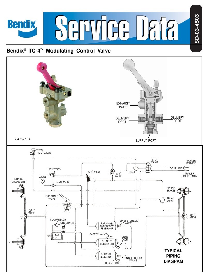
BENDIX TC-4 MODULATING CONTROL VALVE manual

