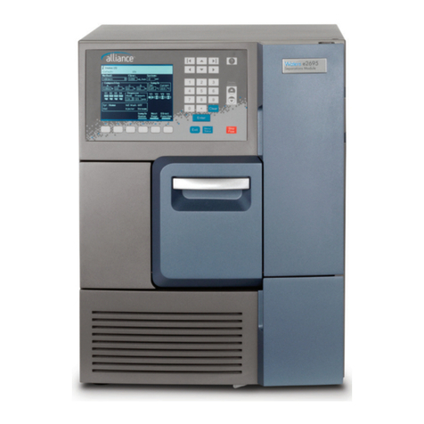
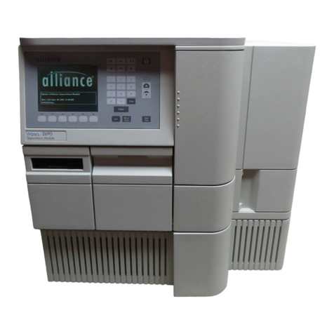
Waters 2545 Binary Gradient Module Manual

Waters 2545 Binary
Gradient Module
Operator’s Guide
71500134902 / Revision A
Copyright © Waters Corporation 2006
All rights reserved

ii
Copyright notice
© 2006 WATERS CORPORATION. PRINTED IN THE UNITED STATES OF
AMERICA AND IRELAND. ALL RIGHTS RESERVED. THIS DOCUMENT
OR PARTS THEREOF MAY NOT BE REPRODUCED IN ANY FORM
WITHOUT THE WRITTEN PERMISSION OF THE PUBLISHER.
The information in this document is subject to change without notice and
should not be construed as a commitment by Waters Corporation. Waters
Corporation assumes no responsibility for any errors that may appear in this
document. This document is believed to be complete and accurate at the time
of publication. In no event shall Waters Corporation be liable for incidental or
consequential damages in connection with, or arising from, its use.
Trademarks
Waters is a registered trademark, and AutoPurification, FractionLynx, and
MassLynx are trademarks of Waters Corporation.
Tefzel and Teflon are registered trademarks of E. I. du Pont de Nemours and
Company.
Other trademarks or registered trademarks are the sole property of their
respective owners.
Customer comments
Waters’ Technical Communications department invites you to tell us of any
errors you encounter in this document or to suggest ideas for otherwise
improving it. Please help us better understand what you expect from our
documentation so that we can continuously improve its accuracy and
usability.
We seriously consider every customer comment we receive. You can reach us
at tech_comm@waters.com.
Waters Corporation
34 Maple Street
Milford, MA 01757
USA

iii
Safety considerations
Some reagents and samples used with Waters instruments can pose chemical,
biological, or radiological hazards. Be sure you are aware of the potentially
hazardous effects of all substances you work with. Always follow Good
Laboratory Practice, and consult your organization’s safety representative for
guidance.
When you develop methods, follow the “Protocol for the Adoption of Analytical
Methods in the Clinical Chemistry Laboratory,” American Journal of Medical
Technology, 44, 1, pages 30–37 (1978). This protocol addresses good operating
procedures and the techniques necessary to validate system and method
performance.
Instrument-specific safety considerations
High voltage hazard
Safety advisories
Consult Appendix A for a comprehensive list of warning and caution
advisories.
Warning: To avoid electric shock, do not remove the 2545 Binary
Gradient Module’s protective panels. The components they cover
are not user-serviceable.

iv
Operating this device
When operating this device, follow standard quality control procedures and
the guidelines presented in this section.
Intended use
Waters®designed the 2545 Binary Gradient Module to manage solvents under
MassLynx™software control in Waters AutoPurification Systems.
Calibration
To calibrate HPLC systems, follow acceptable calibration methods using at
least five standards to generate a standard curve. The concentration range for
standards should cover the entire range of quality-control samples, typical
specimens, and atypical specimens.
To calibrate mass spectrometers, consult the calibration section of the
operator’s guide of the instrument you are calibrating.
Quality control
Routinely run three quality-control samples that represent subnormal,
normal, and above-normal levels of a compound. Ensure that quality-control
sample results fall within an acceptable range, and evaluate precision from
day to day and run to run. Data collected when quality control samples are out
of range might not be valid. Do not report these data until you are certain that
the instrument performs satisfactorily.
Warning: Although some of the modules in the AutoPurification
System might carry IVDD labels, the system as a whole is not
intended for clinical use.

Table of Contents v
Safety considerations ......................................................................................... iii
Operating this device ......................................................................................... iv
1 Setting up the 2545 Binary Gradient Module .................................. 1-1
Features .............................................................................................................. 1-2
Installing the binary gradient module ........................................................ 1-4
Unpacking and inspecting .............................................................................. 1-6
Making power connections ............................................................................. 1-7
Making plumbing connections ...................................................................... 1-9
Making signal connections ........................................................................... 1-16
2 Preparing for operation ....................................................................... 2-1
Powering on ....................................................................................................... 2-2
Scanning connected instruments .................................................................. 2-3
Configuring 515 pumps .................................................................................... 2-6
Creating the inlet method ............................................................................... 2-8
Defining the gradient ..................................................................................... 2-10
Entering timed events ................................................................................... 2-14
Setting up analog signals .............................................................................. 2-16
Preparing solvent reservoirs ....................................................................... 2-17
3 Maintenance ............................................................................................ 3-1
Maintenance considerations .......................................................................... 3-2
Removing the pump head and seal-wash assemblies ............................... 3-4
Replacing the seals and O-ring .................................................................... 3-10
Table of Contents

vi Table of Contents
Replacing the plunger .................................................................................. 3-16
Replacing an inlet check valve cartridge ................................................. 3-20
Replacing an outlet check valve cartridge ............................................... 3-22
Replacing the vent valve rotor-seal assembly .......................................... 3-24
Diagnostics and configuration .................................................................... 3-28
Performing the leak test ............................................................................... 3-29
4 Troubleshooting ..................................................................................... 4-1
System troubleshooting .................................................................................. 4-2
Alarm reset ......................................................................................................... 4-4
Error messages .................................................................................................. 4-5
Troubleshooting hardware ............................................................................. 4-8
A Safety Advisories .................................................................................. A-1
Warning symbols ............................................................................................... A-2
Caution symbol .................................................................................................. A-6
Warnings that apply to all Waters instruments ......................................... A-7
Electrical and handling symbols ................................................................. A-14
B Specifications ........................................................................................ B-1
Physical specifications ................................................................................... B-2
Environmental specifications ....................................................................... B-3
Electrical specifications ................................................................................. B-4
Solvent management system specifications .............................................. B-7
Index ..................................................................................................... Index-1

1-2 Setting up the 2545 Binary Gradient Module
Features
The Waters®2545 Binary Gradient Module is a high-flow, high-pressure
mixing binary-gradient pump that delivers solvent for the Waters
AutoPurification™ System.
Based on Waters high-performance solvent management technology, the
binary gradient module provides consistently smooth, pulse-free solvent flow
for both analytical and preparative flow rates. The binary gradient module is
capable of pumping four solvents. Only two solvents can be programmed for
any gradient.
Pump systems A and B
Each binary gradient module consists of two independent pump systems,
A (top) and B (bottom). Each independent pump system contains two
linear-drive actuators (left and right). Each left and right actuator pair
contributes equally (in parallel) to deliver precise flows of a single solvent.
A
B

Features 1-3
The two independent pump systems combine their two solvents at a filter/tee,
where the solvent mix is plumbed to the sample manager or another
component of the AutoPurification System.
MassLynx™ software controls the ratio of the two solvents by varying the
relative flows of pump A and pump B. The binary gradient module receives
pressure data from a pressure transducer associated with each pump head.
The firmware measures the individual pump head pressure during the
pumping cycle and adjusts the precompression to ensure consistent solvent
delivery and minimize pump-induced detector baseline disturbances.
The MassLynx interface with the binary gradient module also provides useful
diagnostics and troubleshooting routines.
Leak management
All fluid-handling areas of the binary gradient module contain leak routing
capability. Spilled solvent is routed to the drain tube below the front panel.
The optional leak sensor should be installed on the leak sensor bracket in the
drip tray.
See also: Waters AutoPurification System Guide and Waters System Fluidics
Organizer Operator’s Guide.

1-4 Setting up the 2545 Binary Gradient Module
Installing the binary gradient module
To install the binary gradient module, you should know how to set up and
operate general laboratory instruments and computer-controlled devices, and
how to handle solvents.
See also: Contacting Waters Technical Service on page 3-2.
Required materials
• Flat-blade screwdriver (included in Startup Kit)
• 1/2-inch open-end wrench (included in Startup Kit)
• 5/16-inch open-end wrench (included in Startup Kit)
Site requirements
Factor Requirement
Internal cooling DC-powered fans that provide internal cooling by
pulling air through the binary gradient module
and exhausting it out the rear of the unit.
Airflow requirements Air enters the front of the binary gradient module
so pumps and other instrumentation can be placed
side by side.
Clearance At least 6 inches (15 cm) between the rear of the
binary gradient module and the wall to allow for
electrical connections and the ventilation fans’
exhaust.
Operating temperature 4 to 40 °C (39.2 to 104 °F)
Humidity 20% to 80%, noncondensing
Instrument-generated
acoustic noise <60 dBA at idle
Height 17 inches (43 cm)
Width 11 inches (28 cm)
Depth 31 inches (79 cm) with cables connected at the
rear; includes heads and tubes at the front
Weight 125 pounds (57 kg)
Line voltage 100 to 240 Vac ±10 V

Installing the binary gradient module 1-5
Frequency 50/60 Hz
Current requirements,
fusing 10 A, 5 ×20 mm, slow-blow, IEC type
Power consumption 650 W
Warning: System configurations are designed to meet safety and
performance standards. All systems must adhere to a model in which any one
“base” Waters module (i.e., the System Fluidics Organizer, the 2545 Binary
Gradient Module, or the 3100 Mass Detector) supports no more than two
vertically oriented “accessory” Waters modules (e.g., 515 pumps, photodiode
array detectors, evaporative light scattering detectors, or dual wavelength
absorbance detectors). Configuring modules in such a way that fails to meet
said design is neither recommended nor supported by Waters Corporation.
When configurations require module stacking outside the noted parameters,
the customer assumes liability.
Site requirements (Continued)
Factor Requirement

1-6 Setting up the 2545 Binary Gradient Module
Unpacking and inspecting
The binary gradient module is shipped in a single carton on a wooden pallet.
Save the carton and pallet in case you transport or ship the unit later.
To unpack and inspect the binary gradient module:
1. Ensure that there is sufficient bench space for the binary gradient
module.
2. Check the outside of the shipping carton for signs of damage. Document
or photograph areas of damage.
3. Remove the plastic wrap, if any, and the bands securing the carton to
the pallet. Remove the top and the sides of the shipping carton, the
Startup Kit, and the packing material.
4. Check that the contents of the Startup Kit match the Startup Kit list.
5. Remove the binary gradient module from the bottom styrofoam cushion
and the box bottom, and place it on a level, clean surface, making sure to
leave room for the other system components.
6. Check that the instrument serial number (found on the rear panel near
the power cord connector) corresponds to the number on the Certificate
of Validation.
7. If you detect any damage to the contents of the carton, refer to
Shipments, Damages, Claims, and Returns, in Waters Licenses,
Warranties, and Support Services.
8. Measure the voltage at the receptacle, and verify that the voltage is
between 90 and 264 Vac.
Caution: To prevent damage, lift the module by the bottom sides of
the unit.
Warning: To avoid injury, ensure that at least two people lift the
module from the pallet to the bench. Most of the module’s weight is
at the front.
!

Making power connections 1-7
Making power connections
Requirements: Make sure the AC power supply is grounded and has no
abrupt voltage fluctuations.
The binary gradient module automatically adjusts for AC input voltages of
100 to 240 V, 50/60 Hz.
To connect the binary gradient module to the power source:
1. Ensure that the power switch on the front of the binary gradient module
is in the Off position.
2. Connect the female end of the power cord to the power entry module on
the rear of the binary gradient module.
Caution: Do not power on the binary gradient module until you
have completed all plumbing and signal connections.
Warning: To avoid electrical shock and possible injury, remove the
power cord from the rear panel of the instrument before you
perform this procedure.
!

1-8 Setting up the 2545 Binary Gradient Module
Rear panel of 2545 Binary Gradient Module
3. Insert the other end of the power cord into a grounded power receptacle.
Key
Number Name
1Power entry module
2Fuse holder
3Ethernet RJ45 port
4Connector A
5Connector B
3
4
5
2
1

Making plumbing connections 1-9
Making plumbing connections
Installing solvent inlet tubes
Required materials
• Solvent inlet tubes assembly (part number 430000573)
• 1/2-inch wrench
Recommendation: Perform a dry prime before making the initial plumbing
connections (see page 2-18).
To make the initial plumbing connections:
1. Using a 1/2-inch wrench, loosen the solvent inlet fitting on the manifold.
2. Slide the nut and ferrule retainer, followed by the ferrule (small end
toward the end of the tube) onto the solvent tube.
3. Press the tube all the way into the fitting and tighten the nut using the
1/2-inch wrench. Tighten the fitting 3/4 of a turn beyond finger tight.
4. Repeat steps 1 to 3 for the remaining solvent tubes.
Caution: Check all fittings and tighten if necessary. The fittings
can loosen during shipment, particularly if the module has
undergone temperature extremes.
!

1-10 Setting up the 2545 Binary Gradient Module
Plumbing connections for seal wash
Key
Number Name
1Seal-wash pump A
2Seal-wash A inlet tube
15
12
3
2
1
10
13
11
8
4
9
14
5
67
12
12

Making plumbing connections 1-11
If you plan to run only two solvents, make sure to plumb one solvent into
each manifold and connect the tube to a port in each manifold.
You can shorten the solvent inlet tubes to accommodate the solvent
container locations.
5. Insert the filter ends of the solvent tubes into the appropriate solvent
container.
3Filter
4Seal-wash B outlet tube
5Drip tray
6Drain tube
7Inlet manifold B
8Seal-wash B connection tube
9Seal-wash B inlet tube
10 Vent valve
11 Seal-wash pump B
12 Waste outlet at tee fitting
13 Seal-wash A outlet tube
14 Seal-wash A connection tube
15 Inlet manifold A
Caution: The binary gradient module does not require pressurized
solvent containers for reliable operation. If using pressurized
containers for blanketing large containers of solvent, do not exceed
5 psig. Pressures above 5 psi can force solvent through the internal
components of the solvent selection valve (SSV), possibly causing a
spillover into the solvent waste reservoir or an adverse mixture
with other solvents.
Key (Continued)
Number Name
!

1-12 Setting up the 2545 Binary Gradient Module
Installing seal-wash solvent supply tubes
Each seal-wash solvent supply tube is pre-assembled with a free-sliding
PEEK compression screw, stainless steel collar, and yellow ferrule. Be careful
not to lose these parts when working with these tubes.
Required material
Seal-wash inlet tube assembly (part number 430000576)
To install the seal-wash solvent supply tubes:
1. Insert the seal-wash solvent supply tube into the top port of the pump A
seal-wash pump. Ensure the tube is pressed into the pump before
tightening the compression screw to set the ferrule.
Caution: Do not re-use the solvent inlet tube ferrule more than two
times. Re-use may result in slow leaks. Cut the end of the tube
squarely and use a new ferrule. The nut can be re-used.
Warning: To avoid possible harmful vapors, position solvent
containers in a safe place, such as in a fume hood or under a
counter vented to the outside.
!

Making plumbing connections 1-13
Installing the seal-wash solvent supply tubes
2. Install a second tube to the pump B seal-wash pump.
Installing the seal-wash waste tube
Required material
Seal-wash waste tube assembly (part number 430000575)
To install the seal-wash waste tube:
1. Remove the black cap from the end of the tube and install the tube into
the seal-wash outlet port on the right side of the right pump A head.
Caution: To properly drain the waste fluid, ensure that the waste
tube has no crimps or bends. A crimped or bent drain tube may
prevent adequate flow to the waste container.
!

1-14 Setting up the 2545 Binary Gradient Module
Installing the seal-wash waste tube
2. Repeat step 1, but install the compression screw into the left side of the
left pump B head.
Installing the vent valve waste tube
Required materials
• Waste tube assembly (part number 430000574)
• 5/16-inch open-end wrench
To install the vent valve waste tube:
1. Install the waste tube to the waste outlet at the T-fitting (to the right of
the vent valve).
2. Install the free end of the tube in the waste container.
Installing the drip tray
The drip tray is mounted at the bottom of the binary gradient module bezel.
The optional leak sensor should be installed on the leak sensor bracket in the
drip tray.
See also: Waters AutoPurification System Guide.
Caution: To properly drain the waste fluid, be sure to secure the
end of the waste tube in the waste container.
!
Table of contents
Other Waters Control Unit manuals
Popular Control Unit manuals by other brands

ABB
ABB ACS 600 MultiDrive user manual
GEA
GEA VARIVENT T R Series operating instructions
Hydro Instruments
Hydro Instruments PRV-71H Series Operation and maintenance manual

Honeywell
Honeywell RM7800L1087 installation instructions

Chamberlain
Chamberlain LiftMaster Professional Security+ 395LM Owner's instructions
Inel
Inel CRS-435XG Operation and installation manual, Safety notes


