Waters WAT051518 User manual

December 11, 2015, WAT051512 Rev. B
Page 1
Waters Gradient Mixer
The Waters®Gradient Mixer (kit part number WAT051518) is a stainless steel mixing
chamber for multi-component mobile phase applications where the gradient is
generated within the system and a homogeneous solvent blend is critical. The module
blends solvents from either separate gradient or on-line isocratic solvent delivery
systems at flow rates between 1.0 and 9.9 milliliters per minute. The mixer provides
significant chromatographic improvement in compositional consistency, resulting in
reduced baseline noise at high detector sensitivity.
Note: For safety advisory information, see the Safety Appendix in the associated
operator’s guide.
Introduction
Generally, the greater the imbalance between the solvents used to make up the
mobile phase, the more mixing volume is required. The Gradient Mixer enhances
mixing through a series of cascaded low-volume mixing chambers. The chambers,
connected by 0.005-inch channels, cause linear velocity to increase as solvent flows
through them. Wetted surfaces are 316 stainless steel and TFE Teflon seals. The
Gradient Mixer is compatible with any backpressure within the normal operating range
of standard Waters solvent delivery systems.
Contents:
Topic Page
Introduction ................................................................................................ 1
Required materials....................................................................................... 2
Operating the gradient mixer......................................................................... 3
Maintaining the gradient mixer ...................................................................... 4
Waters and “THE SCIENCE OF WHAT’S POSSIBLE.” are
registered trademarks of Waters Corporation.
All other trademarks are the sole property of their respective owners.
Copyright © 1991−2015 Waters Corporation.
*WAT051512* *Rev.B*

December 11, 2015, WAT051512 Rev. B
Page 2
Required materials
From the Waters Gradient Mixer kit, part number WAT051518:
Installing the gradient mixer
To install the gradient mixer:
1. Position the gradient mixer on the bench top to allow easy visual leak detection.
2. Connect the gradient mixer as shown in Figure 1:1 “Gradient mixer
connections”.
Note: If you are using 3 pumps, add another tee fitting (not included in the kit)
as shown in the inset.
Figure 1–1: Gradient mixer connections
3. Be sure to use an in-line filter (part number WAT035190 included in the kit)
since particles in the solvent can clog the 0.005-inch passages inside the
gradient mixer.
Note: If you are operating a ternary pumping system, a second tee fitting (part
number WAT075215) is required which is not supplied in the mixer kit.
Table 1–1: Gradient mixer kit materials description
Description Waters part number Quantity
Gradient mixer WAT051519 1
In-line filter (2 micron) WAT035190 1
Replacement filter element WAT088084 1
Jumper tube WAT038148 1
Compression screw WAT025313 2
Ferrule WAT022330 2
Tee fitting WAT075215 1
December 11, 2015, WAT051512 Rev. B
Page 3
Follow the next procedure if tubing cutting is required to connect the gradient mixer.
To trim the tubing:
1. Using a file with a cutting edge, (such as the file included in the startup tool kit,
part number WAT096146, supplied with each Waters LC System) scribe the
circumference of the tubing at the desired break.
2. Grasp the tubing on both sides of the scribe mark with cloth-covered pliers (to
prevent marring the tube surface) and gently work the tube back and forth until
it separates.
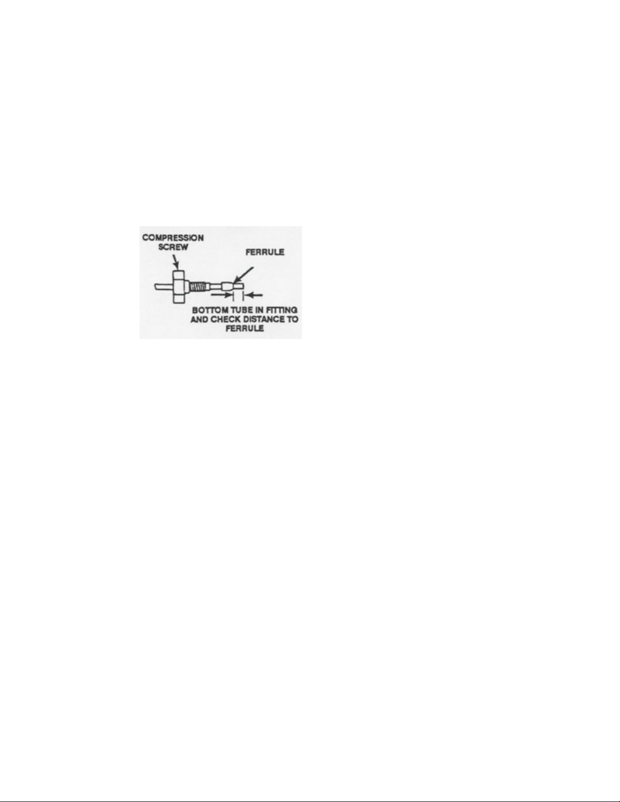
Figure 1–2: Compression screw and ferrule assembly
3. Slide the compression fitting, followed by the ferrule (large end of the taper
first) over the tube. Bottom the tube in the fitting seat where it will actually be
attached to assure a leak-free connection.
4. Tighten the screw 3/4-turn from finger tight.
Note: Before running your sample, flush the gradient mixer thoroughly with
selected mobile phase.
Operating the gradient mixer
Assess your system volume variables. For example, leaving a manual injector in the
"inject" position can increase volume by as much as 2 3 mL. Such practices contribute
significantly to solvent changeover time.
Starting up
Flush the Gradient Mixer with at least 10 mL of fresh mobile phase when starting up
your LC system after a brief shutdown (overnight).
Note: Making a mobile phase changeover also requires flushing the gradient mixer
with at least 10 mL of new mobile phase. However, if the new mobile phase is
immiscible with the old one, flush with 10-15 mL of an intermediate polarity mobile
phase before changing over.
Shutting down
For overnight shut down, be sure to flush salt buffers from the gradient mixer with
water.

December 11, 2015, WAT051512 Rev. B
Page 4
If the gradient mixer is left attached to the LC system during prolonged shutdowns,
thoroughly flush any halogenated mobile phases and/or aqueous mobile phase
(especially salt buffers) from the gradient mixer and store the gradient mixer in an
organic solvent, such as 100% methanol.
If the gradient mixer is removed from the system and stored, follow the steps
outlined above for prolonged storage then displace all solvent within the unit with an
inert gas (nitrogen flush).
Maintaining the gradient mixer
The gradient mixer requires a minimum of maintenance. Follow these procedures to
ensure maximum efficiency.
To maintain the gradient mixer:
1. Be sure to follow the proper start up and shut down procedures outlined in
“Operating the gradient mixer”.
2. Check your operating backpressure regularly for increases above normal. This is
often caused by a clogged in-line filter and is easily verified by removing the
column and checking the pressure drop across the in-line filter alone. If the
pressure drop is high, replace the filter inside the assembly as follows:
a. Unscrew the two halves of the in-line filter assembly (plumbed before the
gradient mixer as shown in Figure 1:1 “Gradient mixer connections”) and
remove the filter.
b. Place a new filter in the assembly and hand tighten.
Note: If the gradient mixer is the cause of the increase, change the direction of
flow. This should dislodge any foreign matter within the narrow passageways
and correct the pressure problem.
Waters limited product warranty
Waters corporation provides this limited warranty (the Warranty) to protect customers
from nonconformity in the product workmanship or materials. The warranty covers all
new products manufactured by Waters and its subsidiaries.
The warranty is as follows:
Waters warrants that all products sold by them will be of good quality and
workmanship. The products will be fit for their intended purpose(s) when used strictly
in accordance with Waters instructions for use during the applicable warranty period.
Table 1–2: Replacement parts
Description Part number Quantity
Compression screws WAT025313 2
Ferrules WAT022330 2
In-line filter element WAT088084 1
Tee fitting WAT075215 1

December 11, 2015, WAT051512 Rev. B
Page 5
The foregoing warranty is exclusive and in lieu of all other express and implied
warranties, including but not limited to fitness for any other purpose(s). In no event
will Waters be liable for consequential, economic or incidental damages of any nature.
Waters reserves the right not to honor this warranty if the products are abused by the
customer. The Warranty will not be deemed to have failed of its essential purpose so
long as Waters is able and willing to repair or replace any non-conforming part or
product.
Warranty service
Warranty service will be performed at no charge and at Waters option in one of three
ways: (1) a service representative will be dispatched to the customer's facility; (2)
the product will be repaired at a Waters repair facility; or (3) replacement parts with
appropriate installation instructions will be sent to the customer.
Non-conforming products or parts will be repaired, replaced with new or like-new
parts, or refunded in the amount of the purchase price, when the product is returned.
Warranty service will be performed only if the customer notifies Waters within 30 days
of discovering any non-conformity.
Unless otherwise agreed at the time of sale, warranty service will not be provided by
dispatching a service representative when the equipment has been removed from the
initial installation location to a new location outside the home country of the selling
company.
Warranty service will not be performed upon:
• Any product or part which has been repaired by others, improperly installed,
altered, or damaged in any way.
• Product or parts identified prior to sales as not manufactured by Waters. In such
cases, the warranty of the original manufacturer will apply.
• Products that malfunction because the customer has failed to perform
maintenance, calibration checks, or observe good operating procedures.
Repair or replacement will not be made:
• For expendable items such as filament devices, panel lights, fuses, batteries,
and seals, if such items were operable at the time of initial use.
• Because of decomposition due to chemical action.
• For used equipment.
• Because of poor facility, operating conditions or utilities.
Table of contents


