Waters ACQUITY UPLC I-Class Series Parts list manual

ACQUITY UPLC I-Class Series
System Guide
715005704
Revision A
Copyright © Waters Corporation 2018
All rights reserved

General information
Copyright notice
© 2018 WATERS CORPORATION. PRINTED IN THE UNITED STATES OF AMERICA AND IN
IRELAND. ALL RIGHTS RESERVED. THIS DOCUMENT OR PARTS THEREOF MAY NOT BE
REPRODUCED IN ANY FORM WITHOUT THE WRITTEN PERMISSION OF THE PUBLISHER.
The information in this document is subject to change without notice and should not be construed
as a commitment by Waters Corporation. Waters Corporation assumes no responsibility for any
errors that may appear in this document. This document is believed to be complete and accurate
at the time of publication. In no event shall Waters Corporation be liable for incidental or
consequential damages in connection with, or arising from, its use. For the most recent revision
of this document, consult the Waters website (waters.com).
Trademarks
ACQUITY® is a registered trademark of Waters Corporation.
ACQUITY UPLC® is a registered trademark of Waters Corporation.
Analyst® is a registered trademark of Applied Biosystems/MDS Analytical Technologies.
Auto•Blend PlusTM is a trademark of Waters Corporation.
Connections INSIGHT® is a registered trademark of Waters Corporation.
eCordTM is a trademark of Waters Corporation.
Empower® is a registered trademark of Waters Corporation.
KEL-F® is a registered trademark of 3M.
Keps® is a registered trademark of Illinois Tool Works Inc.
LAC/ETM is a trademark of Waters Corporation.
MassLynx® is a registered trademark of Waters Corporation.
Millennium® is a registered trademark of Waters Corporation.
MP35NTM is a trademark of SPS Technologies Inc.
PharMed® is a registered trademark of Saint-Gobain Performance Plastics Corporation.
PHILLIPS® is a registered trademark of Phillips Screw Company.
April 4, 2018, 715005704 Rev. A
Page ii

PEEKTM is a trademark of Victrex PLC.
PEEKsilTM is a trademark of SGE Analytical Science Pty Ltd.
PIC® is a registered trademark of Waters Corporation.
Teflon® is a registered trademark of E.I. du Pont de Nemours and Company or its affiliates.
THE SCIENCE OF WHAT'S POSSIBLE® is a registered trademark of Waters Corporation.
TORX® is a registered trademark of Acument Intellectual Properties, LLC in the United States or
other countries.
TritonTM X-100 is a trademark of The Dow Chemical Company or an affiliated company of Dow.
TWEENTM is a trademark of ICI Americas Inc.
Tygon® is a registered trademark of Saint-Gobain Performance Plastics Corporation.
UPLC® is a registered trademark of Waters Corporation.
XBridge® is a registered trademark of Waters Corporation.
Waters® is a registered trademark of Waters Corporation.
All other trademarks are property of their respective owners.
Customer comments
Waters’ Customer Experience and Knowledge Management organization invites you to report any
errors that you encounter in this document or to suggest ideas for otherwise improving it. Help us
better understand what you expect from our documentation so that we can continuously improve
its accuracy and usability.
We seriously consider every customer comment we receive. You can reach us at
Contacting Waters
Contact Waters with enhancement requests or technical questions regarding the use,
transportation, removal, or disposal of any Waters product. You can reach us via the Internet,
telephone, fax, or conventional mail.
April 4, 2018, 715005704 Rev. A
Page iii

Waters contact information
Contacting medium Information
Internet The Waters Web site includes contact information for Waters locations
worldwide.
Visit www.waters.com
Telephone and fax From the USA or Canada, phone 800-252-4752, or fax 508-872-1990.
For other locations worldwide, phone and fax numbers appear in the
Waters Web site.
Conventional mail Waters Corporation
Global Support Services
34 Maple Street
Milford, MA 01757
USA
Safety considerations
Some reagents and samples used with Waters instruments and devices can pose chemical,
biological, or radiological hazards (or any combination thereof). You must know the potentially
hazardous effects of all substances you work with. Always follow Good Laboratory Practice
(GLP), and consult your organization’s standard operating procedures as well as your local
requirements for safety.
System height
Warning: To avoid injury, do not stack modules, including the solvent tray and rails,
higher than one meter (39.4 inches) above the bench top.
Warning: To avoid spinal and muscular injury, do not attempt to lift a system module
without assistance.
Warning: To avoid crushing your fingers beneath or between modules, use extreme
care when installing a module in the system stack.
Safety hazard symbol notice
Documentation needs to be consulted in all cases where the symbol is used to find out the
nature of the potential hazard and any actions which have to be taken.
April 4, 2018, 715005704 Rev. A
Page iv

Power cord replacement hazard
Warning: To avoid electric shock, use SVT-type power cords in the United States and
HAR-type (or better) cords in Europe. The power cords must be replaced only with ones
of adequate rating. For information regarding which cord to use in other countries,
contact your local Waters distributor.
Hand crush hazard
Warning: To avoid hazards associated with the reciprocating or rotating parts in the
source, keep hands clear of the regions marked with yellow and gray labels.
High voltage hazard
Warning: To avoid electric shock, do not remove protective panels from system
modules. The components within are not user-serviceable.
Bottle placement prohibition
Warning: To avoid injury from electrical shock or fire, and damage to the equipment, follow
these guidelines:
• Do not expose the workstation or ancillary equipment to dripping or splashing liquids.
• Do not place objects filled with liquid, such as solvent bottles, on top of the workstation or
ancillary equipment.
FCC radiation emissions notice
Changes or modifications not expressly approved by the party responsible for compliance, could
void the user's authority to operate the equipment. This device complies with Part 15 of the FCC
Rules. Operation is subject to the following two conditions: (1) this device may not cause harmful
interference, and (2) this device must accept any interference received, including interference that
may cause undesired operation.
Electrical power safety notice
Do not position the device so that it is difficult to disconnect the power cord.
April 4, 2018, 715005704 Rev. A
Page v

Equipment misuse notice
If equipment is used in a manner not specified by its manufacturer, protections against personal
injury inherent in the equipment’s design can be rendered ineffective.
Safety advisories
Consult the "Safety advisories" appendix in this publication for a comprehensive list of warning
advisories and notices.
Operating the system
When operating the system, follow standard quality-control (QC) procedures and the guidelines
presented in this section.
Applicable symbols
The following symbols can be present on the device, system, or packaging.
Symbol Definition
Manufacturer
Date of manufacture
Authorized representative of the European Community
Confirms that a manufactured product complies with all applicable
European Community directives
or
Australia EMC compliant
Confirms that a manufactured product complies with all applicable United
States and Canadian safety requirements
Consult instructions for use
Alternating current
April 4, 2018, 715005704 Rev. A
Page vi

Symbol Definition
Electrical and electronic equipment with this symbol may contain
hazardous substances and should not be disposed of as general waste.
For compliance with the Waste Electrical and Electronic Equipment
Directive (WEEE) 2012/19/EU, contact Waters Corporation for the correct
disposal and recycling instructions.
Serial number
REF
Part number, catalog number
Audience and purpose
This guide is intended for personnel who operate and maintain the ACQUITY UPLC I-Class
Series system. The term "Series" refers to both the latest generation ("PLUS") and previous
generations of I-Class systems. It gives an overview of the system’s technology and operation.
Intended use of the ACQUITY UPLC I-Class Series system
Waters designed the ACQUITY UPLC I-Class Series system to perform chromatographic
separations. The system is for research use only and is not intended for use in diagnostic
applications.
Calibrating
To calibrate LC systems, adopt acceptable calibration methods using at least five standards to
generate a standard curve. The concentration range for standards must include the entire range
of QC samples, typical specimens, and atypical specimens.
When calibrating mass spectrometers, consult the calibration section of the operator’s guide for
the instrument you are calibrating. In cases where an overview and maintenance guide, not an
operator’s guide, accompanies the instrument, consult the system guide or the instrument’s
online Help system for calibration instructions.
Quality control
Routinely run three QC samples that represent subnormal, normal, and above-normal levels of a
compound. If sample trays are the same or very similar, vary the location of the QC samples in
the trays. Ensure that QC sample results fall within an acceptable range, and evaluate precision
April 4, 2018, 715005704 Rev. A
Page vii

from day to day and run to run. Data collected when QC samples are out of range might not be
valid. Do not report these data until you are certain that the instrument performs satisfactorily.
ISM classification: ISM group 1 class B
This classification has been assigned in accordance with CISPR 11 Industrial Scientific and
Medical (ISM) instrument requirements.
Group 1 products apply to intentionally generated and/or used conductively coupled radio-
frequency energy that is necessary for the internal functioning of the equipment.
Class B products are suitable for use in both commercial and residential locations and can be
directly connected to a low voltage, power-supply network.
EC authorized representative
Address Waters Corporation
Stamford Avenue
Altrincham Road
Wilmslow SK9 4AX UK
Telephone +44-161-946-2400
Fax +44-161-946-2480
Contact Quality manager
April 4, 2018, 715005704 Rev. A
Page viii

Table of contents
General information .......................................................................................................ii
Copyright notice ..................................................................................................................................... ii
Trademarks............................................................................................................................................ ii
Customer comments..............................................................................................................................iii
Contacting Waters .................................................................................................................................iii
Safety considerations............................................................................................................................ iv
System height................................................................................................................................. iv
Safety hazard symbol notice .......................................................................................................... iv
Power cord replacement hazard...................................................................................................... v
Hand crush hazard .......................................................................................................................... v
High voltage hazard......................................................................................................................... v
Bottle placement prohibition ............................................................................................................ v
FCC radiation emissions notice....................................................................................................... v
Electrical power safety notice.......................................................................................................... v
Equipment misuse notice ............................................................................................................... vi
Safety advisories ............................................................................................................................ vi
Operating the system............................................................................................................................ vi
Applicable symbols......................................................................................................................... vi
Audience and purpose....................................................................................................................vii
Intended use of the ACQUITY UPLC I-Class Series system .........................................................vii
Calibrating ......................................................................................................................................vii
Quality control.................................................................................................................................vii
ISM classification: ISM group 1 class B ...............................................................................................viii
EC authorized representative ..............................................................................................................viii
1 ACQUITY UPLC I-Class Series System ..................................................................13
1.1 UPLC technology ..........................................................................................................................13
1.2 Features of the ACQUITY UPLC I-Class Series system...............................................................15
1.3 Binary solvent manager ................................................................................................................16
1.4 Column compartments ..................................................................................................................16
1.5 Injector mechanisms .....................................................................................................................16
April 4, 2018, 715005704 Rev. A
Page ix

1.6 Mass spectrometry........................................................................................................................17
1.7 System components......................................................................................................................17
1.7.1 Binary solvent manager (BSM)............................................................................................18
1.7.2 Sample manager-FTN (SM-FTN) ........................................................................................18
1.7.3 Sample manager-FL (SM-FL)..............................................................................................19
1.7.4 Column heater (CH-A).........................................................................................................19
1.7.5 30-cm Column heater (optional) ..........................................................................................19
1.7.6 Column manager (optional) .................................................................................................20
1.7.7 Column heater/cooler (optional) ..........................................................................................20
1.7.8 Column Module Switch Box (optional).................................................................................20
1.7.9 Sample organizer (optional).................................................................................................21
1.7.10 FlexCart (optional) .............................................................................................................21
1.7.11 Column technology............................................................................................................21
1.7.12 Detection............................................................................................................................22
1.8 For additional information..............................................................................................................22
2 Performance optimization........................................................................................24
2.1 General guidelines ........................................................................................................................24
2.2 Dispersion .....................................................................................................................................25
2.3 Carryover ......................................................................................................................................26
2.4 Contamination ...............................................................................................................................26
2.5 Reproducibility...............................................................................................................................26
2.6 Cycle time (between injections) ....................................................................................................27
2.7 Preventing leaks............................................................................................................................27
2.7.1 Installation recommendations for fittings .............................................................................27
2.8 Sample preparation.......................................................................................................................41
2.8.1 Particulates..........................................................................................................................41
2.8.2 Matching sample diluents ....................................................................................................41
2.9 Solvent recommendations.............................................................................................................41
3 System preparation ..................................................................................................42
3.1 Powering-on the system................................................................................................................42
3.2 Opening the console .....................................................................................................................43
April 4, 2018, 715005704 Rev. A
Page x

3.2.1 To open the console from Empower software .....................................................................43
3.2.2 To open the console from MassLynx software ....................................................................43
3.2.3 To open the console from UNIFI software...........................................................................43
3.3 Preparing system hardware ..........................................................................................................44
3.3.1 Powering-on the system ......................................................................................................44
3.3.2 Monitoring module LEDs .....................................................................................................45
3.3.3 Power LED...........................................................................................................................45
3.3.4 Status LEDs.........................................................................................................................45
3.3.5 Enabling the leak sensors....................................................................................................47
3.3.6 Priming a wetted binary solvent manager ...........................................................................47
3.4 Priming the system........................................................................................................................48
3.5 Monitoring from control panels......................................................................................................48
3.5.1 Binary solvent manager control panel .................................................................................49
3.5.2 Sample manager control panel............................................................................................50
3.5.3 TUV control panel................................................................................................................51
3.5.4 Column manager control panel............................................................................................52
A External connections...............................................................................................54
A.1 Ethernet connections ....................................................................................................................54
A.2 Column heater connection............................................................................................................54
A.3 External cable connections...........................................................................................................56
A.4 Plumbing connections...................................................................................................................57
A.5 Waste-tubing connections ............................................................................................................59
A.6 Connecting to a wall electricity source..........................................................................................60
A.7 Connecting signal cables..............................................................................................................61
A.7.1 Binary solvent manager I/O signal connectors....................................................................63
A.7.2 Sample manager I/O signal connectors ..............................................................................65
A.7.3 TUV detector signal connectors ..........................................................................................66
A.7.4 PDA detector signal connectors..........................................................................................66
A.8 Connecting to a column module ...................................................................................................67
B Safety advisories .....................................................................................................68
B.1 Warning symbols ..........................................................................................................................68
B.1.1 Specific warnings ................................................................................................................69
April 4, 2018, 715005704 Rev. A
Page xi

B.2 Caution advisory ...........................................................................................................................71
B.3 Warnings that apply to all Waters instruments and devices ......................................................... 71
B.4 Electrical and handling symbols ...................................................................................................76
B.4.1 Electrical symbols................................................................................................................76
B.4.2 Handling symbols................................................................................................................76
B.5 Stacking system modules with interlocking features ....................................................................77
B.6 Stacking system modules without interlocking features ...............................................................78
April 4, 2018, 715005704 Rev. A
Page xii

1ACQUITY UPLC I-Class Series
System
Waters designed the ACQUITY UPLC I-Class Series system for optimum performance when
running difficult assays. Configure it with a mass spectrometer to take full advantage of the
system’s design enhancements.
1.1 UPLC technology
In 2004, Waters made significant advances in instrumentation and column design to introduce
UPLC technology to the field of separation science. By employing this technology, Waters’
ACQUITY UPLC systems achieve a marked increase in resolution, speed and sensitivity in liquid
chromatography when compared to conventional systems.
UPLC technology is based on columns packed with 1.7 µm-diameter, spherical particles coupled
with low dispersion systems, allowing you to realize the full separation potential of these highly
efficient columns.
April 4, 2018, 715005704 Rev. A
Page 13
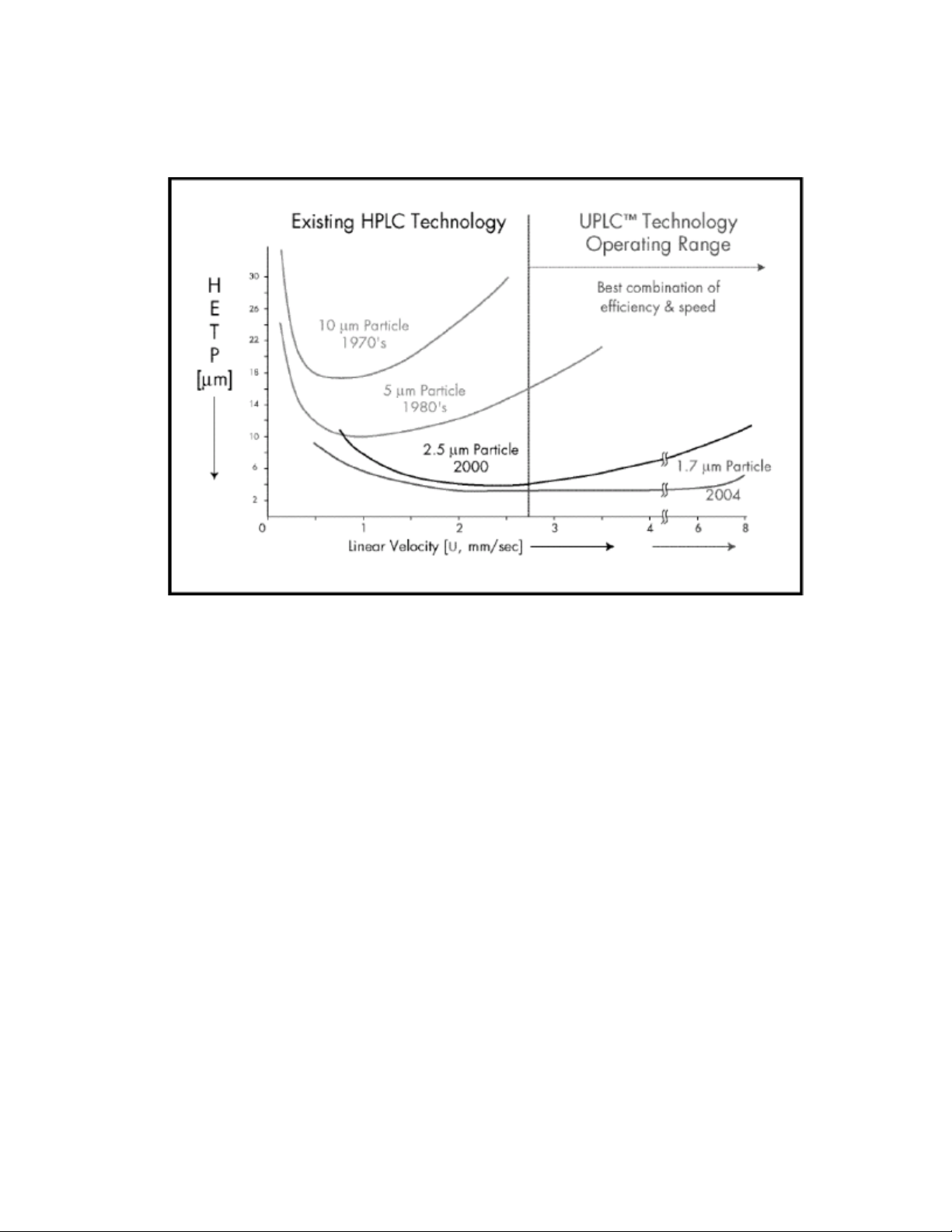
Figure 1–1: Evolution of particle size in liquid chromatography and the impact on
separation efficiency
It is apparent from the figure, above, that using 1.7-µm particles achieves higher efficiency that
persists as flow rate increases (lower HETP indicates higher efficiency). When operating in this
area of the plot, the peak capacity and the speed of a separation can set limits well beyond those
of conventional HPLC technology.
April 4, 2018, 715005704 Rev. A
Page 14

Figure 1–2: Comparison of chromatographic separations using 5.0-µm and 1.7-µm
particles
The figure above compares two separations, one using HPLC with a column packed with 5 µm
particles, and the other using UPLC with a column packed with 1.7 µm particles. The
improvements in both resolution and the speed of analysis are apparent in the UPLC
chromatogram. Each separation was performed on a 2.1 × 50 mm column. Chromatographic
conditions for the separations were identical, except for the flow rate, which was scaled based on
particle size.
1.2 Features of the ACQUITY UPLC I-Class Series system
The ACQUITY UPLC I-Class Series system significantly improves the results of traditionally
challenging separations.
When compared to systems typically used for difficult assays, the I-Class Series system offers
these advantages:
• Significantly decreased system dispersion
• Rapid injection cycles and sample throughput
• Greatly reduced carryover
These advantages provide the following benefits over traditional systems:
April 4, 2018, 715005704 Rev. A
Page 15

• Superior peak capacity
• Higher sensitivity
• Faster data acquisition
• Consistent, reproducible results
The I-Class Series system is an effective tool for analyzing complex or dilute samples, providing
high resolution and reproducible results for chromatographic separations.
1.3 Binary solvent manager
The ACQUITY UPLC I-Class Series system employs a binary solvent manager that, like the
system, is optimized for sub-2-μm particle liquid chromatography and uses reduced fluid
volumes. New pressure management capabilities extend the flow rate envelope for the system to
support ballistic gradients. This support enables you to run higher flow rates and faster cycle
times to accelerate your chromatography, while maintaining the integrity of the separation.
1.4 Column compartments
Column compartments configured with ACQUITY UPLC I-Class Series systems ensure reliable
and robust separations. This is especially important when you transfer methods to other systems.
UPLC applications can benefit from pre-column, mobile-phase heating to improve
chromatographic separations.
The ACQUITY UPLC I-Class Series column compartments use an active preheater to condition
solvent as it enters the column. The preheater is a heat source that raises the temperature of the
incoming mobile phase and injected sample to the same set point as that of the column
compartment. Active solvent preheaters provide precise thermal performance with low dispersion
for exact control of chromatographic conditions that remain consistent between systems.
1.5 Injector mechanisms
ACQUITY UPLC I-Class Series system configurations include a sample manager with either a
fixed-loop or flow through needle injector mechanism. This flexibility allows you to choose the
optimum injector mechanism for your application. Both mechanisms provide high precision with
low dispersion and efficient sample recovery. The low carryover performance of the injector
mechanisms, which enables you to use a wider sample concentration range, is also beneficial for
mass spectrometry applications.
April 4, 2018, 715005704 Rev. A
Page 16

1.6 Mass spectrometry
When you configure an ACQUITY UPLC I-Class Series system with a mass spectrometer, the
system’s design enhancements enable you to separate more peaks with better peak shapes to
aid quantitation. You also benefit from improvements in sensitivity and flexibility.
See also: Waters.com for more information on compatible Waters mass spectrometers.
1.7 System components
The following illustration depicts a system stack that includes four core modules and the solvent
bottle tray.
Figure 1–3: Example of an I-Class Series system core stack
Solvent bottle tray
Detector
April 4, 2018, 715005704 Rev. A
Page 17

Column heater
Sample manager
Binary solvent manager
The ACQUITY UPLC I-Class Series core system includes a binary solvent manager, a sample
manager - flow through needle or sample manager - fixed loop (SM-FTN or SM-FL), a column
heater (CH-A), detectors (tunable ultraviolet, photodiode array, eλ photodiode array, or mass
spectrometry), and an ACQUITY UPLC column.
Waters Empower chromatography data software, MassLynx mass spectrometry software, stand-
alone ACQUITY UPLC Console software, or Analyst software controls the system.
1.7.1 Binary solvent manager (BSM)
The Waters ACQUITY UPLC I-Class Series binary solvent manager (BSM) delivers solvent
compositions for isocratic and binary gradient methods at flow rates of 0.01 to 2.0 mL per minute.
Its features include in-line filters upstream of a primary check valve, the Waters Intelligent Intake
Valve (i2Valve), automated priming functions, and daily system-setup routines.
The design of the binary solvent manager is optimized for sub-2-μm particle liquid
chromatography. The upper pressure limit is set at 124,106 kPa (1241 bar, 18,000 psi) per pump.
A maximum flow rate of 1 mL/min is permitted at system backpressures to 124,106 kPa (1241
bar, 18,000 psi), which falls within the range of optimal linear velocity for sub-2-μm particle
columns of ID 1.0 mm to 3.0 mm.
See also: ACQUITY UPLC Binary Solvent Manager PLUS Overview and Maintenance Guide on
your documentation media, or at Waters.com, for more details.
Note: An optional degasser vent line extension exists for applications requiring longer tubing
lengths. For more information, contact your local Waters distributor.
1.7.2 Sample manager-FTN (SM-FTN)
The ACQUITY UPLC I-Class Series sample manager - flow through needle (SM-FTN) differs
from a loop-based injector. The mechanism aspirates a sample from plates and vials and holds it
in the sample needle in preparation for injecting the sample onto the column. The needle serves
as part of the injection flow path when the sample is pushed onto the column.
Optional extension loops (installed between the sample needle and the injection valve) can
increase the injection volume beyond that of the sample needle. The SM-FTN can also dilute
samples using the auto-dilution option.
Using the flow through needle (FTN) mechanism, the system operates similarly to most traditional
HPLC systems, which facilitate the transfer of HPLC methods. The FTN mechanism also does
not require you to learn new injection modes. Also, it achieves injection accuracy and decreases
April 4, 2018, 715005704 Rev. A
Page 18

cycle time for small volume injections. Gradients pass through the needle during injection,
ensuring complete sample recovery.
1.7.3 Sample manager-FL (SM-FL)
The sample manager - fixed loop (SM-FL) uses a loop-based mechanism to inject samples. After
a puncture needle pierces the well or vial covering, a sample needle emerges from within the
puncture needle to aspirate the sample. In the partial loop needle overfill injection mode (default),
the sample needle is then removed from the vial and the sample syringe continues to pull the
sample aliquot through the sample needle and through the injection valve until any pre-sample
and the sample injection volume pass through the injection valve. The valve actuates, switching
the sample loop to the load position. The sample is pushed back toward the needle and the
sample volume is then pushed into the sample loop. The sample loop is moved to the injection
position and flow from the pump pushes the sample onto the column.
See also: ACQUITY UPLC Sample Manager - Fixed Loop PLUS Overview and Maintenance
Guide on your documentation media, or at Waters.com, for more information on other injection
modes.
1.7.4 Column heater (CH-A)
Column temperature variations can shift peak retention times and alter peak shapes, increasing
the difficulty of achieving precise results. The ACQUITY UPLC I-Class Series system’s column
heater (CH-A) helps to ensure precise, reproducible separations by controlling the column
temperature. The CH-A heats the column compartment to any temperature from 20 ºC to 90 ºC,
that is at least 5 °C above the ambient temperature. A low dispersion, active preheating device
heats the incoming solvent before it enters the column. The column compartment can
accommodate columns of up to 4.6-mm I.D. and up to 150-mm length.
1.7.5 30-cm Column heater (optional)
The optional 30-cm column heater (CH-30A) heats the column compartment to any temperature,
from 20 ºC to 90 ºC, that is at least 5 ºC above the ambient temperature. The CH-30A mounts on
the side of the system stack.
The CH-30A can accommodate UPLC columns of 4.6 mm, or less, ID and 150 mm, or less,
length and HPLC columns of 4.6 mm, or less, ID and 300 mm, or less, length. For columns that
exceed 4.6 mm ID, use the ACQUITY UPLC 30-cm column heater/cooler (30cm CHC) with the
appropriate compatibility kit.
Note: The ACQUITY UPLC 30cm CHC is compatible with ACQUITY UPLC I-Class Series
systems. See ACQUITY UPLC Column Compartments Operator's Overview and Maintenance
Information on your documentation media, or at Waters.com, for details.
April 4, 2018, 715005704 Rev. A
Page 19

1.7.6 Column manager (optional)
The ACQUITY UPLC I-Class Series column manager (CM-A) is an option for helping to ensure
precise, reproducible separations. The CM-A can regulate the temperature of columns from 4 °C
to 90 °C. Its troughs can accommodate columns of up to 4.6-mm I.D. and up to 150-mm length,
depending on the configuration. Each of the two column troughs can hold one column, up to 150
mm in length (with filter or guard column). The CM-A also offers a bypass channel and
automated, programmable switching between columns (for methods development), and is
installed with two column switching valves.
Restriction: The minimum achievable column compartment temperature set point must not be
greater than 25 °C below the ambient temperature.
Tip: You can use the CM-A for column switching and two-dimensional chromatography
applications. For information about two-dimensional applications, consult the ACQUITY UPLC
Systems with 2D Technology Capabilities Guide.
1.7.7 Column heater/cooler (optional)
The 30-cm column heater/cooler (CHC) module compartment temperature is settable from 4.0 to
65.0 ºC, in 0.1 ºC increments. Compartment controllable temperatures range from 15 ºC below
ambient to 65.0 ºC.
The 30-cm CHC module shares many of the same components with the 30-cm CH module,
except for a thermoelectric engine for heating and cooling, and an additional fan for exhausting
engine heat. In addition, the 30-cm CHC module incorporates an internal onboard power supply,
external power-entry module, and power on/off switch. The power supply is necessary for
additional power required to operate the thermoelectric heater/cooler engine circuit. Additionally,
the 30-cm CHC module is fitted with a standard, passive preheater module and supports the
optional 3-position column-selection valve.
Restriction: You cannot use the 30-cm CHC module's passive preheater simultaneously with
the optional column-selection valve.
1.7.8 Column Module Switch Box (optional)
With the optional Waters Column Module Switch Box, you can physically connect a column
heater (CH-A) and a 30-cm column module (either a CH-30A or a 30-cm CHC) to the sample
manager - flow-through-needle (SM-FTN) and switch the electrical control of the column modules
via the SM-FTN console.
The switch box is mounted to the rear of the SM-FTN. The SM-FTN interconnect cable is
connected to the sample manager (SM) port of the switch box, the CH-A interconnect cable is
connected to the CH-A port, and either the CH-30A or the 30-cm CHC interconnect cable is
connected to the 30-cm port.
April 4, 2018, 715005704 Rev. A
Page 20
Table of contents
Other Waters Water System manuals

Popular Water System manuals by other brands


Wilo
Wilo Stratos PICO Installation and operating instructions

Sears
Sears 390.250095 owner's manual

Cetetherm
Cetetherm Midi Compact SR144 Installation, service and operating instruction

Halsey Taylor
Halsey Taylor HVRGRN8WSNF 1B Series Installation, care & use manual

Hellenbrand
Hellenbrand ProMate 6.5 brochure

Grundfos
Grundfos UPSe instructions

salmson
salmson C1000N Installation and starting instructions

WaterLogic
WaterLogic 12-WL200CT manual

Barnstead International
Barnstead International NANOpure DIamond 1192 Series Operation manual

SIGELOCK
SIGELOCK SPARTAN Operation and maintenance guide

Cuno
Cuno SQC Series owner's manual

Istore
Istore 180L installation manual