MP sava3 User manual
Technical Manual
V700 –11/2017
MTMECMPsava3_700_EN
Installation • Assembly • Start-Up
Use • Maintenance • Repair
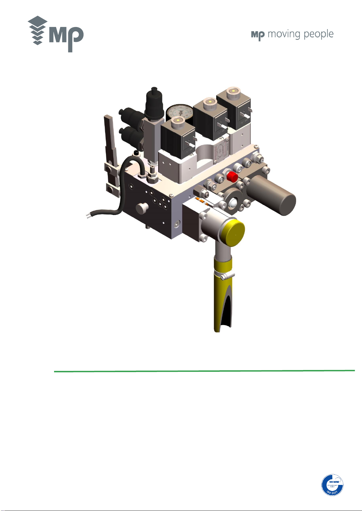
HYDRAULIC POWER UNIT 1 ¼” 1 ½”
MP sava3

MP sava3 Hidraulic Power Unit 1 ¼” 1 ½”
V700 - 11/2017
2/40
MTMECMPsava3_700_EN
SUMMARY OF MODIFICATIONS IN REGARD WITH THE PREVIOUS VERSION:
INDEX
SECTION
DESCRIPTION OF THE
MODIFICATION
MODIFICATION CONCERNING
Physical
Product
Functions
Features
Figures
Writing
8.
The “Pressure test” for
commissioning as per
standards
EN 81-2 and EN 81-20 has
been inserted
MTHDsava3_600

MP sava3 Hidraulic Power Unit 1 ¼” 1 ½”
V700 - 11/2017
3/40
MTMECMPsava3_700_EN
TABLE OF CONTENTS
0 •INDIVIDUAL PROTECTION EQUIPMENT ....................................................................................................................................................................................4
1 •HYDRAULIC POWER UNIT...........................................................................................................................................................................................................4
1.1. Mechanical assembly..................................................................................................................................................................................................................4
1.2. Types of pipe couplings...............................................................................................................................................................................................................5
1.3. Process for joining steel pipes ....................................................................................................................................................................................................5
1.4. Steel pipes and flexible hoses.....................................................................................................................................................................................................6
1.5. Rupture valve ..............................................................................................................................................................................................................................6
1.6. Electrical connections for 3-phase motors ¡Error! Marcador no definido. ..................................................................................................................................7
1.7. Sart-up.........................................................................................................................................................................................................................................8
2 •BLOCK OF VALVES .....................................................................................................................................................................................................................8
2.1. MP sava3 Valve Block according to 2014/33/EU European Standard.......................................................................................................................................9
2.1.1. Description of valves.............................................................................................................................................................................................................9
2.1.2. Unit operation .......................................................................................................................................................................................................................9
2.1.3. Hydraulic circuit MP sava3 Valve Block with Soft-Stop according to European Directive 2014/33/EU ............................................................................10
2.1.4. Adjustment of Valves..........................................................................................................................................................................................................11
2.1.5. Testings ..............................................................................................................................................................................................................................12
2.2. MP sava3 Valve Block...............................................................................................................................................................................................................14
2.2.1. Description of Valves..........................................................................................................................................................................................................14
2.2.2. Unit operation .....................................................................................................................................................................................................................14
2.2.3. Hydraulic circuit (Valid for Standard and Y- D configurations).........................................................................................................................................15
2.2.4. Valve adjustment................................................................................................................................................................................................................15
2.3. MP sava3 Valve Block SOFT-STOP.........................................................................................................................................................................................16
2.3.1. Description of Valves..........................................................................................................................................................................................................16
2.3.2. Unit operation .....................................................................................................................................................................................................................16
2.3.3. Hydraulic circuit MP sava3 + Soft-Stop..............................................................................................................................................................................17
2.3.4. Valve adjustment................................................................................................................................................................................................................17
3 •OIL COOLING DEVICE ...............................................................................................................................................................................................................18
3.1 Oil cooling device connections - Hydraulic power unit...............................................................................................................................................................18
3.2. Oil cooler and thermal switch wiring..........................................................................................................................................................................................19
4 •TANK OIL HEATER.....................................................................................................................................................................................................................19
5 •MAINTENANCE...........................................................................................................................................................................................................................19
5.1. Cleaning of the reutrn oil filter...................................................................................................................................................................................................20
5.2. General checks..........................................................................................................................................................................................................................20
6 •CONTROLS ..................................................................................................................................................................................................................................21
7 •COMMISSIONING TEST RELATED TO UNINTENDED CAR MOVEMENT (UCM) AS PER EN 81-2 & EN 81-20 .................................................................22
7.1. Preliminary requirements ..........................................................................................................................................................................................................22
7.2. Failure simulation of the VB valve (Descent valve operated by the YD Electrovalve).............................................................................................................22
7.2.1. Failure simulation of the VB valve in ascent ......................................................................................................................................................................22
7.2.2. Failure simulation of the VB valve in descent ....................................................................................................................................................................22
7.3. Failure simulation of the VD valve (Bypass valve operated by the YS Electrovalve)...............................................................................................................23
7.4. Test of the monitoring system...................................................................................................................................................................................................23
8 •COMMISSIONING WITH A PRESSURE OF 200% FULL LOAD, AS PER EN 81-2 AND EN 81-20.......................................................................................24
A. APPENDIX •ACTIONS TO FACE MALFUNCTIONS................................................................................................................................................................25
A1. Introduction ................................................................................................................................................................................................................................25
A2. Ascent ........................................................................................................................................................................................................................................27
A2.1. Start-up (the lift does not start)............................................................................................................................................................................................27
A2.2. Nominal speed (a slower speed than usual).......................................................................................................................................................................29
A2.3. Levelling speed (does not function correctly) .....................................................................................................................................................................30
A3. Descent......................................................................................................................................................................................................................................31
A3.1. Start-up (the lift does not start) .....................................................................................................................................................................................31
A3.2. Nominal speed ....................................................................................................................................................................................................................31
A3.2.1. Speed slower than usual..............................................................................................................................................................................................31
A3.2.2. Speed higher than usual...............................................................................................................................................................................................32
A3.3. Levelling speed (does not work or does not reach the correct speed)...............................................................................................................................32
4. At floor ..........................................................................................................................................................................................................................................33
A4.1.The lift descends continuously.............................................................................................................................................................................................33
A4.2.The lift descends when loaded.............................................................................................................................................................................................34
A5. Miscellany ..................................................................................................................................................................................................................................34
A6. Electric Motors, Operating Instructions......................................................................................................................................................................................36
MP sava3 Hidraulic Power Unit 1 ¼” 1 ½”
V700 - 11/2017
4/40
MTMECMPsava3_700_EN
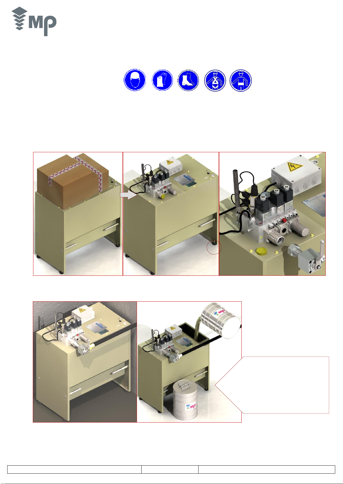
1. The power unit packaging contents the fitting box. Unpack all the assembly and place the
power unit at the final position at the installation correctly supports on its four anti-vibration rubber
feet.
2. Fit the lever of the hand pump and connect the
shut-off valve to the input of the power unit
(cylinder and power unit fitting boxes).
0 •INDIVIDUAL PROTECTION EQUIPMENT
Neither the tools nor the individual protection equipment are included in the pack.
Individual Protection Equipment
Helmet
Anti-cut gloves
Reinforced boots
Safety belt
Goggles or shield
Back belt
1 •HYDRAULIC POWER UNIT
1.1. Mechanical assembly
3. Take the hydraulic hose from the hole to connect to
the power unit and to the rupture valve on the cylinder.
4. Fill the tank
STEPS TO FOLLOW
a) Remove the tank cover and check the
cleaning of the tank (dry and no dust)
b) Fill the tank with hydraulic oil avoiding making
bubbles.
c) The oil level must be at least 10 cm higher
than the motor surface level at the moment of
maximum expansion of the cylinder.
MP sava3 Hidraulic Power Unit 1 ¼” 1 ½”
V700 - 11/2017
5/40
MTMECMPsava3_700_EN
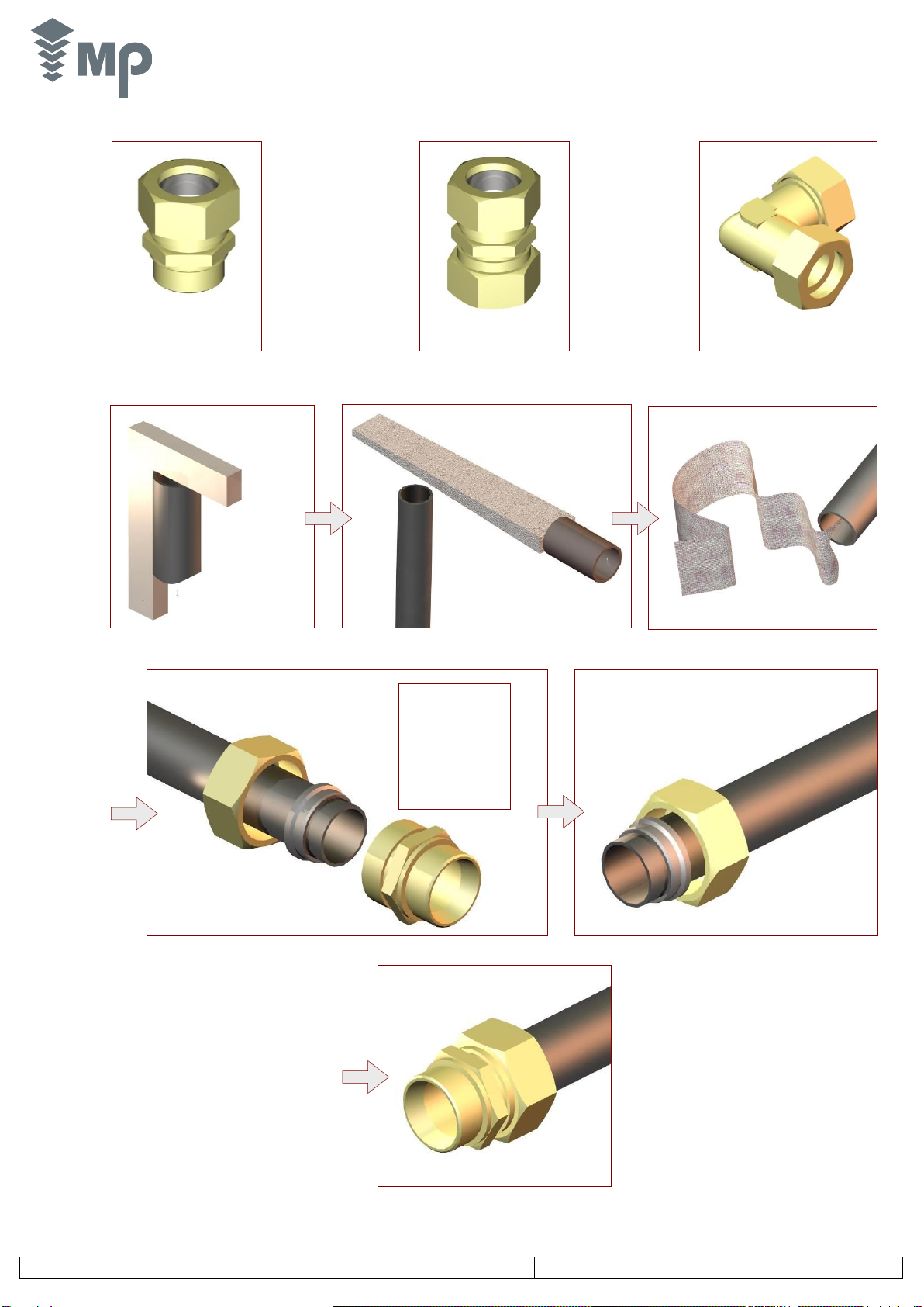
1.2. Types of pipe couplings
1.3. Process for joining steel pipes
UDA (double clasp)
To join pipe to valve block
(end coupling)
USA (single clasp)
To join pipe to valve block
(end coupling)
CODO (double clasp elbow at 90º)
To join a steel pipe and a hose
Cut hose perfectly square
Use a saw; do not use
a hose cutter
Remove burrs inside and outside
Clean the hose inside
with a non-fray cloth
Fit nut and ring to the
pipe in the shown order
- Screw on the cap
nut by hand as much
as possible
- Push the pipe up
against the bottom of
the coupling.
- Tighten the nut with
a spanner 1,5 turns;
the pipe must not be
able to rotate.
Oil the cutting ring
Cutting edge of the ring
towards the end of the pipe
Unscrew the cap nut
and check that the ring
is firmly gripping the
hose
Fully tighten

MP sava3 Hidraulic Power Unit 1 ¼” 1 ½”
V700 - 11/2017
6/40
MTMECMPsava3_700_EN
1.4. Steel pipes and flexible hoses
1.5. Rupture valve
FLEXIBLE HOSE ONLY
FLEXIBLE HOSE AND
STEEL PIPE
Avoid up and down
curves in the course of
the hose
IMPORTANT:
Use for lengths > 10 m.
Assemble a piece of Flexible Pipe
behind the Rupture Valve as well as
between the Rigid Pipe and Power
Unit.
Recommended for lengths ≤ 10 m
Avoid leaving the hose completely straight
Remove the protective plate and seal paper
Check the o-ring seal
is properly placed in
its housing
In case of double cylinder installation,
connect the rupture valves each other
by using a Ø6mm steel pipe (fitting
box).
Fix steel or flexible pipe.
Use the cap nut and cutting ring
for steel pipe or flexible hose
with steel tube end
MP sava3 Hidraulic Power Unit 1 ¼” 1 ½”
V700 - 11/2017
7/40
MTMECMPsava3_700_EN
NOTE:
Once the installation is finished, check the motor turns to the ‘right’; should it turn to the left, the pump is very noisy. In this case, reverse the polarity of the
motor wiring (change two of the phases).
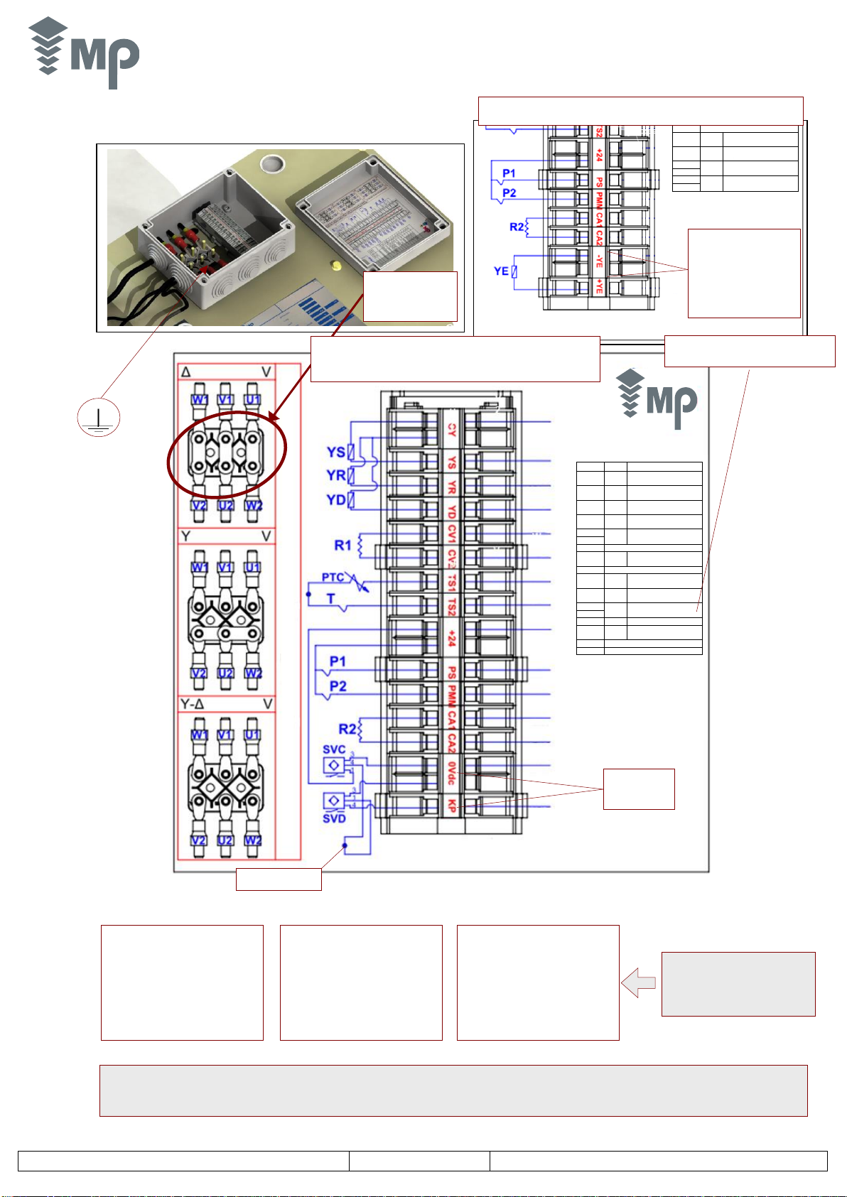
1.6. Electrical connections for 3-phase motors ¡Error! Marcador no definido.
CY
Común electroválvula
Common Electrovalve
YS
Electroválvula YS
Electrovalve YS
YR
Electroválvula YR
Electrovalve YR
YD
Electroválvula YD
Electrovalve YD
CV1
R1
R. Calentamiento Valv.
V.Block Heater
CV2
TS1
PTC
TS2
T
Termosonda
T.Switch
+24
VDC
PS
P1
Presostato
P.Switch
PMM
P2
Presostato.Pmax/Pmin
P.Swith. Pmax/Pmin
CA1
R2
Resistencia. Depósito
Tank Oil Heater
CA2
0Vdc
0Vdc
KP
Salida sensores
Output Sensors
SVC
SVC Sensor
SVD
SVD Sensor
Y- D Connection
Motors star-delta connected:
50 Hz
- 230/400 (mains 230 V).
- 400/690 (mains 400 V).
- 415/720 (mains 415 V).
60 Hz
- 220/380 (mains 220 V)
- 380/660 (mains 380 V)
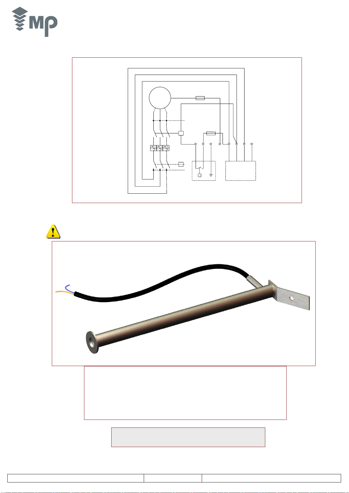
Submerge the heater resistance into
the oil (Optional component)
Motor is supplied
according to the
customer
specifications.
U
2
W
1
V
1
U
1
D Connection
Motors delta connected:
50 Hz
- 230/400 (mains 230 V)
- 400/690 (mains 400 V)
- 415/720 (mains 415 V)
60 Hz
- 220/380 (mains 220 V)
- 380/660 (mains 380 V)
Y Connection
Motors star connected:
50 Hz
- 230/400 (mains 400 V).
60 Hz
- 220/380 (mains 380 V).
Warning:
Y-Dstarting is possible only if the
motors are wound for the voltages
shown in these diagrams.
EN 81-2+A3
EN 81-20
2014/33/EU
CONNECTION
THE EMERGENCY
VALVE WILL NOT BE
INCLUDED IN POWER
UNITS THAT SHOULD
BE IN ACCORDANCE
WITH THE EN 81-2+A3
AND EN 81-20
STANDARD
Connection according to EN 81-2+A3
and EN 81-20/50
+24
VDC
PS
P1
Presostato
P.Switch
PMM
P2
Presostato.Pmax/Pmin
P.Swith. Pmax/Pmin
CA1
R2
Resistencia. Depósito
Tank Oil Heater
CA2
-YE
Electroválvula YE
Electrovalve YE
+YE
Connection considering Emergency Valve
1: Marrón/Brown
4: Negro/Black
3: Azul/Blue
VIOLETA
VIOLET
NEGRO
BLACK
AMARILLO
YELLOW
AMARILLO
YELLOW
MARRÓN
BROWN
BLANCO/AZUL
WHITE/BLUE
ROJO
RED
BLANCO
WHITE
BLANCO
WHITE
VERDE
GREEN
VERDE
GREEN
AZUL
BLUE
NARANJA
ORANGE
ROSA
PINK
GRIS
GREY
MP sava3 Hidraulic Power Unit 1 ¼” 1 ½”
V700 - 11/2017
8/40
MTMECMPsava3_700_EN
1.7. Sart-up
1. The oil supply line (flexible hose or steel pipe) should be as short as possible and without sharp bends.
2. Make sure the pipe is in line with the connection and the joints are made as indicated in the technical manual.
3. Before assembling the pipe line, make sure the pipes are smooth and deburred. Clean the inside of the pipes with a lint free rag.
4. Loosen the air bleeder screw in the cylinder head.
5. Rotate the pump at low speed until oil comes out of the air bleeder hole. Then close and tighten the oil bleeder screw.
6. During the installation, repeat the bleeding operation to remove any accumulated air.
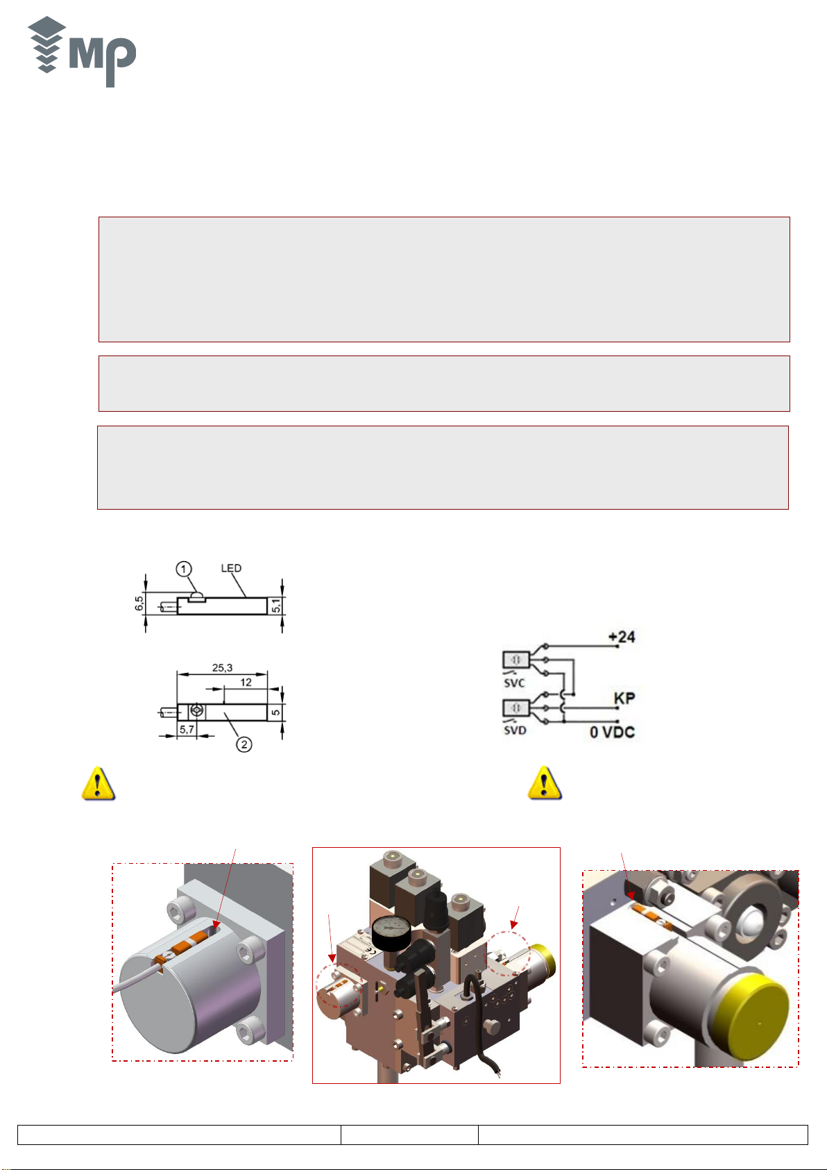
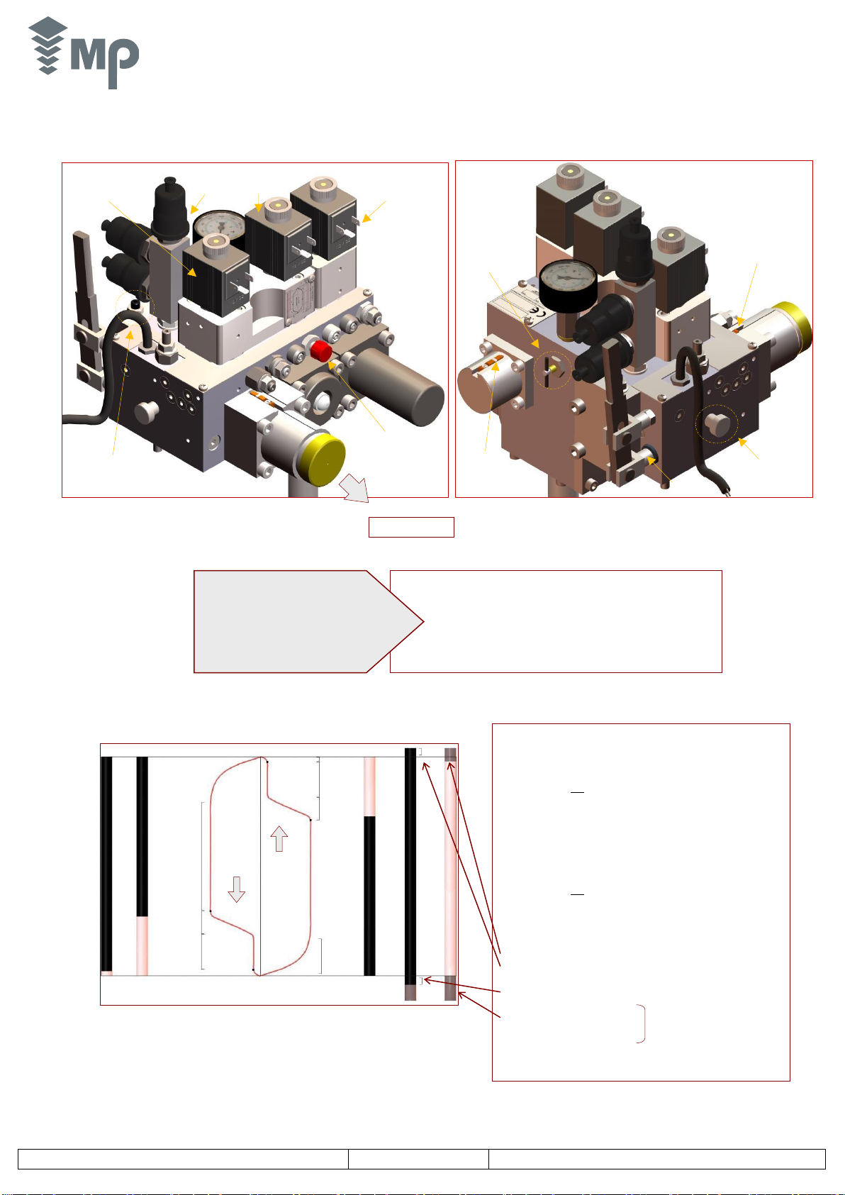
1.8 Wiring of Magnetic Sensors.
NOTE:
•Before pouring oil into a tank which may have been exposed to excessive humidity or opened to the air, remove the cover and check there are no trace of
moisture. Dry out the tank if necessary.
•Switch on the motor to check the turning direction. If the noise coming from the unit is excessive, the motor may be turning in the opposite direction.
•If the temperature of the machine room is very cold or very wet, the oil has to be heated.
•The manometer should be connected only when used by the installer.
•Check the rupture valve.
•After all adjustments have been made, seal the caps of all the valves.
NOTE:
•YS the name of this valve is defined by the chosen configuration equipment. Then it will be:
-Y-D Electrovalve. - Soft-Stop Electrovalve.
VERY IMPORTANT
The factor service of our motors is 40%. Consequently, in inspection speed, you have to remember that, during one minute time, the lift will be working for
20 seconds and resting for 40 seconds.
In the same way, during any t time period, it will be working for 0,4 t and resting for 0,6 t.
1 Brown
2 Black
3 Blue
1: Eccentric fixing
2: Active area
MAGNETIC
SENSOR
DESCENT VALVE
SVD
MAGNETIC
SENSOR
BYPASS VALVE
SVC
3
3
2
2
1
1
SENSOR STOP
SVC
SENSOR STOP
SVD
Proper position of Sensor SVC:
The lift being in idle state, the sensor
SVC shall be located as far as possible
to the limit and its led shall be lit
Proper position of Sensor SVD:
The lift being in idle state, the sensor
SVC shall be located as close as
possible to the limit and its led shall be lit
MP sava3 Hidraulic Power Unit 1 ¼” 1 ½”
V700 - 11/2017
9/40
MTMECMPsava3_700_EN
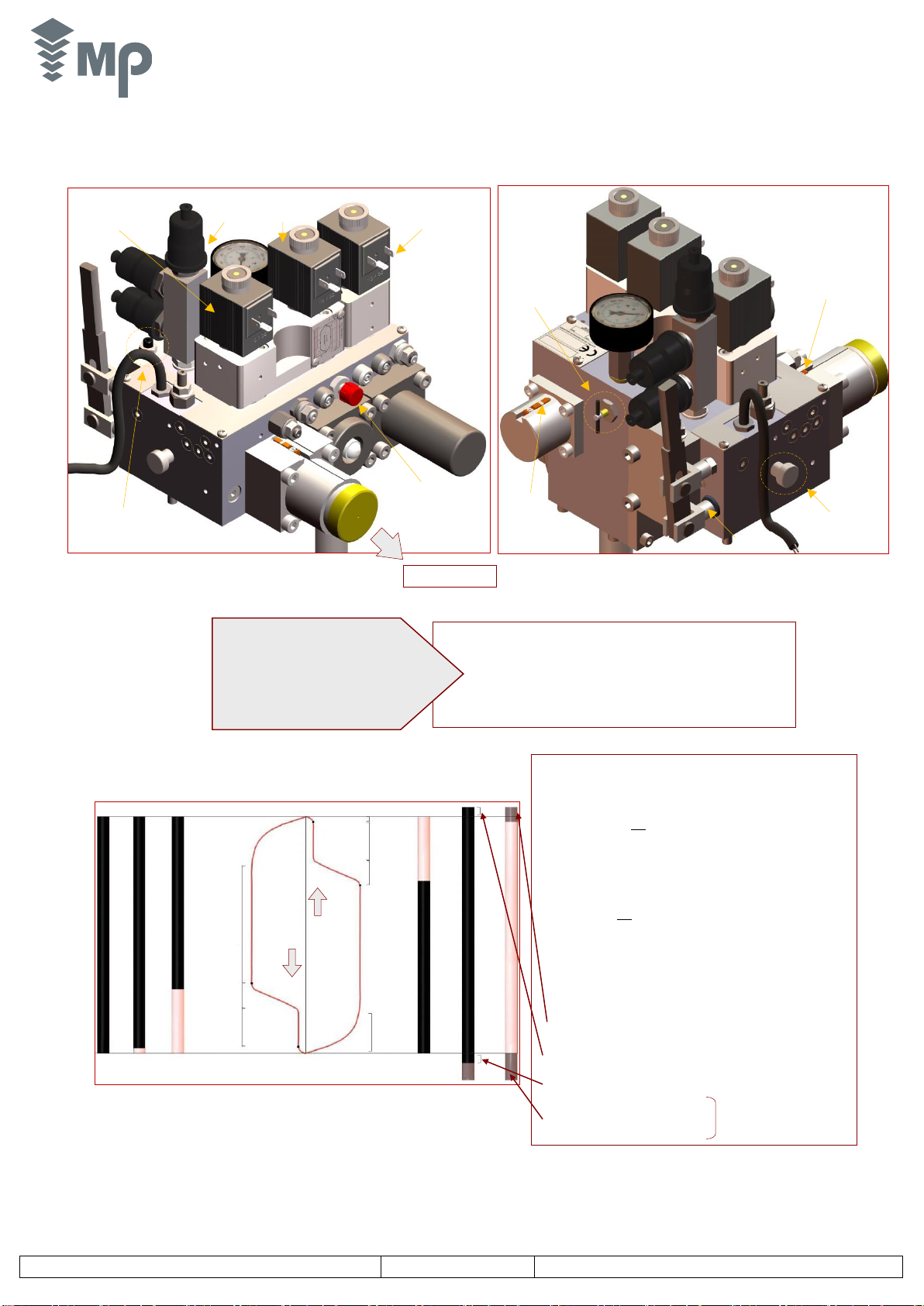
A Point Upwards deceleration signal.
Place at an S distance from the floor level equal to
B Point Disconnected motor signal.
C Point Downwards deceleration signal.
Place at an S distance from the floor level equal to
D Point YD Electrovalve disconnection signal
Connected
Adjustment
FLOOR
Adjustment
YR
FLOOR
MOTOR
YR
YS-A3
4
3
2
5
3
4
A
B
C
D
YD
Connected
Change to D
Connect in Y for 2 seconds approx.
Y- D
Starting
UPWARDS
DOWNWARDS
YS Electrovalve will be connected just before getting to the floor
Motor will remain connected for 2 seconds after the lift stops
For direct starting, motor idle time approx. 0,5 seconds
YS-A3
2 •BLOCK OF VALVES
2.1. MP sava3 Valve Block according to 2014/33/EU European Standard
2.1.1. Description of valves
2.1.2. Unit operation
1: Pressure relief valve adjustment
2: Upwards acceleration adjustment
3: Upwards/downwards acceleration adjustment
4: Levelling speed adjustment
5: Down speed adjustment
6: Cylinder minimum pressure adjustment.
7: Relief valve adjustment into hand pump.
Names of adjusting screws
YD Electrovalve
(descent)
+ YE (emergency)
YR Electrovalve
(for speed
change)
Pressure switch
with adjustment
screw
Testing screw
of the rupture
valve
Manual lowering
pushbutton
Hand pump
bleeding
Manometer
protection key
1
6
TO CYLINDER
Starting
Electrovalve YS
(-A3 optional)
Hand
pump
lever
5
4
3
2
7
Magnetic Sensor
Descent Valve
SVD
Magnetic Sensor
Bypass Valve
SVC

MP sava3 Hidraulic Power Unit 1 ¼” 1 ½”
V700 - 11/2017
10/40
MTMECMPsava3_700_EN
VR. Non return valve Screw 1: Pressure relief valve adjustment (maximum pressure)
VA. Starting valve Screw 2: Upwards acceleration adjustment.
VD. Bypass valve Screw 3: Upwards/downwards deceleration adjustment.
VC. Flow regulator valve Screw 4: Levelling speed adjustment.
VB. Descent valve Screw 5: Down speed adjustment.
YR. Electrovalve for changing speed Screw 6: Hand pump relief valve adjustment.
YD. Descent Electrovalve Screw 7: Cylinder minimum pressure adjustment.
YS. Y- ΔStarting Electrov. (YS-A3 2014/33/EU) Integrated Soft-Stop SVC: YS-A3 Valve magnetic Sensor.
VP. Balancing down pressure switch SVD: Descent Valve YD magnetic Sensor
VL. Pressure relief valve
CP. Maximum pressure switch (optional)
VM. Manual descent valve
VG. Valve to control the minimum pressure in cylinder
Return filter-Shut-off valve
MP sava3 Valve Block
Rupture valve
Hand pump
2.1.3. Hydraulic circuit MP sava3 Valve Block with Soft-Stop according to European Directive 2014/33/EU
svc
SVD

MP sava3 Hidraulic Power Unit 1 ¼” 1 ½”
V700 - 11/2017
11/40
MTMECMPsava3_700_EN
NOTE: If the lift does not go up, check the pressure relief valve or the
maximum pressure switch are not operating; see points 1 and 2 of section 4.5
Adjustment screws with seal-locks:
- Loosen the nut before adjusting
- Tighten the nut after adjusting
NOTE: The power unit
information plate shows,
beside every adjustment
screw, the quantity increase
or decrease direction of the
parameter that controls this
adjuster and its name as well.
2.1.4. Adjustment of Valves
1. Upwards acceleration adjustment. Screw 2
1. Load the lift car with half the rated load.
2. Tightening screw 1 makes starting gentler (- accelerated). If screw 1 is tightened fully, the lift will not start-up.
3. Loosening screw 1 makes the lift starts up more quickly and therefore abrupter (+ accelerated).
2. Down speed adjustment. Screw 5
1. Load the lift car with half the rated load. Time how long it takes the lift car to travel down.
2. If the speed is higher than required, loosen screw 5 until desired speed is obtained (- speed).
3. If the speed is lower than required, tighten screw 5 so that down speed increases (+ speed).
3. Upwards and downwards deceleration adjustment. Screw 3
1. Load the lift car with half the rated load.
2. Tightening screw 3 makes the change smoother (- accelerated); it also reduces the time at the levelling speed for a distance of the change signal.
3. Loosening screw 3 makes the change more abrupt (+ accelerated); it also increases the time at the levelling speed for a distance of the change signal.
4. Levelling speed adjustment. Screw 4
1. Load the lift car with half the rated load.
2. Tightening screw 4 reduces the speed, the lift stops smoothly (- speed). ‘If the speed is too low, it could jerk’.
3. Loosening screw 4 increases the speed; the lift stops abruptly (+ speeds).
4. Time at levelling speed depends on the position of contacts in the lift shaft and the adjustment of screw 3.
5. Soft-Stop adjustment. Screw 8. Available in 1 ½” Hydraulic Equipment
1. Load the lift car with half the rated load.
2. Tightening Soft-Stop screw, the lift stops smoothly.
3. Loosening Soft-Stop screw, the lift stops abruptly.
NOTE: All the blocks are adjusted prior to delivery; this information must only be used if a re-adjustment of a valve block is required.
Hand pump pressure
relief valve
MP sava3 Hidraulic Power Unit 1 ¼” 1 ½”
V700 - 11/2017
12/40
MTMECMPsava3_700_EN
2.1.5. Testings
1. Pressure relief valve. Screw 1
1. Load the lift car with 100% of the rated load.
2. Open the manometer protection key and take the pressure reading (full load pressure).
3. Close the shut-off valve and disconnect the maximum pressure reading switch from the circuit if any.
4. Send the lift up and make a note of the manometer reading once it is stabilized (tripping pressure).
5. This pressure should be 1,4 times the full load pressure.
6. If the pressure is not correct, tighten screw 1 to increase the tripping pressure (+ pressure) or loosen to reduce it (- pressure).
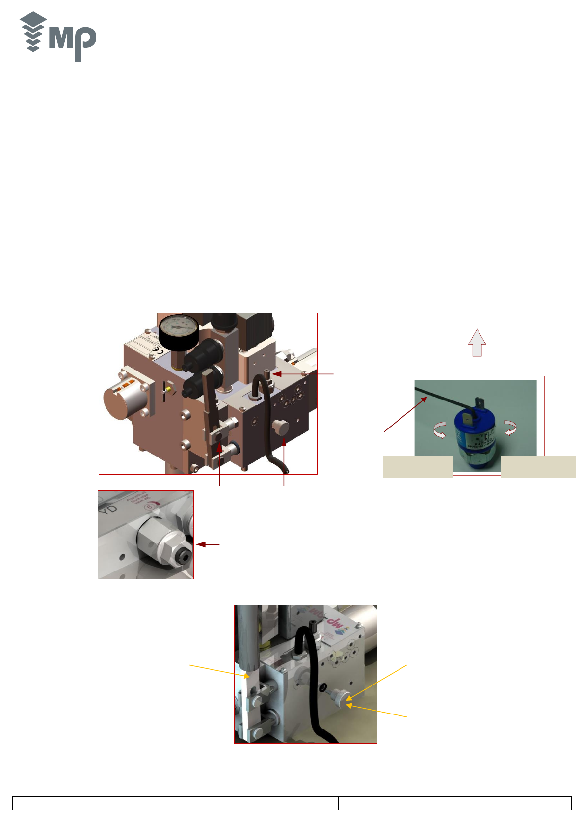
2. Maximum or minimum pressure switch (optional)
1. Close the shut-off valve and send the lift up.
2. Note the cut-off pressure; it should be between 1,1 and 1,2 times the full load pressure.
3. If it is not correct, adjust the pressure switch using an appropriate screwdriver; see figure below.
3. Hand pump. Screw 7
1. Pump the lever and check the lift goes up.
2. If not, the hand pump needs priming. To do this, pump the lever while loosening and tightening the bleeding screw several times, until an opposition in
movement is observed. Then tighten the screw.
3. To check the tripping pressure of the relief valve:
-Close the shut-off valve and cut off the power.
-Pump the lever and note the manometer reading after it is stabilized.
-Pressure should be 2,3 times the full load pressure.
-Should it not be correct, tighten the relief valve screw to increase the tripping pressure, or loosen to reduce it.
Bleeding Hand Pump
Hand pump
lever
Relief valve screw (7)
Bleeding
screw
Cylinder minimum
pressure adjustment (6)
Allen Wrench hex.
2 mm
Unscrew a few turns the
Bleeding Screw. It is not
necessary unscrew it
completely
Repeat the pump
several times to ensure
the bleeding of the
hydraulic circuit.
Turn left to decrease
the acting pressure
Turn right to increase
the acting pressure
Remove the cap
Open and close several
times the Bleeding Screw
and, at the same time, start
to pump by acting on the
lever of the Hand-Pump.
Pump with the hand pump and close the bleeding Screw
when the hand pump is loaded.
MP sava3 Hidraulic Power Unit 1 ¼” 1 ½”
V700 - 11/2017
13/40
MTMECMPsava3_700_EN
4. Pipe joints and couplings (Pressure test)
1. Raise the piston up to the end of the run.
2. Work the hand pump until the pressure is stabilized.
3. Keep the pipes under pressure for 5 min. and observe the possible pressure fall because of leaks (note the pressure might decrease due to cooling of oil).
4. Check the pipe joints and couplings are correct.
5. Overload pressure switch, low hysteresis
1. Close the shut-off valve. Connect the terminals to a multimeter (if digital, in a continuity position; if analogical, in low resistance position).
2. Operating the pump would cause a pressure of 1 bar above the Maximum Static Pressure.
3. Adjust the pressure switch using a screwdriver until the contact is energized, thus receiving the appropriate signal from the multimeter.
6. Minimum pressure in cylinder (for indirect acting lifts 2:1). Screw 6
1. Wedge the lift car using the safety gear.
2. Press the manual lowering pushbutton and check the piston does not go down.
3. If it does, tighten the cylinder minimum pressure screw until it does no longer go down.
4. Free the lift car using hand pump.
7. Excluding the manometer from the circuit
1. Turning the manometer protecting key anticlockwise enables working pressure to be read at any time.
2. Protecting key must remain locked (fully tightened) to ensure the correct operation of the manometer.
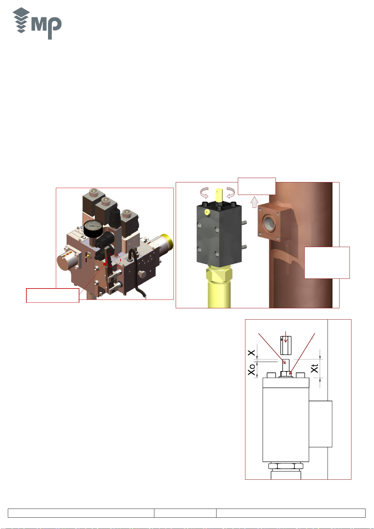
8. Rupture valve
DESCRIPTION
This device consists of a valve that stops the flow of oil when the downward speed of the lift
exceeds a preset value.
The Rupture Valve Test must be done with the FULL LOAD in the lift according to EN 81-2 and EN
81-20 standard.
1. Testing the rupture valve at free fall speed.
- Run the car with full load to the highest floor.
- Fully tighten the screw to test the rupture valve.
- Run the car to the lowest floor.
- The car should descend at a higher speed than the rated speed.
- The pipe rupture valve should trip at 130% of the rated speed.
When this happens, the flow of oil from the cylinder is cut off and the lift stops.
- Fully loosen the testing crew. This will allow the lift to operate normally in descent
but the lift will stop if the oil line breaks.
- Move the lift up to reset the rupture valve.
2. Valve adjustment (if the valve does not trip).
- This operation will only be done if the valve is not adjusted from the factory.
- Run the car to the highest floor.
- Unscrew the locknut.
- Move the car down.
- Tighten the adjusting screw according to the formula Xt=X+Xo, obtained from the
curves of the rupture valve certificate of conformity.
- Screw the locknut
Remove
protective cap
Testing screw of rupture
valve
Protective cap
Adjusting
rod
Lock nut
Turn clockwise the
adjusting rod to
reduce the tripping
flow. Turn
anticlockwise to
increase this value

MP sava3 Hidraulic Power Unit 1 ¼” 1 ½”
V700 - 11/2017
14/40
MTMECMPsava3_700_EN
A Point Upwards deceleration signal.
Place at an S distance from the floor level equal to
B Point Motor disconnected signal.
C Point Downwards deceleration signal.
Place at an S distance from the floor level equal to
D Point YD Electrovalve disconnection signal
Connected
Adjustment
FLOOR
Adjustment
YR
FLOOR
MOTOR
YR
Y- D
4
3
2
5
3
4
A
B
C
D
YD
Connected
For direct starting, motor idle time approx. 0,5 seconds
Change to D
Connect in Y for 2 seconds approx
Y- Dstarting
UPWARDS
DOWNWARDS
YS -
2.2. MP sava3 Valve Block
2.2.1. Description of Valves
2.2.2. Unit operation
1: Pressure relief valve adjustment
2: Upwards acceleration adjustment
3: Upwards/downwards deceleration adjustment
4: Levelling speed adjustment
5: Down speed adjustment
6: Cylinder minimum pressure adjustment.
7: Hand pump relief valve adjustment.
Adjusting screws names
YD Electrovalve
(descent)
+ YE (emergency)
YR Electrovalve
(for speed
change)
Pressure switch
with adjustment
screw
Testing screw
of the rupture
valve
Manual lowering
pushbutton
Hand pump
bleeding
Manometer
protection key
1
6
TO CYLINDER
Starting
Electrovalve YS
(-A3 optional)
Hand
pump
lever
5
4
3
2
7
Magnetic Sensor
Descent Valve
SVD
Magnetic Sensor
Bypass Valve
SVC

MP sava3 Hidraulic Power Unit 1 ¼” 1 ½”
V700 - 11/2017
15/40
MTMECMPsava3_700_EN
VR. Non return valve Screw 1: Pressure relief valve adjustment (maximum pressure)
VA. Starting valve Screw 2: Upwards acceleration adjustment.
VD. Bypass valve Screw 3: Upwards/downwards deceleration adjustment.
VC. Flow regulator valve Screw 4: Levelling speed adjustment.
VB. Descent valve Screw 5: Down speed adjustment.
YR. Electrovalve for changing speed Screw 6: Hand pump relief valve adjustment.
YD. Descent Electrovalve Screw 7: Cylinder minimum pressure adjustment.
YS. Y- Δstarting Electrovalve (optional)
VP. Balancing down pressure switch
VL. Pressure relief valve
CP. Maximum pressure switch (optional)
VM. Manual descent valve
VG. Valve to control the minimum pressure in cylinder
MP sava3 MP Valve Block
Return filter –Shut-off valve
Rupture valve
Hand pump
2.2.3. Hydraulic circuit (Valid for Standard and Y- D configurations)
2.2.4. Valve adjustment
See pages 10-14.
MP sava3 Hidraulic Power Unit 1 ¼” 1 ½”
V700 - 11/2017
16/40
MTMECMPsava3_700_EN
A Point Upwards deceleration signal.
Place at an S distance from the floor level equal to
B Point Disconnected motor signal.
C Point Downwards deceleration signal.
Place at an S distance from the floor level equal to
D Point YD Electrovalve disconnection signal
Connected
Adjustment
FLOOR
Adjustment
YR
FLOOR
MOTOR
YR
YS
4
3
2
5
3
4
A
B
C
D
YD
Connected
Change to D
Connect in Y for 2 seconds approx.
Y- D
Starting
UPWARDS
DOWNWARDS
YS E
lectrovalve will be connected just before getting to the floor
Motor will remain connected for 2 seconds after the lift stops
For direct starting, motor idle time approx. 0,5 seconds
2.3. MP sava3 Valve Block SOFT-STOP
2.3.1. Description of Valves
2.3.2. Unit operation
1: Pressure relief valve adjustment
2: Upwards acceleration adjustment
3: Upwards/downwards acceleration adjustment
4: Levelling speed adjustment
5: Down speed adjustment
6: Cylinder minimum pressure adjustment.
7: Hand pump relief valve adjustment.
Adjusting screw names
YD Electrovalve
(descent)
+ YE (emergency)
YR Electrovalve
(for speed
change)
Pressure switch
with adjustment
screw
Testing screw
of the rupture
valve
Manual lowering
pushbutton
Hand pump
bleeding
Manometer
protection key
1
6
TO CYLINDER
Starting
Electrovalve YS
(-A3 optional)
Hand
pump
lever
5
4
3
2
7
Magnetic Sensor
Descent Valve
SVD
Magnetic Sensor
Bypass Valve
SVC

MP sava3 Hidraulic Power Unit 1 ¼” 1 ½”
V700 - 11/2017
17/40
MTMECMPsava3_700_EN
VR. Non return valve Screw 1: Pressure relief valve adjustment (maximum pressure)
VA. Starting valve Screw 2: Upwards acceleration adjustment.
VD. Bypass valve Screw 3: Upwards/downwards deceleration adjustment.
VC. Flow regulator valve Screw 4: Levelling speed adjustment.
VB. Descent valve Screw 5: Down speed adjustment.
YR. Electrovalve for changing speed Screw 6: Hand pump relief valve adjustment.
YD. Descent electrovalve Screw 7: Cylinder minimum pressure adjustment.
YS. Y- Δstarting electrovalve (optional) Soft-Stop integrated.
VP. Balancing down pressure switch
VL. Pressure relief valve
CP. Maximum pressure switch (optional)
VM. Manual descent valve
VG. Valve to control the minimum pressure in cylinder
Return filter-Shut-off valve
MP sava3 block of valves
Rupture valve
Hand pump
2.3.3. Hydraulic circuit MP sava3 + Soft-Stop
2.3.4. Valve adjustment
See pages 10-14.

MP sava3 Hidraulic Power Unit 1 ¼” 1 ½”
V700 - 11/2017
18/40
MTMECMPsava3_700_EN
COOLER ASSEMBLY
1. Assemble as many hoses as required to enable the
oil input and output from the cooler (see attached table).
2. Insert the IN and OUT hoses of the cooler into the
holes of the tank cover.
3. To assemble the thermostat, see picture here below.
THERMOSTAT
ASSEMBLY DETAIL
The power unit has a dust protection on
the tank identification cover. Remove this
protection before installing the cooler.
REQUIRED ACCESSORIES NOT INCLUDED
INPUT
- SAE 100 Elbow 90º Hydraulic hose
- M G 1”–M G ¾” Connector
- 1” hydraulic joint.
OUTPUT
- SAE 100 Elbow 90º Hydraulic hose
- M G ¾” - M G ¾” Connector
- ¾” Hydraulic joint
ASSEMBLY ON TANK COVER
- 4 T 25-30 Silent-blocks
- 4 DIN 934 M6 nuts
- 4 DIN 7980 Ø6 Grower
- 4 DIN 9021 M6 Washers
.
IMPORTANT:
The oil cooler must not be placed at a height of more than 1100 mm
with regard to the ground where the hydraulic power unit stands.
3 •OIL COOLING DEVICE
3.1 Oil cooling device connections - Hydraulic power unit
INPUT
OUT
MP sava3 Hidraulic Power Unit 1 ¼” 1 ½”
V700 - 11/2017
19/40
MTMECMPsava3_700_EN
ADJUSTING
THERMOSTAT
GENERAL
CONNECTION
THERMOSTAT OPENING 30º C ± 3º C
CLOSING 20º C ± 4º C
POWER 500 W +5/-10%
HEAT FLOW SUPPLIED 2 W/cm2
SUPPLY VOLTAGE 380 V
220 V
THREE-PHASE
COOLER
IMPORTANT: Do not connect the resistance without drowning it into oil
NOTE: The resistance does not work over an oil temperature of 15ºC
3~
TT
TT
TT
R
S
T
2A
2A
3.2. Oil cooler and thermal switch wiring
4 •TANK OIL HEATER
- To make a correct connection between the power unit and the oil heater, see page number 6 of this technical manual.

MP sava3 Hidraulic Power Unit 1 ¼” 1 ½”
V700 - 11/2017
20/40
MTMECMPsava3_700_EN
5•MAINTENANCE
5.1. Cleaning of the reutrn oil filter
5.2. General checks
•Once every 5 to 10 years and depending on the lift general conditions, it is recommended to make a general inspection of all the hydraulic components.
Any worn or old component must be replaced.
•We recommend to filter the oil (the filter should be between 30 and 40 μm) .Clean the tank.
•Change the fitting set (seals and rings) of the cylinder.
•Once the inspection operations have been performed, check all the points as if it was a new installation.
Close the shut-off valve so the power unit and the cylinder are isolated.
Remove the four connection screws of the valve body and open it. Take
out the return filter and clean it correctly. It is very important to set properly
this filter in its housing before the cleaning. Repeat these operations once
per year.
Table of contents
Other MP Industrial Equipment manuals


Popular Industrial Equipment manuals by other brands


ABB
ABB J2007003L301CB quick start guide

Eaton
Eaton NZM1-XDTV Series Instruction leaflet

SCHUNK
SCHUNK TENDO RLA Assembly and operating manual

Regulus
Regulus BIO 55 MIX-BP G75 1F Installation and operation manual

Trooper
Trooper ADVANTAGE TR-100 instruction manual

Phoenix Mecano
Phoenix Mecano LD1000C Assembly instructions


