manuals.online logo
Brands
  1. Home
  2. •
  3. Brands
  4. •
  5. Watlow
  6. •
  7. Controllers
  8. •
  9. Watlow Series 96 User manual

Watlow Series 96 User manual

SERIES 96
Plug and Play
Firmware and
Hardware
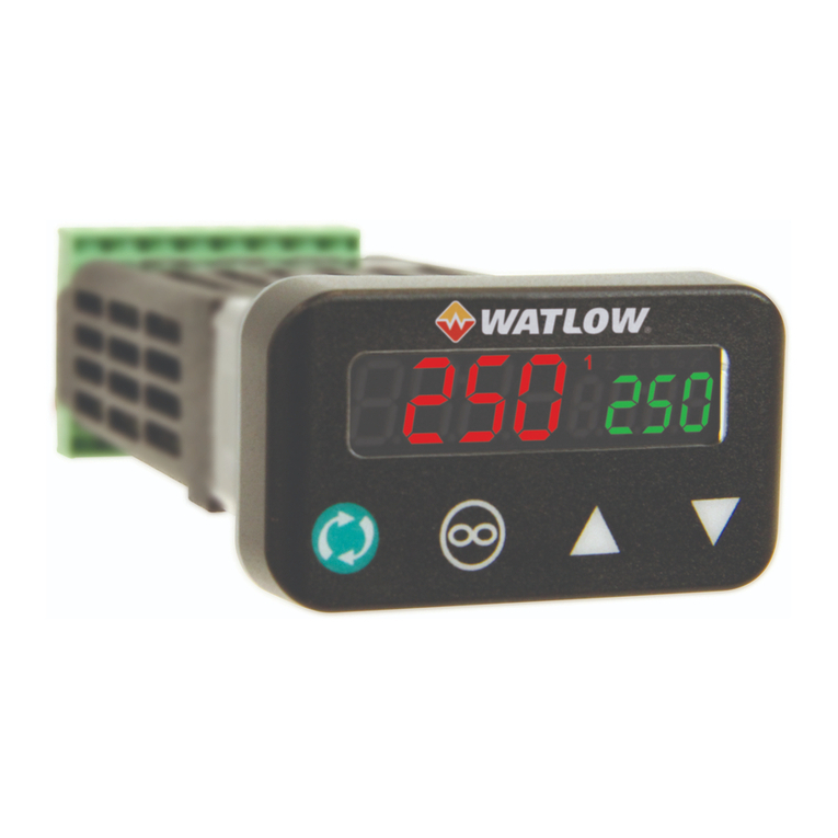
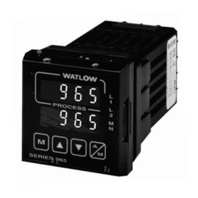
Watlow’s SERIES 96 is a powerful 1⁄16 DIN dual display
controller that offers many advanced functions. This new
controller can be tailored to perform hardware and software
needs with hardware modules that are pluggable and
exchangeable and software menus that may be user
programmed to fit exact application requirements.
With one universal input, a second auxiliary input and four
outputs the SERIES 96 can be programmed to perform:
temperature measurement, input event switching, remote
set point input, heating, boost heating, cooling, alarms,
digital communications, ramp and soak and retransmit.
These features make this controller ideally suited for
applications in markets such as plastics packaging,
semiconductor, food processing and lab equipment.
Set point ramping operations include two files with eight
steps in each. The files can be linked to create a 16-step
profile.
With fast 10Hz sampling, variable time base burst firing
outputs,NEMA 4X front panel and 0.1 percent calibration
accuracy this control can easily handle some of the
toughest application needs.
The SERIES 96 is manufactured by ISO 9001 registered
Watlow Controls and reliably backed by a three-year
warranty.
Features and Benefits
Burst fire
•Increase heater life/better temperature controllability
One input, one auxiliary input, four outputs
•Powerful flexibility at a competitive price
No dipswitches
•Easily configurable from the front panel
Multiple set points
•Flexible automatic control
Pluggable output modules
•Field expandable
Fast 10Hz sampling
•Improved control responsiveness
Programmable menus (Patent pending)
•Can be self-tailored for exact user needs
Open loop break protection
•Indication of thermal loop problem
NEMA 4X (IP65)
•Water and corrosion resistant front panel can be
washed down
16 programmable ramp and soak steps
•Profiles of dynamic production processes can be
programmed into the controller
Automatic tuning
•Easy one step tuning of PID control parameters
© 2007 Watlow Electric Manufacturing Company Printed in the USA on Recycled Paper, 15% Postconsumer Waste
Your Authorized Watlow Distributor Is:
1241 Bundy Boulevard, P.O. Box 5580
Winona, Minnesota 55987-5580 USA
Phone: +1 (507) 454-5300
FAX: +1 (507) 452-4507
Internet: www.watlow.com
E-mail: info@watlow.com
WIN-96-0307
Registered Company
Winona, Minnesota USA
ISO 9001ISO 9001
Specifications
Controller
• Microprocessor-based, user selectable control modes
• Heat and cool auto-tune for control outputs
• Universal input 1, auxiliary input 2, 4 outputs
• Control outputs user selectable as on-off, P, PI, PID
• Input sample period; Single input 10Hz (100 ms), dual
input 5Hz (200 ms) adjustable digital filter
• Display update; 2Hz (500 ms), adjustable digital filter
• Output update; burst, 0.1 to 999.9 seconds
• Input/Output/Communication isolation
• Displayed in °C, °F, or process units
Operator Interface
• Dual 4-digit LED displays: upper 10.2 mm (0.4 in.),
lower 6.2 mm (0.244 in.)
• Advance, Up Arrow, Down Arrow, Infinity tactile keys
Standard Conditions For Specifications
• Ambient temperature 25°C/77°F ±3°C, rated line
voltage, 50 to 60Hz, 0 to 90 percent RH
non-condensing, 15 minute warm-up
Universal Input 1
Thermocouple
• Type J, K, T, N, C (W5), E, Pt 2, D (W3), B, R, S
thermocouple types
• >20MΩinput impedance
• Maximum 20Ωsource resistance
•30µAopen detection bias
RTD
• 2- or 3-wire platinum, 100Ω
• JIS and DIN curves
• Whole or tenth degree indication
• 150µA nominal RTD excitation current
Process
• Range selectable: 0-10VÎ(dc), 0-5VÎ(dc),
1-5VÎ(dc), 0-20mA, 4-20mA,
• Voltage input impedance 20kΩ
• Current input impedance 100Ω
• Minimum current source resistance 1MΩ
• Input resolution 50,000 bits (approx.) at full scale
• mV input impedance 20MΩ
Input 2
Event Input
• Contact or voltage
• 20KΩinput impedance
• Voltage input: event high state 3 to 36VÎ(dc),
event low state 0 to 2VÎ(dc)
•Resistance/contact input: event high state > 23kΩ,
event low state 0 to 2kΩ
Remote Set Point Input: mA or VDC RangeSelectable
• Voltage input impedance 20kΩ
•Current input impedance 100Ω
Output Types
Open Collector/Switched DC
• Open collector configuration:
Maximum voltage 42VÎ(dc)
Maximum current 200mA
Maximum “on” resistance 1.1Ω
Maximum offstate leakage current 100µA
• Switched dc configuration:
Switched dc supply voltage 22 to 28VÎ(dc)
dc supply current limited to 30mA
Solid State Relay
• Optically isolated
• Zero cross switched
• Without contact suppression
• Minimum load current 0.5mA rms
• Maximum current 0.5A rms at 20 to 280VÅ(ac)
• Maximum offstate leakage current 10µA rms
• For resistive loads only, must use RC suppression for
inductive loads
Electromechanical Relay
• Form C contact configuration
•Minimum load current 10mA @ 5VÎ(dc)
•Rated resistiveand inductiveloads: 2A @ 250VÅ(ac)
or 30VÎ(dc) maximum
• Electrical life 100,000 cycles at rated current
• For resistive loads only, must use RC suppression for
inductiveloads
Process
• Range selectable: 0-20mA, 4-20mA, 0-5VÎ(dc),
1-5VÎ(dc), 0-10VÎ(dc)
• Reverse or direct acting
• 0 to 10VÎ(dc) voltage output into 1000Ωminimum load
resistance
•0to 20mA current output into 800Ωmaximum load
resistance
• Resolution:
dc ranges = 2.5mV nominal
mA ranges = 5µA nominal
• Calibration accuracy:
dc ranges = ±15mV
mA ranges = ±30µA
• Temperature stability 100ppm/°C
Retransmit
• Range selectable: 0-20mA, 4-20mA, 0-5VÎ(dc),
1-5VÎ(dc), 0-10VÎ(dc)
• 0 to 10VÎ(dc) voltage output into a 1,000Ωminimum
load resistance
•0to 20mA current output into an 800Ωmaximum load
resistance
• Resolution:
dc ranges = 2.5mV nominal
mA ranges = 5µA nominal
• Calibration accuracy:
dc ranges = ±15mV
mA ranges = ±30µA
• Temperature stability 100ppm/°C
Event &
Universal Remote 232/485
Input Set Point Control Alarm Retransmit Comm
Input 1
Input 2
Output 1
Output 2
Output 3
Output 4
Communications
• EIA/TIA-485 or EIA/TIA-232
• Opto-isolated
• ModbusTM RTU protocol
• 1200, 2400, 4800, 9600, 19200 baud rates
• 32 maximum units can be connected (With additional
485 repeater hardware, up to 247 units may be
connected)
Accuracy
• Input ranges
Type J: 0 to 750°C or 32 to 1382°F
Type K: -200 to 1250°C or -328 to 2282°F
Type T: -200 to 350°C or -328 to 662°F
Type N: 0 to 1250°C or 32 to 2282°F
Type E: -200 to 900°C or -328 to 1470°F
Type C(W5): 0 to 2315°C or 32 to 4200°F
Type D(W3): 0 to 2315°C or 32 to 4200°F
Type Pt 2: 0 to 1393°C or 32 to 2540°F
Type R: 0 to 1450°C or 32 to 2642°F
Type S: 0 to 1450°C or 32 to 2642°F
Type B: 870 to 1700°C or 1598 to 3092°F
DIN: -200 to 800°C or -328 to 1472°F
JIS: -200 to 630°C or -328 to 1166°F
Process: -1999 to 9999 units
Thermocouple Inputs
• Calibration accuracy ±0.1 percent of span ±1°C at
standard conditions
Exceptions:
Type T; 0.12 percent of span for -200°C to -50°C,
Types R and S; 0.15 percent of span for 0°C to 100°C
Types B; 0.24 percent of span for 870°C to 1700°C
• Accuracy span: 540°C/1000°F minimum
• Temperature stability: ±0.1 degree per degree change
in ambient
RTD Inputs
• Calibration accuracy ±0.1 percent of span ±1°C at
standard conditions
• Accuracy span: 540°C/1000°F minimum
• Temperature stability: ±0.05 degree per degree change
in ambient
Process Inputs
• Voltage input ranges
Accuracy ±10mV ±1 LSD at standard conditions
Temperature stability ±100ppm/°C maximum
• Milliamp input ranges
Accuracy ±20µA ±1 LSD at standard conditions
Temperature stability ±100ppm/°C maximum
Agency Approvals
•UL
®916 file number E185611, C-UL®,CE, NEMA 4X
Terminals
• Touch safe
• 22 to 12 AWG
Power
• 100-240Vı(ac/dc) +10 percent, -15 percent; 50/60Hz,
±5 percent
• 24-28Vı(ac/dc) +10 percent, -15 percent; 50/60Hz,
±5 percent
• 7.0VA maximum power consumption
• Data retention upon power failure via nonvolatile
memory
Operating Environment
• 0 to 65°C, 32 to 149°F
• 0 to 90% RH, non-condensing
• Storage temperature: -40 to 85°C, -40 to 185°F
Dimensions
• Width 52 mm (2.05 in.)
• Height 52 mm (2.05 in.)
• Length 107 mm (4.2 in.)
• Depth behind panel surface 98.4 mm (3.875 in.)
• Approximate controller weight 0.2 kg (0.4 lbs)
ModbusTM is a trademark of AEG Schneider Automation.
UL®and C-UL®are registered trademarks of the Underwriter’s
Laboratories, Inc.
Functionality Matrix
Allowable Operating Ranges
Note: These specifications are subject to change without prior notice.
Type J: 1.0 0 to 815°C or 32 to 1500°F
0.1 0.0 to 815.0°C or 32.0 to 999.9°F
Type K: 1.0 -270 to 1370°C or -454 to 2500°F
0.1 -199.9 to 999.9°C or -199.9 to 999.9°F
Type T: 1.0 -270 to 400°C or -454 to 750°F
0.1 -199.9 to 400.0°C or -199.9 to 750.0°F
Type N: 1.0 0 to 1300°C or 32 to 2372°F
0.1 0.0 to 999.9°C or 32.0 to 999.9°F
Type E: 1.0 -270 to 800°C or -454 to 1470°F
0.1 -199.9 to 800.0°C or -199.9 to 999.9°F
Type C: 1.0 0 to 2315°C or 32 to 4200°F
0.1 0.0 to 999.9°C or 32.0 to 999.9°F
Type D: 1.0 0 to 2315°C or 32 to 4200°F
0.1 0.0 to 999.9°C or 32.0 to 999.9°F
Type Pt 2: 1.0 0 to 1395°C or 32 to 2543°F
0.1 0.0 to 999.9°C or 32.0 to 999.9°F
Type R: 1.0 0 to 1760°C or 32 to 3200°F
Type S: 1.0 0 to 1760°C or 32 to 3200°F
Type B: 1.0 0 to 1816°C or 32 to 3300°F
DIN 1.0 -200 to 800°C or -328 to 1472°F
0.1 -199.9 to 800.0°C or -199.9 to 999.9°F
JIS 1.0 -200 to 630°C or -328 to 1166°F
0.1 -199.9 to 630.0°C or -199.9 to 999.9°F
Process -1999 to 9999 units
Ordering Information
SERIES 96 9 6 - -
Microprocessor-based
1⁄16 DIN with universal input 1.
Options include: software, power
supply, input 2, four outputs and
display color
Power Supply
A = 100-240Vı(ac/dc)
B = 24-28Vı(ac/dc)
Input 2
0 = None
1 = Event input & 0-5VÎ(dc)/ 4-20mA
(Remote set point input)
Output 1
C = Switched dc/open collector
D = Electromechanical relay, Form C,
2A, without RC suppression
F = Universal Process, range selectable:
0-20mA, 4-20mA, 0-5VÎ(dc),
1-5VÎ(dc), 0-10VÎ(dc)
K = 0.5A solid state relay without
RC suppression
Output 2
A = None
C = Switched dc output/open collector
D = Electromechanical relay, Form C,
2A, without RC suppression
F = Universal Process, range selectable:
0-20mA, 4-20mA, 0-5VÎ(dc),
1-5VÎ(dc), 0-10VÎ(dc)
K = 0.5A solid state relay without
RC suppression
Output 3
A = None
D = Electromechanical relay, Form C,
2A, without RC suppression
Output 4
A = None
D = Electromechanical relay, Form C,
2A, without RC suppression
M = Universal Retransmit, range selectable: 0-20mA,
4-20mA, 0-5VÎ(dc), 1-5VÎ(dc), 0-10VÎ(dc)
R = EIA/TIA 232 Communications
U = EIA/TIA 485 Communications
Software/Preset Parameters
00 = Standard software (order with Standard Display/Overlay)
AA = Ramping software (order with Ramping Display/Overlay)
XX = Custom software
XX = Preset parameters
Standard Display/Overlay
Upper/Lower
RR = Red/Red display
RG = Red/Green display
GR = Green/Red display
GG = Green/Green display
Ramping Display/Overlay
Upper/Lower
BA = Red/Red display
BB = Red/Green display
BC = Green/Red display
BD = Green/Green display
234%
96
1
52.070 mm
(2.050 in.)
Panel Cutout
44.958 mm x 44.958 mm
(1.77 in. x 1.77 in.)
(2.050 in.)
52.070 mm
4.242 in.
2.330 in.
3.875 in.
0.367 in.
Customer'sFront Panel
(107.747 mm)
(98.425 mm)
(59.182 mm)
(9.322 mm)
To be automatically connected to the nearest North American Technical and Sales Office call:
1-800-WATLOW2
International Technical and Sales Offices: Australia, +61-3-9335-6449 • China, +86-21-3950-9510 • France, +33 (0) 3073-2425 •
Germany, +49 (0) 7253-9400-0 • Italy, +39 (0) 2 458-8841 • Japan, +81-3-3518-6630 • Korea, +82-2-575-9804 • Malaysia, +60-3-7980-7741 •
Mexico, +52 (442) 217-6235 • Shanghai, +86-21-3950-9504 • Singapore, +65-6773-9469 • Spain, +34 91 675 1292 • Sweden, +46 35-27-11-66 •
Taiwan, +886-7-288-5168 • United Kingdom, +44 (0) 115-964-0777

Other manuals for Series 96

1

Other Watlow Controllers manuals

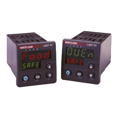
Watlow 97 series User manual

Watlow

Watlow 97 series User manual

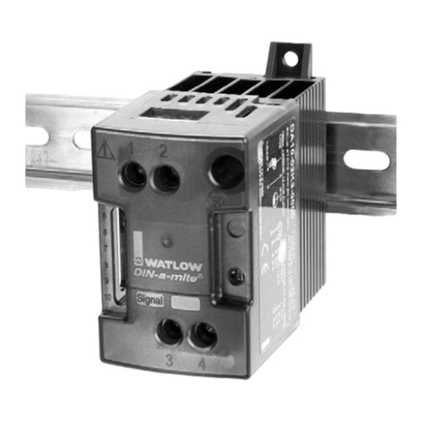
Watlow DIN-A-MITE SCR Power Controller User manual

Watlow

Watlow DIN-A-MITE SCR Power Controller User manual

Watlow F4P Series User manual

Watlow

Watlow F4P Series User manual

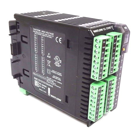
Watlow EZ-ZONE RMC User manual

Watlow

Watlow EZ-ZONE RMC User manual

Watlow DIN-A-MITE Style B User manual

Watlow

Watlow DIN-A-MITE Style B User manual

Watlow MLS-PM User manual

Watlow

Watlow MLS-PM User manual

Watlow PM LEGACY PM3 User manual

Watlow

Watlow PM LEGACY PM3 User manual

Watlow F4T User manual

Watlow

Watlow F4T User manual

Watlow F4P Series User manual

Watlow

Watlow F4P Series User manual

Watlow Integrated Controller  Rev C EZ-ZONE PM User manual

Watlow

Watlow Integrated Controller Rev C EZ-ZONE PM User manual

Watlow ez-zone pm User manual

Watlow

Watlow ez-zone pm User manual

Watlow ez-zone pm User manual

Watlow

Watlow ez-zone pm User manual

Watlow Power Series User manual

Watlow

Watlow Power Series User manual

Watlow PM3 LEGACY User manual

Watlow

Watlow PM3 LEGACY User manual

Watlow EZ-ZONE PM Express User manual

Watlow

Watlow EZ-ZONE PM Express User manual

Watlow PM LEGACY Series User manual

Watlow

Watlow PM LEGACY Series User manual

Watlow ez-zone pm User manual

Watlow

Watlow ez-zone pm User manual

Watlow Ez-Zone PM6 User manual

Watlow

Watlow Ez-Zone PM6 User manual

Watlow Controller Series D8 User manual

Watlow

Watlow Controller Series D8 User manual

Watlow Anafaze PPC-2000 User manual

Watlow

Watlow Anafaze PPC-2000 User manual

Watlow EZ-ZONE PM Express User manual

Watlow

Watlow EZ-ZONE PM Express User manual

Watlow CLS200 User manual

Watlow

Watlow CLS200 User manual

Watlow Controller Series D8 User manual

Watlow

Watlow Controller Series D8 User manual

Watlow 988 series User manual

Watlow

Watlow 988 series User manual

Popular Controllers manuals by other brands

TEL AFA1000/E MK2 Installation & Calibration Guide

TEL

TEL AFA1000/E MK2 Installation & Calibration Guide

Weil-McLain ProtoNode FPC-N34 quick guide setup

Weil-McLain

Weil-McLain ProtoNode FPC-N34 quick guide setup

Rain Evo 1 instructions

Rain

Rain Evo 1 instructions

AFRISO AVD 10 operating instructions

AFRISO

AFRISO AVD 10 operating instructions

Clare Controls CH-OS-L Installation sheet

Clare Controls

Clare Controls CH-OS-L Installation sheet

GeoBox G408 Quick user guide

GeoBox

GeoBox G408 Quick user guide

Siemens ACM-1 installation instructions

Siemens

Siemens ACM-1 installation instructions

JJC WR-100 Instruction

JJC

JJC WR-100 Instruction

Tech Controllers EL480zPID user manual

Tech Controllers

Tech Controllers EL480zPID user manual

RIB DUKE 24V manual

RIB

RIB DUKE 24V manual

RKC INSTRUMENT CB103 INITIAL SETTING MANUAL

RKC INSTRUMENT

RKC INSTRUMENT CB103 INITIAL SETTING MANUAL

ModelCraft 550 operating instructions

ModelCraft

ModelCraft 550 operating instructions

Emerson dixell XW60K Installation and operating instructions

Emerson

Emerson dixell XW60K Installation and operating instructions

Planar DOME Md5/DFP installation guide

Planar

Planar DOME Md5/DFP installation guide

VALPES ER35 Installation and operation manual

VALPES

VALPES ER35 Installation and operation manual

EFIX FC2 user guide

EFIX

EFIX FC2 user guide

Spartan Vortex VX1 user guide

Spartan

Spartan Vortex VX1 user guide

MR TAPCON 250 operating instructions

MR

MR TAPCON 250 operating instructions

manuals.online logo
manuals.online logoBrands
  • About & Mission
  • Contact us
  • Privacy Policy
  • Terms and Conditions

Copyright 2025 Manuals.Online. All Rights Reserved.