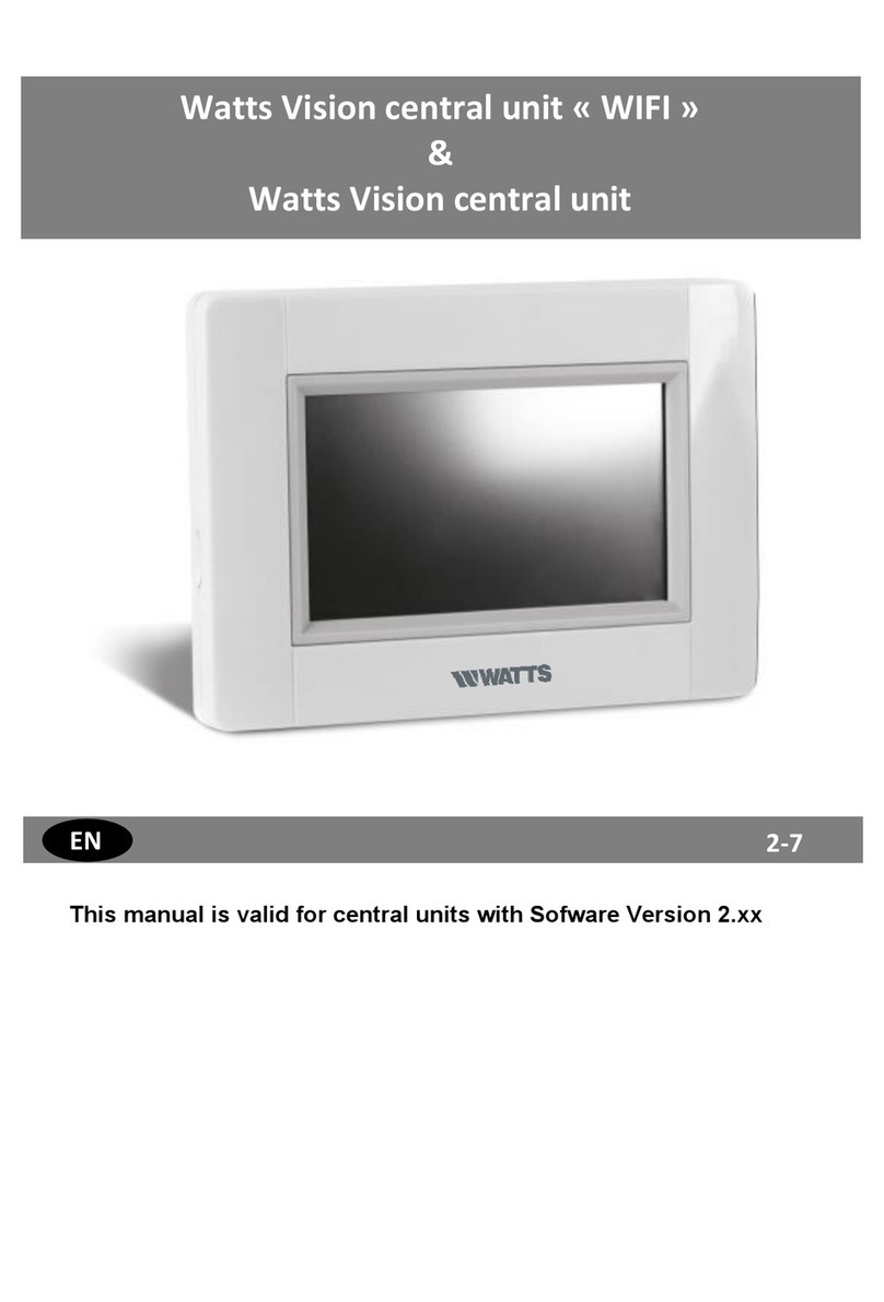
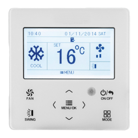
Watts BT-CT02-RF WiFi User manual

1
Central Unit « WIFI »
INSTALLATION AND USER GUIDE 2-10
INSTALLAZIONE E GUIDA UTENTE 11-18
INSTALLATIE- EN GEBRUIKERSHANDLEIDING 19-26
NL
IT
EN
MONTAGE- UND BEDIENUNGSANLEITUNG 27-35
DE
MANUEL UTILISATEUR ET GUIDE D'INSTALLATION 35-44
FR
INSTALLATIONS- OG BRUGERVEJLEDNING 45-53
DA
INSTALLASJONS- OG BRUKSANVISNING 54-62
NO
INSTALLATIONS- OCH ANVÄNDARGUIDE 63-71
SE

2
MAIN CHARACTERISTICS
Touch screen
Interface via internet (WiFi)
Wall mountable with power supply 85-265VAC (50-60) Hz
Table mountable with supplied bracket and mini USB power
supply (0-5V) (sold separately)
Back up Battery operaWtion of 1 hour maximum
RF Communication only with WATTS® Vision® devices (up to
40m internal, extendable with repeater)
Able to manage up to 4 main supply circuits with a dedicated
pump or boiler on each
Multiple heating/cooling devices control.
SD Card slot for updating software
Intuitive menus for devices management
COMPATIBLE DEVICES
Hydraulic panel
heater
Electrical panel
heater
Heating
Cooling
Hydraulic floor
regulation
Electrical floor
regulation
On/Off Lighting
Pilote wire
BT-
FR02
RF
√
√
√
√
√
√
√
√
BT-
WR02
RF
√
√
√
√
√
√
√
BT-
WR02
HC RF
√
√
√
√
BT-
PR02
RF
√
√
√
√
BT-
M6Z02
RF
√
√
√
BT-
HCM02
RF *
√
√
√
BT-
TH02
RF
√
√
BT-A02
RF
BT-D02
RF
BT-
DP02
RF
√
√
√
√
√
√
REPEA
TER
* BT-M6Z02 RF is mandatory
MAXIMUM DEVICES / LIMITATIONS
50 heating/cooling master devices (thermostats) and 50
heating/cooling slave devices (receivers).
25 ON/OFF devices with weekly program with 15 min steps.
50 lighting devices (ON/OFF).
You may have to use a Watts RF repeater if you want to
extend the RF range.
TECHNICAL CHARACTERISTICS
It is an electronic control device
Operating temperature, connected.
Operating temperature, battery
Shipping and storage temperature
-30°C to +40*C
0°C to +40°C
-30°C to +50°C
Electrical Protection
Electrical insulation
IP30
Class II
Temperature precision
0.1°C
Setting Temperature Range
- Comfort
- Reduced
- Anti-freeze
5°C to 30°C in 0.5°C steps
5°C to 30°C in 0.5°C steps
5°C to 10°C
Power Supply
85-265V 50-60 Hz
Radio Frequency
868 MHz, <10mW, Range< 40m
internal, <100m open space
Software version
User interface: Shown on the main
menu V.xx.xx
Wifi communication: Shown on the wifi
menu xx.xx
EU declaration of conformity
Hereby, Watts Electronics declares
that the equipment is in compliance
with the relevant Community
harmonisation legislation
Directive 2001/95/EC on General
Products Safety
Low voltage directive 2006/95/EEC
Radio Equiment Directive
1995/5/EC-2014/53/EU
ROHS Directive 2011/65/EC
The full text of the EU declaration of
conformity is available on
wattswater.eu
SD card
<=16GB (FAT)
WIFI
802.11b –2.4GHz
802.11g –2.4GHz
INSTALLATION SEQUENCE
Congratulations on purchasing your Watts Vision system.
Please follow the set-up sequence below;
1. Install your central unit (see installation –page 37)
and your connected devices (see relevant device
manuals)
2. Personalise your central unit user settings (see User
Settings Menu –pages 3 and 8)
3. Create your house / create and name your rooms (see
House Creation –page 4)
4. Pair your devices to the central controller / allocate
them to the appropriate rooms (see Pair your devices –
page 4) Please charge the central unit for at least one
hour before pairing the devices already mounted
5. Set up remote control of your system via smart-phone /
tablet (see Remote Control - page 5)
6. Program your devices so that they work on a time
schedule (see Heating / Cooling Device Management –
page 5)

3
1 INSTALL YOUR CENTRAL
a- Wall mounting
.
1- Connect the power as described below :
2- Screw the power unit on the wall and connect to power
supply. Note! The tab must be on the top!
3- Put the switch on ON position
4- Mount the Central control on the power unit and slide it on the
bottom to clip it. The Central is ready for operation.
b- Table installation (with optional mini USB cable
–sold seperately)
Connect the central unit with the mini USB cable (5V, 1A) and
then mount the leg support on it and put the switch on ON
position. The central unit is ready for operation.
MAIN SCREEN ICONS
①Date
② Display the time or the ambient T° of the room or zone. Make
your choice by pressing on the central part of the screen
③ Outside sensor temperature
④ Screen lock. Long press toggles between locking / unlocking.
⑤ Error flag –press to access RF, limits, alarms, battery
anomalies.
⑥ The device is working on battery (! only for settings and
pairing).
⑦ Rooms access (if Central is locked - cannot change settings).
⑧ Main menu.
⑨ Holidays mode status.
⑩ Boiler status displayed if connected to the Central.
⑪ Display the ambient temperature in one room
GENERAL PICTOGRAMS
To return to the main screen.
To return to the previous screen.
The buttons with a red point need a long
press (min 5s).
2 ADJUST TIME / USER SETTINGS
Set the time and the date manualy or automatically. If you select
auto, you have to set the time zone (UTC) and the device is
getting the time from internet (WIFI connection is mandatory).
Set your language - see MAIN MENU section
Personalise your screen settings, eg background colour etc
See “User Settings Menu” in MAIN MENU section (page 8) for
further information.
NOT TO BE USED
MAINS POWER SUPPLY 85-265VAC - 50/60HZ
ON/OFF
ON/OFF
CABLE
3
2
4
5
6
7
8
9
10
11
1

4
3 CREATE YOUR HOUSE
long press on
You now need to “create” your house - a list of rooms where the
various devices such as thermostats will be placed.
Create all the rooms and re-name them eg room 1 = Kitchen,
room 2 = Lounge etc
① Scroll over rooms.
④ To create or add a room (zone).
② Current room name
⑤ To change current room (zone)
name.
③ To delete a room
(zone).
4 PAIR YOUR DEVICES TO CENTRAL
Install your devices
Create the room if it doesn’t exist (See section 3)
Go to Radio pairing
- Choose the device type (heating, On/Off Device etc)
- Choose the room
Note: The master (thermostat or BT-M6Z02 RF) must be the
first paired device
- Put the device in pairing mode (refer to device leaflet)
Start the pairing on the Central
- Follow the instructions given by the Central (check on the
device that the pairing is successful, refer to the device leaflet)
- n.b: Automatic pairing time in case of RF communication loss:
10s.
- When you have finished pairing all devices, please check that
the range allows good communication. To do this, adjust the
setpoint temperature on the central and make sure that the
information is received by the thermostat/Receiver.
Check the successful installation
-
- You will have warning in home menu for RF errors
communications. The warning flag should appear for a
maximum of 10mn. It would then disappear if there are no
communication problems. If not, check devices showing RF
errors, try moving them to another place and repeat the
procedure.
HYDRAULIC SYSTEM PAIRING
If your installation has a number of separate hydraulic circuits
containing their own pumps or boilers, you may want to drive
each pump/boiler separately from specific heating receivers or
thermostatic actuator(s). With smartvision you can create and
control up to 4 hydraulic circuits. Each of the circuits will have an
RF remote circuit receiver linked to it that will activate the
intended pump and boiler. If at least one heating receiver or
thermostatic actuator on the circuit has a demand, the linked
circuit receiver will operate and activate the pump (and / or
boiler).
First step: define on which circuit a device belongs to
With the plan of your installation, define which devices are on
“circuit 1”. Then, using the Central controller, pair and configure
all these devices on circuit 1.
To do this, in the main screen press , enter a zone (room)
that is on circuit 1, then press and select one device of
circuit 1 and press 5 seconds. Now you have entered the
configuration menu of the device. Choose menu “HC”, now you
have two options, Electrical or Hydraulic, select Hyraulic and
then press on button . You can now select the circuit, that
the device will act on, eg circuit 1.
Proceed like this for every heating/cooling device of this circuit.
Once all elements of circuit 1 are set, do the same for the other
hydraulic circuits.
Second step: control the circuits
For each circuit, you can link a circuit receiver to drive the
pump/boiler of the circuit. This can be done for example by BT-
WR02 RF.
From the main screen, press then press . On the list
box, choose “Radio pairing”, then “Circuit”. Select the number of
the circuit, eg circuit 1. Put the element to link (BT WR02 RF) in
link mode, then start process by pressing .
Do the same for the other circuit, if you have more.
Heat and Cool installations
If your installation includes both heating and cooling functions,
you can switch either from Heat to Cool manually or
automatically:
- If you have a BT HCM02 RF in your installation set as
“Master” (refer to Manual instruction of the device) then all
is automatic you don’t have to do anything
- For all other cases, you have to do the switch manually:
from main screen press then and go in “H&C”.
There you will have the choice netween “Heating Only”
“Cooling Only” or “Manual Reversible”. With this last option,
you create a shortcut in the main menu (icon 4) where you
can easily change Heat/Cool mode.
Notes:
- In Cooling Mode, Reduced mode and Antifreeze
mode are inactive: icon is displayed instead
of or .
- In the thermostat, user can configure the parameter “Cold”
that allows the zone to do Cooling or not. If it is set to “No”,
then if the mode of the zone is Cooling then the zone won’t
make Cooling.
1
1
2
3
4
5

5
INSTALLATION TYPES
(HEATING/COOLING)
Type 1 :
In this configuration:
Pair first the thermostat (master) with the Central before
pairing the other devices (configured as heating devices).
The actuators regulate on thermostat temperature.
Type 2 :
In this configuration:
Pair first the thermostat (master - configured as a heating
device) with the Central before pairing the other devices.
The other devices regulate on thermostat temperature.
Warning! In this installation type, the BT (MASTER) must be in
regulation Air mode (not floor or Air + Floor)
Type 3 :
In this configuration (no thermostat);
BT-TH configured as heating device.
BT-PR, BT-FR, BT-WR can be configured as an On/Off or
lighting devices.
Type 4 :
In this configuration:
Each thermostat is first paired with the appropriate UFH1 and
then the UFH1(s) are paired with the Central
During the pairing, the Central automatically creates rooms
according to the number of thermostats (rooms) of UFHs.
5 SET UP REMOTE CONTROL
1 Connect the central unit to your WiFi network: To do this;
Go to installation menu (long press)
Choose WiFi settings
Choose Research Networks (searches for your wifi)
Choose your WiFi from the list
Enter your regular WiFi password
Observe unit counting down from 120 to zero
Make sure that the central is now connected to the WiFi network
with an IP address (WiFi status should read 1/2)
Press the home key to go back to front screen
If after several attempts, connection is unsuccessful, connect the
central unit to WiFi manually (see WiFi settings page 9).
2 Download the app to your device;
For PC; click on dedicated link available on www.wattswater.eu
homepage
For Smartphone; download WATTS® Vision™ application from
App store or Google Play.
3 Create an Account
Enter your details and select language.
Select “Validate” (email will be sent to you with link).
Go to your email and click on the link.
Go back to your App account and follow the on screen
instructions.
Request a pairing code to link your central unit. The pairing
code (valid 24h) is sent to your email inbox.
In the WiFi status menu of the central unit, enter the
pairing code (internet access password)..
Your central unit should appear after a few minutes in the
application or the web page. Click the refresh button if
necessary. WiFi status should read 2 /2.
Please note! It may take up to a few hours to display all rooms
and devices in the application. You can then operate your central
unit from anywhere.
Watts is not responsible for the correct operation of the
connected devices, and potential damage caused by malfunction
or improper use of the connected devices and appliances.
6 HEATING/COOLING DEVICES
MANAGEMENT & PROGRAMMING
Press on in the main screen and after selecting the room,
press on
7
13
3
2
4
5
6
7
8
9
10
11
1
2
7
12

6
① Device type choice (heating/cooling, lighting, On/Off). These
buttons are only displayed if one device type is installed in the room
(colored if active).
② Room changing.
③ Current mode, press on this icon to enter in the menu where
you can change the current operating mode.
④ Ambient temperature or setting temperature (setpoint) or
humidity after one press on 10.
⑤ Heating/cooling indicator (animated if demand).
⑥ Information about the heating/cooling devices installed in the
room.
⑦ Set the current setpoint (deactivated if the screen is locked).
⑧ Current room name.
⑨ Quick access to the desired room.
⑩ To display either the ambient or setting temperature or Humidity
in 4.
⑪ Pilot wire status.
⑫Floor temperature if floor regulation.
⑬Only displayed if the screen is locked.
Press on « 3 » in the previous menu to access this modes menu:
Comfort Mode : Set the room in comfort mode. If it
remains active, the comfort temperature will be followed all the
time.
Reduced Mode : Set the room in reduced mode. If it
remains active, the reduced temperature will be followed all the
time.
Timer or Boost Mode : Temporary derogation. Set the
timer duration (days, hours, minutes) by pressing on
button, then validate and set the desired temperature on main
screen.
Anti freeze Mode : Use this mode to put your room in
anti-freeze mode (the temperature is set in the Installation menu)
OFF Mode : To switch OFF the device. Be careful! In this
mode, your installation can freeze!
PROGRAMMING YOUR DEVICES
Auto Mode : In this mode, the room temperature will
follow the program you have chosen. You can choose between
existing programs or you can create a new one that you can
modify as you want.
Press on to select between :
a- Select: To select an existing program.
b- Create: To create a new program.
Select the days for which you want the same program (in the
example, Wednesday, Thursday and Friday).
Use the Comfort button to select the hourly ranges during
which the comfort temperature will be followed (brown range)
and the reduced button to select the hourly ranges during
which the reduced temperature will be followed (blue range).
Use the arrows and to put the cursor on the desired
hours.
Validate the program; the validated days are then highlighted in
green (on this example: Monday and Tuesday).
The days that are not programmed are displayed in red.
c- Edit: To view and modify an existing program
d- Information: to view the current program
P1: morning, evening & weekend.
P2: morning, midday, evening & weekend.
P3: day & weekend.
P4: evening & weekend.
P5: morning, evening (bathroom).
a
b
d
a
b
c
d

7
LIGHTING DEVICES MANAGEMENT
Press on in the main screen and press on
① Device type choice (heating/cooling, lighting, On/Off). These
buttons are only displayed if one device type is installed in the
room (colored if active).
②Room changing.
③Information about the lighting devices installed in the room.
④Indicates both the current lighting device number / the number
of lighting devices in the room.
⑤Indicates the lighting status. A press on it switches the lighting
status.
⑥General management for all lighting in the room.
⑦Current room.
⑧Quick access to the desired room.
⑨Only displayed if the number of devices is upper than 1; used
to select the devices in the room.
⑩Only displayed if the screen is locked.
Please note that the lighting functionality does not support
programs. If you want to program the lighting devices, please set
the devices as ON/OFF.
ON/OFF DEVICES MANAGEMENT
Press on in the main screen and on
①Device type choice (heating/cooling, lighting, On/Off). These
buttons are only displayed if one device type is installed in the
room (colored if active).
②Room changing.
③Information about the device.
④Indicates both the number of the current device / number of
devices in the room.
⑤Indicates the ON/OFF status. A press on it switches the
status of the device.
⑥General management for all the ON/OFF devices in the
room.
⑦Current room.
⑧Quick access to the desired room.
⑨Only displayed if the number of devices is upper than 1; used
to select the devices in the room.
⑩Long press to switch between auto mode and normal mode
(colored if active).
⑪Displayed only if the device is in Auto mode, press to access
and edit the device program.
⑫Only displayed if the screen is locked.
3
2
4
5
6
7
8
9
10
11
1
3
4
5
6
7
8
9
10
11
2
1
2
2
3
9
12

8
MAIN MENU
Press to go to main menu
①Energy consumption statistics menu.
②Language (the flag of the current language is
displayed).
8 languages are proposed. If you want to select another
language, you need to insert the software (available on
www.wattswater.eu.) on a microSD then select 8 new
languages.
③General commands menu.
Use this menu to put all the same devices type in the same
operating mode.
To select the
heating/cooling devices
mode for all the
installation.
To select the ON/OFF
devices mode for all the
installation
To select the lighting
devices mode for all the
installation.
To validate the selections.
④Heating/cooling mode management menu.
See section “Heating and cooling control”
⑤User settings menu.
In this menu, you can set:
- Time, Date (Manual, Automatic).
- Time zone (UTC) if the device is in automatic time update
mode
- Time and date if the device is in manual time update mode
- Summer-Winter (Manual, Automatic).
- Temperature unit (°C, °F).
- Background Color.
- Buttons color
- Backlight
- Screen saver (Enabled, Disabled).
- Default screen (Home, Clock, Disabled)
- Screen cleaner.
- Factory default user (interface).
⑥WIFI menu.
Reading button (refreshment).
The Internet Access password allows to link your central unit to
your Internet account (See below) for a remote control of your
system through the Internet or Smart Phone.
n.b.: At first use or software update, wait for some time until the
green State icon is active.
⑦Holidays menu.
- To set the departure/return dates and time.
- Use < or > to select year/month/day, hour & minute.
- Set and validate the operating mode of the devices in holiday
mode. (Same menu then general commands menu).
⑧Installation menu (long press 3-4 s)
1
2
4
5
6
7
8
A
B
C
D
E
3
F
G
H
I
b
a
d
c
a
b
c
d

9
House creation.
See house creation section.
Radio pairing.
See radio pairing section.
Delete a device:
Select device type and then the device.
Delete all devices:
All devices installed in the system will be deleted (rooms
will be maintained).
Identify a device
To identify a device of the installation, go to Menu,then “Identify
a Device”
a- To put the menu in reception mode.
b- To access to the device parameters.
Process:
- Press on ‘a’ to make the Central listening
- Press on the device receiver and wait a few seconds until radio
communication frame is transmitted.
Note: ID-number is displayed on the screen, please repeat to be
sure to have the same ID.
- Long press on to change device parameters (name,
power …).
Antifreeze setpoint:
You can set the antifreeze setpoint as reference for the whole
installation. Heating setting:
You can fix setpoint limitations (min/max) per zone and the offset
assigned to devices working in floor sensor regulation
Heating/cooling settings:
You can set the installation in heating mode, in cooling mode or
in manual mode. If you set the device in manual mode, the
icon appears on the main menu.
WIFI settings:
To set the WIFI configurations (SSID/Protected Access Key
Type/ Password). You can do it manually or scan the active
networks.
Configuration requesting a registration on a web page is not
supported.
WIFI Status:
0/2 : Central unit not connected to the wifi router and server
1/2 : Central unit connected to the Wifi router
2/2: Central unit connected to the wifi router and to the server
(Pairing of the central to an account is required)
n.b.: The connection to Internet is recommended with Certified
WiFi routers (http://www.wi-fi.org/certification).
n.b.: Automatic pairing time to WiFi router with WEP key: 3-4
min, with WPA2 key: 1 min.
n.b.: For the network scan, Repeat at least twice the operation if
your desired WiFi network is not displayed. If your desired WiFi
network is still not displayed, enter the WiFi settings manually
General factory default:
To reset the system with the factory values, but the software
version will remain the same.
Update Firmware:
To update the software, with the SD-card. The system is
qualified to work with SD-cards less than or equal to 16GB.
Select
to proceed.
Please wait the end of the update procedure (The Wifi icon
should be available for the Wifi central unit) before removing the
microSD from the central unit.
The SW and the procedure to update the central unit is available
on www.wattswater.eu.
Cloning:
The menu allows to transfert a configuration from central 1 to
central 2. If you change the central, you do not have to
reconfigure your system.
Put update.bin file on SD card (Special software for cloning
available on www.wattswater.eu.
Insert the SD card in central 1 and make an update firmware
Insert the same SD card in central 2 and launch the cloning.
After the cloning, you need to reconfigure the Wifi and the
langage.
Displosal and recycling information
Correct disposal of this product. This marking shown on
the products indicates that it should not be disposed with other
household waste at the end of its worlking life.
Disposal of waste batteries: This product contain batteries. If so,
use the separate collection for battery recycling. Do not ut them
with other household waste.
This device is suitable for use by children 8 years of age or older,
and for persons with reduced physical, sensory or mental
abilities or lack of experience or knowledge, if they are properly
supervised, or if instructions on the safe use of the device have
been given to them and the risks involved have been addressed.
Children should not play with the device. Cleaning and
maintenance by the user should not be performed by unattended
children.
J
K
L
b
A
B
D
E
F
G
H
I
J
K
L
C
a

10
Contact Us
Watts Electronics S.A.S
B.P. N°10 - Z.A. des Tourettes
43800 ROSIERES
France
T : +33(0) 471 57 40 49
F : +33(0) 471 57 40 90
www.wattsindustries.com

11
CARATTERISTICHE PRINCIPALI
Touch screen.
Interfaccia via internet (WiFi).
Può essere posizionato ad incasso con la staffa in dotazione
ed alimentazione elettrica 85-265VAC (50-60Hz).
Può essere posizionato sul tavolo con la staffa in dotazione e
un alimentatore USB (0-5V) venduto separatamente).
Funzionamento a batteria per una durata massima di 1 ora.
Comunicazione RF solo con dispositivi WATTS® Vision® (fino
a 40m interno, ampliabile con ripetitore).
Può gestire fino a 4 circuiti principali con pompa o caldaia
dedicata ognuno.
Controllo di più dispositivi di riscaldamento/raffreddamento.
Porta Micro SD Card per aggiornamento software.
Menu intuitivi per la gestione dei dispositivi.
COMPATIBILITA’ DISPOSITIVI
* BT-M6Z02 RF è obbligatorio
LIMITAZIONI / N. MASSIMO DISPOSITIVI
50 dispositivi di riscaldamento / raffreddamento MASTER
(termostati) e 50 dispositivi SLAVE (ricevitori).
25 dispositivi di accensione/spegnimento con programma
settimanale basato su incrementi di 15 minuti.
50 dispositivi di illuminazione (ON/OFF).
Per ampliare l'intervallo RF potrebbe essere necessario
utilizzare un ripetitore RF Watts.
CARATTERISTICHE TECNICHE
Temperatura d'esercizio, con
alimentazione elettrica
Temperatura d'esercizio, a
batteria
Temperatura di spedizione e
stoccaggio
-30°C to +40*C
0°C to +40°C
-30°C to +50°C
Protezione elettrica
Isolamento elettrico
IP30
Classe II
Precisione della temperatura
0.1°C
Intervallo della temperatura
impostata
- Comfort
- Ridotta
- Antigelo
5°÷30°C - incrementi di 0.5°C
5°÷30°C - incrementi di 0.5°C
5°÷10°C
Alimentazione elettrica
85-265VAC 50-60Hz
Radiofrequenza
868 MHz, <10mW,
Distanza < 40m interno,
< 100m campo aperto
Versione Software
Interfaccia utente: mostrata nel
menu principale V.xx.xx
Comunicazione WiFi: mostrata
nel menu WiFi xx.xx
Direttive CE:
Il prodotto è stato progettato
in conformità alle Direttive
Europee
R&TTE 1999/5/EC
LVD 2006/95/EC
EMC 2004/108/EC
RoHS 2011/65/EU
Micro SD card
<=16GB (FAT)
WIFI
802.11b –2.4GHz
802.11g –2.4GHz
SEQUENZA D’INSTALLAZIONE
Congratulazioni per aver acquistato questo Sistema WATTS®
Vision®. Seguire la seguente sequenza di istruzioni
d’installazione:
1. Installare l’unità centrale (vedi Installazione –pag. 12)
ed i dispositivi ad esso collegati (far riferimento ai rispettivi
manuali d’uso).
2. Personalizzare le impostazioni utente dell’unità (vedi
menù Impostazioni Utente –pagg.20 e 17).
3. Creare la propria casa / creare e nominare le proprie
stanze (vedi Crezione di una Casa –pag.13).
4. Associare i dispositivi all’unità centrale / posizionarli
nelle stanze appropriate (vedi Associazione Dispositivi –
pag.13). Caricare la centralina per almeno un'ora
prima di associare i dispositivi già montati.
5. Impostare il controllo remoto del sistema via
smartphone / tablet (vedi Controllo Remoto –pag.14).
6. Programmare i dispositivi in modo che lavorino ad un
orario stabilito (vedi Gestione dei dispositivi di
Riscadamento / Raffreddamento –pagg.14 e 15).
Riscaldamento a
pannelli idraulici
Riscaldamento a
pannelli elettrici
Riscaldamento
Raffreddamento
Regolazione dell'impianto
idraulico a pavimento
Regolazione dell'impianto
elettrico a pavimento
On/Off dispositivi di
illuminazione
Filo Pilota
BT-FR02 RF
√
√
√
√
√
√
√
√
BT-WR02
RF
√
√
√
√
√
√
√
BT-WR02
HC RF
√
√
√
√
BT-PR02 RF
√
√
√
√
BT-M6Z02
RF
√
√
√
BT-HCM02
RF *
√
√
√
BT-TH02 RF
√
√
BT-A02 RF
BT-D02 RF
BT-DP02 RF
√
√
√
√
√
√
RIPETITORE

12
1 INSTALLAZIONE
c- Montaggio a parete
5- Collegare l'alimentazione come descritto di seguito:
6- Collegare alla rete elettrica ed avvitare l'unità di alimentazione
alla parete. Attenzione! La linguetta deve trovarsi in alto!
7- Collocare l'interruttore in posizione ON:
8- Montare la centralina sull'unità di alimentazione e farla
scorrere sulla parte inferiore per fissarla con una clip. La
centralina è pronta per essere messa in funzione.
d- Installazione su tavolo (con alimentatore e cavo
USB –venduto separatamente)
Collegare la centralina con il cavo (5 V, 1 A), quindi montare il
supporto e collocare l'interruttore in posizione ON. La centralina
è pronta per essere messa in funzione.
SCHERMATA PRINCIPALE - ICONE
① Data
② Mostra l'ora o la temperatura ambientale del locale o della
zona. Per scegliere premere sulla parte centrale dello schermo.
③ Sensore di temperatura esterna.
④ Blocco schermo –Premere a lungo per blocco/sblocco
schermo.
⑤ Segnalazione Errore di sistema –premere per accedere
all’elenco anomalie (RF, limiti, allarmi, problemi alle batterie…).
⑥ L’unità sta funzionando a batteria (Uso consigliato per
impostazioni ed associazione dispositivi –durata batterie ±1h).
⑦ Accesso ai locali (se la Centrale è bloccata non è possibile
modificare le impostazioni).
⑧Menù Principale.
⑨ Stato modalità Vacanza.
⑩ Stato della caldaia, visualizzato se collegata alla centralina.
⑪ Visualizza la termperatura ambientale in una stanza.
PITTOGRAMMI GENERALI
Per tornare alla schermata principale.
Per tornare alla schermata precedente.
I pulsanti con un punto rosso devono
essere premuti a lungo (almeno 5 s).
2 REGOLAZIONE ORARIO /
IMPOSTAZIONI UTENTE
Impostare la modalità di aggiornamento dell’ora, manuale o
automatico. Se si seleziona la modalità AUTO è necessario
impostare la zona fascia oraria (UTC), l’unità rileverà l’ora
corrente da internet (sarò necessaria una connessione WIFI).
Impostare la lingua - vedi all’interno del Menu Principale (pag.17)
Personalizzre lo schermo, ad esempio colore sfondo, etc.
Per maggiori informazioni far riferimento a “Menu Paremetri
Utente” all’interno del Menu Principale (pag.17).
DA NON UTILIZZARE
ALIMENTAZIONE ELETTRICA 85-265VAC - 50/60HZ
ON/OFF
ON/OFF
CAVO
3
2
4
5
6
7
8
9
10
11
1

13
3 CREAZIONE DI UNA CASA
pressione lunga
È necessario “creare” la propria casa – una lista di stanze dove
saranno installati i vari dispositivi, ad esempio i termostati.
Creare tutte le stanze e rinominarle, ad esempio stanza 1 =
Cucina, stanza 2 = Soggiorno, etc.
① Scorrere le stanze
④ Per creare/aggiungere
stanze (zone)
② Nome della stanza corrente
⑤ Per cambiare nome alla
stanza (zona) corrente
③ Eliminare una stanza (zona)
4 ASSOCIAZIONE DISPOSITIVI
Installare i dispositive
Creare la stanza se ancora non esiste (vedi sez. 3)
Spostarsi su Associazione Radio (Radio pairing)
- Scegliere il tipo di dispositivo (riscaldamento, On/Off, etc)
- Scegliere la stanza.
Nota: il master (termostato o BT-M+Z02 RF) deve essere il
primo dispositivo associato.
- Mettere il dispositivo in modalità Associazione (fare
riferimento al foglio di istruzioni del dispositivo).
Avviare l'associazione sulla centralina .
- Seguire le istruzioni fornite dalla centralina. Controllare sul
dispositivo che l'associazione avvenga con successo (fare
riferimento al foglio di istruzioni del dispositivo).
- N.B: tempo di associazione automatica in caso di perdita di
comunicazione RF: 10 s.
- Al termine dell’associazione ed installazione dei dispositivi
nella loro posizione finale, accertarsi che tra di loro vi sia una
buona comunicazione RF. Modificare il setpoint di temperura
sulla centralina ed accertarsi che il termostato e il ricevitore
ricevano le informazioni.
Controllare che l'installazione sia stata effettuata
con successo
-
- Un simbolo di allarme appare sul menu principale nel
caso di errata comunicazione RF . La segnalazione dovrebbe
sparire da sola entro 10 min, ed il segnale RF ristabilito. In
caso contrario controllare i dispositivi che ancora presentano
errore RF, spostarli e ripetere la procedura.
ASSOCIAZIONE IMPIANTI IDRAULICI
Se l'impianto ha elementi idraulici, potrebbe essere necessario
comandare pompe o caldaie. Con Smartvision è possibile
comandare fino a quattro circuiti idraulici. E, per ognuno di essi,
è possibile collegare un dispositivo remoto RF. È facile: se
almeno un elemento del circuito ha un fabbisogno di
riscaldamento/raffreddamento, l'elemento azionerà il circuito e
farà fluire l'acqua.
1° passaggio: definire a quale circuito l'elemento appartiene
Con il progetto dell'impianto, definire quali elementi sono sul
"circuito 1". Quindi configurare su Smartvision tutti gli elementi
(dispositivi di riscaldamento/raffreddamento) sul circuito 1.
Per farlo, premere , nella schermata principale, entrare in
una zona sul circuito 1, quindi premere e selezionare un
dispositivo del circuito 1 e premere per 5 secondi. In
questo modo si entra nel menu di configurazione del dispositivo.
Scegliere il menu "HC"; sono disponibili due opzioni: Elettrico o
Idraulico. Selezionare Idraulico e quindi premere il pulsante
. Ora si può selezionare il circuito su cui agirà il dispositivo.
Procedere in questo modo per ogni dispositivo di
riscaldamento/raffreddamento di questo circuito.
Una volta impostati tutti gli elementi del circuito 1, ripetere la
stessa procedura per gli altri circuiti idraulici.
2° passaggio: controllare i circuiti.
Per ogni circuito è possibile collegare un elemento per
comandare la pompa/caldaia del circuito. Questo può essere
fatto, per esempio, tramite BT-WR02 RF.
Dalla schermata principale, premere e poi . Sulla
casella dell'elenco, scegliere "Radio pairing" (Associazione
radio) e poi "Circuit" (Circuito). Selezionare il numero del circuito,
mettere l'elemento da collegare (BT WR02 RF) in modalità
Collegamento, quindi avviare il processo premendo .
Ripetere la stessa procedura per altri circuiti, se presenti.
Impianti di riscaldamento e raffreddamento
Se l'impianto è predisposto anche per il raffreddamento, è
possibile passare automaticamente o manualmente da
Riscaldamento a Raffreddamento:
- Se si ha un BT HCM02 RF nell'impianto, impostarlo come
"Master" (fare riferimento al manuale del dispositivo). La
procedura è completamente automatica, pertanto non
occorre fare niente.
- Per tutti gli altri casi, effettuare l'accensione manualmente:
dalla schermata principale premere quindi e
andare su "H&C". A questo punto occorre scegliere tra
"Heating Only" (solo riscaldamento), "Cooling only" (solo
raffreddamento) o "Manual Reversible" (reversibile
manualmente). Quest'ultima opzione permette di creare un
collegamento nel menu principale (icona 4) in cui è
possibile modificare facilmente la modalità
Riscaldamento/Raffreddamento.
Note: - Nella modalità Raffreddamento, le modalità
Temperatura ridotta e Antigelo sono inattive:
appare l'icona invece di o .
- Nel termostato, l'utente può configurare il
parametro "Cold" (Freddo) che permette di
raffreddare o meno la zona. Se si imposta su "No",
se la modalità della zona è Raffreddamento, la
zona non verrà raffreddata.
1
1
2
3
4
5

14
TIPI DI IMPIANTI
(RISCALDAMENTO/RAFFREDDAMENTO)
Tipo 1 :
In questa configurazione :
Associare prima il termostato (master - configurato come
dispositivo di riscaldamento) con la centralina prima di
associare gli altri dispositivi.
Gli attuatori regolano la temperatura del termostato.
Tipo 2 :
In questa configurazione :
Associare prima il termostato (master - configurato come
dispositivo di riscaldamento) con la centralina prima di
associare gli altri dispositivi.
Gli altri dispositivi regolano la temperatura sul termostato.
Attenzione! In questo tipo di impianto, il BT (MASTER) deve
essere nella modalità di regolazione Aria (non Pavimento o Aria
+ Pavimento).
Tipo 3 :
In questa configurazione (senza termostato) :
BT-TH configurato come dispositivo di riscaldamento;
BT-PR, BT-FR, BT-WR possono essere configurati come
dispositivi On/Off o di illuminazione.
Tipo 4 :
In questa configurazione :
Ogni dispositivo UFH 1 è associato alla centralina e i
termostati sono associati all'UFH
Durante l'associazione, la centralina crea automaticamente le
stanze in base al numero dei termostato (stanze) dei
dispositivi UFH. Alle stanze vengono assegnati nomi
predefiniti. È possibile modificarlo nel menu "Creazione di una
casa". È possibile identificarle con diverse temperature
impostate.
5 CONTROLLO REMOTO
1 Connettere l’unità centrale alla rete WiFi: Per farlo:
Entrare nel menu di installazione (pressione lunga);
Selezionare Parametri WiFi;
Selezionare Ricerca Reti (cercare la propria rete WiFi);
Selezionare la propria rete WiFi dalla lista che appare;
Inserire la propria password WiFi;
Osservare il conteggio alla rovescia dell'unità da 120 a zero;
Accertarsi che la centralina sia collegata alla rete WiFi con un
indirizzo IP (stato WiFi dovrebbe essere 1/2);
Premere il pulsante Home per tornare alla schermata principale.
Se dopo diversi tentativi non si riesce a stabilire una
connessione, connettere la centralina alla propria rete WiFi
manualmente (vedi Impostazioni WiFi –pag.18).
2 Scaricare l’applicazione sul proprio dispositivo;
Per utilizzo con PC; cliccare sul link dedicato su homepage di
www.wattswater.eu
Per Smartphone; scaricare l’applicazione WATTS® Vision™
dall’App store o da Google Play.
3 Creare un Account
Inserire le proprie informazioni e selzionare la lingua;
Selezionare “Validate” (il Sistema invierà un’email con link);
Confermare l'e-mail ricevuta;
Tornare sul profilo dell’applicazione e seguire le istruzioni date;
Richiedere un codice di associazione per collegare la centralina
al proprio account.
Il codice di associazione (valido 24h) viene inviato alla propria
casella di posta.
Inserire il codice d’associazione ricevuto nel menu dello stato
WiFi della centralina .
Dopo qualche minuto dovrebbe comparire la propria centralina
nell'applicazione o nella pagina web. Premere il pulsante di
aggiornamento se necessario. Stato WiFi dovrebbe essere 2/2.
ATTENZIONE! Potrebbero essere necessarie alcune ore per
visualizzare tutte le stanze ed i dispositivi nell'applicazione. Sarà
quindi possibile comandare la centralina da qualunque luogo.
Watts non è responsabile del corretto funzionamento dei
dispositivi collegati e dei danni potenziali causati da
malfunzionamento o uso improprio dei dispositivi e degli
apparecchi collegati.
6 GESTIONE DEI DISPOSITIVI DI
RISCALDAMENTO/RAFFREDDAMENTO
Premere sulla schermata principale e, dopo aver
selezionato la stanza, premere su
7
13
3
2
4
5
6
7
8
9
10
11
1
2
7
12

15
① Scelta del tipo di dispositivo (riscaldamento/raffreddamento,
illuminazione, On/Off). Questi pulsanti appaiono se nella stanza
è installato un dispositivo di questo tipo (se attivo è colorato).
② Modifica della stanza.
③ Modalità attuale. Premere su quest'icona per accedere al
menu dove è possibile modificare la modalità operativa attuale.
④ Temperatura ambientale o impostazione della temperatura
(punto di regolazione) o umidità dopo aver premuto una volta sul
pulsante 10.
⑤ Indicatore richiesta di riscaldamento/raffreddamento (l’icona
è animata quando il dispositivo attiva la richiesta).
⑥ Informazioni sui dispositivi di riscaldamento/raffreddamento
installati nella stanza.
⑦ Impostare il punto di regolazione attuale (disattivato se lo
schermo è bloccato).
⑧ Nome attuale della stanza.
⑨ Accesso rapido alla stanza desiderata.
⑩ Per mostrare la temperatura ambientale, la temperatura
impostata o l'umidità in 4.
⑪ Stato filo pilota.
⑫ Temperatura a pavimento con regolazione a pavimento.
⑬ Appare solo se lo schermo è bloccato.
Premere su "3" nel menu precedente per accedere a questo
menu di modalità:
Modalità Comfort : Impostare la stanza in modalità
Comfort. Se rimane attiva, la temperatura di comfort verrà
seguita sempre.
Modalità Temperatura ridotta (Reduced) : Impostare la
stanza in modalità Temperatura ridotta. Se rimane attiva, la
temperatura ridotta verrà seguita sempre.
Modalità Timer or Boost : Deviazione temporanea.
Impostare il timer (giorni,ore,minuti) premendo il pulsante
quindi confermare ed impostare la temperatura desiderata sulla
schermata principale.
Modalità Antigelo (Antifreeze) : Usare questa modalità
per mettere la stanza in modalità Antigelo. La temperatura viene
impostata nel menu Installazione
OFF Mode : Per spegnere il dispositivo. Attenzione! in
questa modalità l'impianto si può congelare!
PROGRAMMAZIONE UNITA’ CENTRALE
Modalità Auto : In questa modalità, la temperatura della
stanza segue il programma scelto. È possibile scegliere tra i
programmi esistenti o crearne uno nuovo da modificare quando
si desidera.
Premere per selezionare tra:
e- Select: Per selezionare un programma esistente.
f- Create: Per create un nuovo programma.
Selezionare i giorni per cui si vuole lo stesso programma
(nell'esempio, mercoledì, giovedì e venerdì).
Usare il pulsante Comfort per selezionare gli intervalli orari
in cui verrà seguita la temperatura comfort (intervallo marrone) e
il pulsante Temperatura ridotta per selezionare gli intervalli
orari in cui si seguirà la temperatura ridotta (intervallo blu).
Usare le frecce e per posizionare il cursore sulle ore
desiderate.
Confermare il programma; i giorni confermati sono evidenziati in
verde (in quest'esempio: lunedì e martedì).
I giorni non programmati sono in rosso.
g- Edit: per visualizzare e modificare un programma esistente.
h- Information: per visualizzare il programma attuale.
P1: mattina, sera e week-end.
P2: mattina, mezzogiorno, sera e week-end.
P3: giorno e week-end.
P4: sera e week-end.
P5: mattina, sera (bagno).
a
b
d
a
b
c
d

16
GESTIONE DEI DISPOSITIVI DI
ILLUMINAZIONE
Premere nella schermata principale e premere su
① Scelta del tipo di dispositivo (riscaldamento/raffreddamento,
illuminazione, On/Off). Questi pulsanti appaiono se nella stanza
è installato un dispositivo di questo tipo (se attivo è colorato).
② Modifica della stanza.
③ Informazioni sui dispositivi di illuminazione installati nella
stanza.
④ Indica sia il numero del dispositivo di illuminazione attuale sia
il numero dei dispositivi di illuminazione nella stanza.
⑤ Indica lo stato dell'illuminazione. Premendo una volta si
accende lo stato di illuminazione.
⑥ Gestione generale di tutta l'illuminazione della stanza.
⑦ Stanza attuale.
⑧ Accesso rapido alla stanza desiderata.
⑨ Appare solo se è presente più di un dispositivo; usato per
selezionare i dispositivi nella stanza.
⑩ Appare solo se lo schermo è bloccato.
ATTENZIONE - La funzionalità di controllo dispositivi di
illuminazione non supporta programmazione. Se si desidera
programmare i dispositivi di illuminazione, è necessario
impostarli come dispositivi ON / OFF.
GESTIONE DEI DISPOSITIVI
ON/OFF
Premere nella schermata principale e premere su
① Scelta del tipo di dispositivo (riscaldamento/raffreddamento,
illuminazione, On/Off). Questi pulsanti appaiono se nella stanza
è installato un dispositivo di questo tipo (se attivo è colorato).
② Modifica della stanza.
③Informazioni sul dispositivo.
④ Indica sia il numero del dispositivo attuale sia il numero dei
dispositivi nella stanza.
⑤ Indica lo stato di accensione/spegnimento. Premendo una
volta si cambia lo stato del dispositivo.
⑥ Gestione generale di tutti i dispositivi di accensione e
spegnimento nella stanza.
⑦ Stanza attuale.
⑧Accesso rapido alla stanza desiderata.
⑨Appare solo se è presente più di un dispositivo; usato per
selezionare i dispositivi nella stanza.
⑩ Premere a lungo per passare dalla modalità Auto a quella
Normale (se è attiva è colorata).
⑪ Appare solo se il dispositivo è in modalità Automatica.
Premere per accedere e modificare il programma del dispositivo.
⑫ Appare solo se lo schermo è bloccato.
3
2
4
5
6
7
8
9
10
11
1
3
4
5
6
7
8
9
10
11
2
1
2
2
3
9
12

17
MENU PRINCIPALE
Premere per accedere al menu principale
① Menu Statistiche dei consumi.
② Lingua (appare la bandiera della lingua impostata).
Sono proposte 8 lingue. Se si desidera selezionarne un'altra è
necessario scaricare ed inserire nuovo software (disponibile
nell’area Download sulla homepage di www.wattswater.eu) su
una scheda microSD e quindi selezionare 8 nuove lingue.
③ Menu dei comandi generali.
Usare questo menu per impostare la stessa modalità
operativa a tutti i dispositivi dello stesso tipo.
Per selezionare la modalità di
riscaldamento/raffreddamento
dei dispositivi per tutto l'impianto
Per selezionare la modalità dei
dispositivi ON/OFF per tutto
l’impianto
Per selezionare la modalità dei
dispositivi di illuminazione per
tutto l'impianto.
Per confermare le selezioni.
④Menu gestione riscaldamento/raffreddamento
Vedi sezione "Controllo del riscaldamento/raffreddamento"
⑤ Menu Impostazioni utente.
In questo menu è possibile impostare:
- Data, Ora (Manuale o Automatico).
- Zona Fascia Oraria (UTC), se il dispositivo è impostato in
modalità di aggiornamento automatico.
- Data ed ora, se se il dispositivo è impostato in modalità di
aggiornamento manuale.
- Estate-Inverno (Manuale, Automatica).
- Unità di misura della Temperatura (°C, °F).
- Colore dello sfondo.
- Colore dei pulsanti.
- Retroilluminazione.
- Screen saver (Attivato, Disattivato).
- Schermata predefinita (Home, Orologio, Disabilitato)
- Pulizia dello schermo.
- Ripristino Parametrri di fabbrica (interfaccia).
⑥ Menu WIFI.
Pulsante Lettura (aggiornamento).
La password di accesso a Internet permette di
collegare la centralina al proprio account Internet
(vedi sotto) per controllare il sistema da remoto via
Internet o smartphone.
N.B.: al primo utilizzo o all'aggiornamento del
software attendere qualche istante finché l'icona
verde di stato non è attiva.
⑦Menu Vacanza.
- Per impostare la data e l'ora di partenza/ritorno.
- Usare < o > per selezionare anno/mese/giorno, ora e minuti.
- Impostare e confermare la modalità operativa dei dispositivi
in modalità Vacanza (stesso menu del menu Comandi
generali).
⑧Menu di installazione (premere per 3-4 s)
1
2
4
5
6
7
8
A
B
C
D
E
3
F
G
H
I
b
a
d
c
a
b
c
d

18
Creazione di una casa
Vedi sezione Creazione di una casa.
Associazione radio
Vedi sezione Associazione radio.
Cancellare un dispositivo
Selezionare il tipo di dispositivo e quindi il dispositivo
specifico.
Cancellare tutti i dispositivi
Saranno cancellati tutti i dispositivi nel sistema (verranno
mantenute le stanze).
Identificare un dispositivo
Per identificare un dispositivo nell'impianto, andare al Menu,
quindi “Identificare un Dispositivo”
a- Per mettere il menu in modalità Ricezione.
b- Per accedere ai parametri del dispositivo.
Processo:
-Premere su "a" per predisporre la centralina alla ricezione
- Premere sul ricevitore del dispositivo, attendere alcuni
secondi finché non viene trasmesso il frame di comunicazione
radio.
Nota: sullo schermo appare il numero ID, ripetere per
accertarsi che ci sia lo stesso ID.
- Premere a lungo su per cambiare i parametri del
dispositivo (nome, potenza...).
Punto di regolazione antigelo
È possibile impostare il punto di regolazione antigelo
come riferimento per l'intero impianto.
Impostazioni riscaldamento
È possibile fissare limiti minimi e massimi per zona al
punto di regolazione e l'offset assegnato ai dispositivi che
funzionano con la regolazione del sensore a pavimento.
Impostazioni
riscaldamento/raffreddamento
È possibile impostare l’impianto in modalità
riscaldamento, raffreddamento o manuale.
Se si imposta il dispositivo in modalità di funzionamento
manuale, nel menu principale appare l’icona .
Impostazioni WIFI
Per impostare le configurazioni WiFi (SSID/tipo di chiave
per accesso protetto/password). È possibile effettuarlo
manualmente o scansionare le reti attive.
Non sono supportate configurazioni che richiedono la
registrazione a pagine web.
Stato WiFi:
0/2: Centralina non collegata al router WiFi e al server
1/2: Centralina collegata al router WiFi
2/2: Centralina collegata al router WiFi e al server (è
necessario associare la centralina a un account)
N.B.: si consiglia il collegamento a Internet con router
WiFi certificati (http://www.WiFi.org/certification)
N.B.: tempo di associazione automatica ad un router WiFi
con chiave WEP: 3-4 min, con chiave WPA2: 1 min.
N.B.: per la scansione della rete, se non appare la rete
WiFi desiderata, ripetere almeno due volte l'operazione.
Se questa ancora non compare, inserire le impostazioni
WiFi manualmente.
Impostazioni di fabbrica generali
Per ripristinare il sistema ai valori di fabbrica, mantenendo
la versione del software.
Aggiornamento del Firmware
Per aggiornare il firmware con scheda SD. Il sistema è in
grado di funzionare con schede SD con memoria pari o
inferiore a 16 GB. Selezionare per procedere.
Attendere la fine della procedura di aggiornamento
(l'icona WiFi deve essere disponibile per la centralina
WiFi) prima di rimuovere la scheda microSD dalla
centralina.
Il software e la procedura di aggiornamento della
centralina sono disponibili nell’area Download sulla
homepage di www.wattswater.eu)
Clonazione
Il menu consente di trasferire una configurazione da una
centralina “1” ad una centralina “2”. Se si sostituisce
centralina, non è necessario riconfigurare il sistema.
Caricare il file update.bin sulla scheda MicroSD (software
dedicato per la clonazione disponibile nell’area Download
sulla homepage di www.wattswater.eu).
Inserire la scheda MicroSD nella centralina “1” e fare un
aggiornamento del firmware.
Inserire la stessa scheda SD nella centralina “2” ed
avviare la clonazione.
Dopo la clonazione, è necessario riconfigurare il Wifi e la
lingua.
J
K
L
b
A
B
D
E
F
G
I
J
K
L
C
a
H

19
BELANGRIJKSTE KENMERKEN
Aanraakscherm
Interface via internet (WiFi)
Kan aan muur worden gemonteerd met voeding 85-265VAC
(50-60)Hz
Kan op tafel worden geplaatst met geleverde beugel en mini
USB-voeding (0-5V) (optioneel)
Werking op batterijen indien volledig opgeladen (max. 1uur)
RF Communicatie enkel met WATTS® Vision® apparaten (tot
40m intern, uitbreidbaar met versterker)
In staat om max.4 hoofdcircuits met een speciale pomp of
ketel appart te beheren
Bediening van meerdere verwarmings-/koelingsapparaten.
SD Card slot voor software update en backup
Intuïtieve menu's voor apparaatbeheer.
GESCHIKTE RF APPARATEN
Hydraulische
paneelradiator
Elektrische
Paneelverwarming
Verwarming
Koeling
Hydraulische
Vloerregeling
Elektrische
Vloerregeling
Aan/Uit Verrliching
Stuurdraad
BT-FR02
√
√
√
√
√
√
√
√
BT-WR02
√
√
√
√
√
√
√
BT-WR02
HC
√
√
√
√
BT-PR02
√
√
√
√
BT-
M6Z02
√
√
√
BT-
HCM02*
√
√
√
BT-TH02
√
√
BT-A02
BT-D02
BT-DP02
√
√
√
√
√
√
VERSTE
RKER
* BT-M6Z02 RF is verplicht
MAX. APPARATEN / BEPERKINGEN
50 verwarming/koeling master apparaten (thermostaten) en
50 verwarming/koeling slave apparaten (ontvangers)
25 AAN/UIT apparaten apparaten met weekschakel-
programma (instelbaar per 15 min)
50 verlichtingsapparaten (AAN/UIT)
Men kan een Watt RF-verstreker gebruiken als men het RF-
bereik wilt verlengen
TECHNISCHE SPECIFICATIES
Bedrijfstemperatuur,aangesloten.
Bedrijfstemperatuur, batterij
Transport- en opslagtemperatuur
-30°C to +40*C
0°C to +40°C
-30°C to +50°C
Elektrische isolatie
Elektrische isolatie
IP30
Klasse II
Nauwkeurigheid temp.
0.1°C
Instelbereik temperatuur
- Comfort
- Verlaagd
- Vorstbeveiliging
5°C tot 30°C in stappen
van 0,5°C
5°C tot 30°C in stappen
van 0,5°C
5 °C tot 10°C
Stroomvoorziening
85-265V 50-60 Hz
Radiofrequentie
868 MHz, <10mW,
Range < 40m internal,
<100m open space
Softwareversie
User interface: Shown on
the main menu V.xx.xx
Wifi communication:
Shown on the wifi menu
xx.xx
CE-richtlijnen:
Dit product voldoet aan de
Europese Richtlijnen.
R&TTE 1999/5/EC
LVD 2006/95/EC
EMC 2004/108/EC
RoHS 2011/65/EU
SD-kaart
<=16GB (FAT)
WIFI
802.11b –2.4 & 5.0GHz
802.11g –2.4 & 5.0GHz
INSTALLATIESTAPPEN
Gefeliciteerd met het aanschaffen van uw Watts Vision
Systeem. Volge de onderstaande stappen voor de opstart
van uw systeem;
1. Installeer uw centrale unit (zie installatie –pagina 20)
en installeer de aangesloten apparaten (zie de relevante
apparatenhandleidingen)
2. Pas de gebruikersinstellingen van de centrale unit aan
(zie menu Gebruikersinstellingen –pagina 20 en 25)
3. Uw huis aanmaken en geef de kamers een naam ( zie
Huis aanmaken –pagina 21)
4. Koppel de apparaten aan de centrale eenheid en wijs
ze toe aan de juiste kamers (zie RF initialisatie –pag. 21)
Laad de centrale unit al minstens een uur in voordat u
de apparaten installeert die al zijn gemonteerd.
5. Installeer de afstandsbediening van uw systeem via
smartphone / tablet (zie afstandsbediening - pagina 22)
6. Programmeer uw apparaten zodanig dat ze op een
tijdschema werken (zie Verwarming / Koelapparaatbeheer
- pagina 22)

20
1 - INSTALLEER UW CENTRALE UNIT
a- Montage aan de muur
1- Sluit de voiding aan zoals hieronder beschreven :
2- Schroef de voedingseenheid op de muur en sluit de voiding
aan.
Let goed op ! De tab moet aan de bovenkant zitten!
3- Zet de schakelaar op de ingeschakelde stand (ON)
4- Monteer de centrale op de voedingseenheid en schuif hem tot
de onderzijde om hem vast te klemmen. De centrale unit is
gereed voor gebruik.
e- Installatie op tafel (met optionele mini USB kabel –
appart verkrijgbaar)
Sluit de centrale unit aan op de mini USB kabel (5V, 1A) en
monteer vervolgens de voetsteun erop en zet de schakelaar op
de ingeschakelde stand (ON). De centrale unit is gereed voor
gebruik.
HOOFDSCHERM SYMBOLEN
①Datum en tijd.
②Geef de tijd weer of de ruimtetemperatuur (T°) van een kamer
of zone. Maak uw keuze door op het middelste deel van het
scherm te drukken.
③Sensor buitentemperatuur.
④Schermvergrendeling. Door lang te drukken (10 sec.) wisselt
u tussen vergrendeld en niet vergrendeld.
⑤Storingsmelding voor het systeem (RF, limieten, alarmen,
onregelmatigheden met batterij…). Open de lijst door op dit
symbool te drukken.
⑥Het apparaat werkt op batterijen (! uitsluitend voor instellingen
en verbinden).
⑦Toegang tot kamers (zelfs actief als centrale is vergrendeld,
maar alleen om te kijken niet om instellingen te wijzigen).
⑧Hoofdmenu.
⑨Status vakantiemodus.
⑨Status ketel, weergegeven indien de ontvanger verbonden is
met
de centrale unit.
⑩Geeft de ruimtethemperatuur weer van één ruimte.
ALGEMENE SYMBOLEN
Terug naar hoofdmenu.
Terug naar het vorige scherm.
Knoppen met een rode punt moeten
langer worden ingedrukt (min 5 sec.).
2-TIJD AANPASSEN/GEBRUIKERSMENU
Stel de tijd en de datum handmatig of automatisch in. Als u auto
selecteert, moet u de tijdzone (UTC) instellen en het toestel krijgt
de tijd van internet (WIFI-verbinding is verplicht).
Stel uw taal in - zie HOOFDMENU.
Personaliseer uw scherminstellingen, bv. Achtergrondkleur, enz.
Zie "Gebruikersinstellingenmenu" in hoofdmenu (pagina 25) voor
meer informatie.
NIET GEBRUIKEN
VOEDING 85-265VAC - 50/60HZ
AAN/UIT
AAN/UIT
KABEL
3
2
4
5
6
7
8
9
10
11
1
Table of contents
Languages:
Other Watts Control Panel manuals
Popular Control Panel manuals by other brands
Flexit
Flexit CI 70 Assembly and user instructions

Vivo
Vivo STAND-E-102A instruction manual
INIM Electronics
INIM Electronics Prime Series installation manual
Jackson Systems
Jackson Systems Comfort System Z-300-HP Wiring diagram

American Standard
American Standard ACONT900AC43UA owner's guide

LinkAYL
LinkAYL LK-CP63 Series quick start guide
