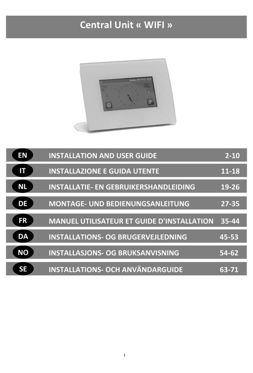
Watts Vision BT-CT02-RF User manual

Watts Vision central unit « WIFI »
&
Watts Vision central unit
2-7
EN
This manual is valid for central units with Sofware Version 2.xx

2
MAIN CHARACTERISTICS
Touch screen
Interface via internet (WIFI)
Wall mountable with power supply 85-265V (50-60)Hz
Can be placed on the table with supplied bracket and mini
USB power supply (0-5V)sold separately
Battery operation (only for settings)
RF Communication with other devices
Multiple heating/cooling devices control.
SD Card update
Intuitive menus for devices management.
Charge the central unit for at least one hour before
pairing the devices already mounted
DEVICES compatible with Watts
Vision Central unit
Hydraulic panel
heater
Electrical panel
heater
Heating
Cooling
Hydraulic floor
regulation
Electrical floor
regulation
Pilote wire
BT-FR02
RF
X
X
X
X
X
BT-WR02
RF /
BT-WR02
HC RF
X
X
X
X
X
BT-PR02
RF
X
X
BT-
M6Z02
RF
X
X
X
BT-TH02
RF
X
X
BT-A02
RF
BT-D02
RF
BT-DP02
RF
X
X
X
X
X
REPEAT
ER
50 heating master devices (thermostats) and 50 heating
slave devices (receivers).
25 ON/OFF devices with weekly program with 15 min steps.
50 lighting devices (ON/OFF).
You may have to use a Watts RF repeater if you want to
extend the RF range.
INSTALLATION
a- Wall mounting
1- Connect the power as described below :
2- Screw the power unit on the wall. Be careful ! The tab must
be on the top !
3- Put the switch on ON position
4- Mount the Central on the power unit and slide it on the
bottom to clip it. The Central is ready for operation.
b- Table installation
Connect the central unit with the cable (5V, 1A) and then mount
the leg support on it and put the switch on ON position. The
central unit is ready for operation.
NOT TO BE USED
POWER SUPPLY 85-265V - 50/60HZ
ON/OFF
ON/OFF
CABLE

3
GENERAL PICTOGRAMS
To return to the main screen.
To return to the previous screen.
The buttons with a red point need a long press (min
5s).
MAIN SCREEN
1- Date.
2- Display the hour or the ambient T° of the room or zone. Make
your choice by pressing on the central part of the screen
3- Outside sensor temperature.
4- Screen lock. A long press toggles between locking and
unlocking.
5- Error flag for the system (RF, limits, alarms, battery
anomalies…). Access to the list by pressing on this icon.
6- The device is working on battery (! only for settings and
pairing).
7- Rooms access (active even if the Central is locked to see but
not to change settings).
8- Main menu.
9- Holidays mode status.
10- Boiler status displayed if connected to the Central.
HOUR SETTING
Set the hour and the date. Then press on or
HOUSE CREATION
long press on
Create all the rooms
1. Room changing.
2. Current room name.
3. To delete a room (zone).
4. To create or add a room (zone).
5. To change current room (zone) name.
MAIN MENU
Press to go to main menu
1- Consumption statistics menu.
2- Language (the flag of the current language is
displayed).
3- General commands menu.
Use this menu to put all the same devices type in the same
operating mode.
a- To select the heating devices mode for all the installation.
b- To select the ON/OFF devices mode for all theinstallation.
c- To select the lighting devices mode for all the installation.
d- To validate the selections.
4- Heating/cooling mode management menu.
(Not available yet)
5- User settings menu.
In this menu, you can set:
- Hour, Date.
- Summer-Winter (Manual, Automatic).
- Temperature unit (°C, °F).
- Background Color.
- Buttons color
- Backlight
- Screen saver (Enabled, Disabled).
- Screen cleaner.
- Factory default user.

4
6- WIFI status.
WIFI settings reading button (refreshment).
The Internet Access password allows to link your central unit to
your Internet account (See below) for a remote control of your
system through the Internet or Smart Phone.
n.b.: At first use or software update, wait for some time until the
green State icon is active.
7- Holidays menu.
- To set the departure/return dates and hours.
- Use < or > to select year/month/day, hour & minute.
- Set and valid the operating mode of the devices in holiday
mode. (Same menu than general menu).
8- Installation menu (long press 3-4 s)
A. House creation.
B. Radio pairing.
C. Delete a device:
Select device type and then the device.
D. Delete all devices:
All devices installed in the system will be deleted (rooms
will be maintained).
E. Identify a device
To identify a device of the installation
a- To put the menu in reception mode.
b- To access to the device parameters.
Process :
-Press on ‘a’ to make the Central listening
- Press on the device receiver and wait a few seconds until
radio communication frame is transmitted.
Note: ID-number is displayed on the screen, please repeat to
be sure to have the same ID.
- Long press on to change device name, power.
F. Antifreeze setpoint:
You can set the antifreeze setpoint as reference for the whole
installation.
G. Heating settings:
You can fix setpoint limitations (min/max) per zone and the
offset assigned to devices working in floor sensor regulation.
H. WIFI settings:
To set the WIFI configurations (SSID/Protected Access Key
Type/ Password). You can do it manually or scan the active
networks.
n.b.: The connection to Internet is recommended with Certified
WiFi routers (http://www.wi-fi.org/certification).
n.b.: Automatic pairing time to WiFi router
with WEP key: 3-4 min, with WPA2 key: 1 min.
I. General factory default:
To reset the system with the factory values, but the software
version will remain the same.
J. Update Firmware:
To update the software, with the SD-card. The system is
qualified to work with SD-cards less than or equal to 16GB.
Select
to proceed.
The SW and the procedure to update the central unit is
available on: http://www.wattselectronics.com/
A
B
C
D
E
F
G
H
I
J

5
HEATING DEVICES MANAGEMENT
Press on in the main screen and after selecting the room,
on
1. Device type choice (heating, lighting, On/Off). These buttons
are only displayed if one device type is installed in the room
(colored if active).
2. Room changing.
3. Current mode, press on this icon to enter in the menu where
you can change the current operating mode.
4. Ambient temperature or setting temperature (setpoint) after one
press on 10.
5. Heating indicator (animated if heating).
6. Information about the heating devices installed in the room.
7. Set the current setpoint (deactivated if the screen is locked).
8. Current room name.
9. Quick access to the desired room.
10. To display either the ambient or setting temperature in 4.
11. Pilot wire status.
12. Floor temperature if floor regulation.
13. Only displayed if the screen is locked.
Press on « 3 » in the previous menu to access this modes
menu.
Comfort Mode : Set the room in comfort mode. If it
remains active, the comfort temperature will be followed all the
time.
Reduced Mode : Set the room in reduced mode. If it
remains active, the reduced temperature will be followed all the
time.
Timer or Boost Mode : Temporary derogation. Set the
timer duration (days, hours, minutes) by pressing on
button, then validate and set the desired temperature on main
screen.
Anti freeze Mode : Use this mode to put your room in anti-
freeze mode (the temperature is set in the Installation menu)
OFF Mode : To switch OFF the room heating. Be careful!
In this mode, your installation can freeze!
Auto Mode : In this mode, the room temperature will follow
the program you have chosen. You can choose between
existing programs or you can create a new one that you can
modify as you want.
Press on to select between :
a- Select: To select an existing program.
b- Create: To create a new program.
Select the days for which you want the same program (in the
example, Wednesday, Thursday and Friday).
Use the Comfort button to select the hourly ranges during
which the comfort temperature will be followed (brown range)
and the reduced button to select the hourly ranges during
which the reduced temperature will be followed (blue range).
Use the arrows and to put the cursor on the desired
hours.
Validate the program; the validated days are then highlighted in
green (on this example: Monday and Tuesday).
The days that are not programmed are displayed in red.
c- Edit: To view and modify an existing program
d- Information: to view the current program
P1: morning, evening & weekend.
P2: morning, midday, evening & weekend.
P3: day & weekend.
P4: evening & weekend.
P5: morning, evening (bathroom).
a
b
c
d

6
LIGHTING DEVICES MANAGEMENT
Press on in the main screen and on
1. Device type choice (heating, lighting, On/Off). These buttons
are only displayed if one device type is installed in the room
(colored if active).
2. Room changing.
3. Information about the lighting devices installed in the room.
4. Indicates both the current lighting device number / the
number of lighting devices in the room.
5. Indicates the lighting status. A press on it switches the
lighting status.
6. General management for all lighting in the room.
7. Current room.
8. Quick access to the desired room.
9. Only displayed if the number of devices is upper than 1; used
to select the devices in the room.
10. Only displayed if the screen is locked.
ON/OFF DEVICES MANAGEMENT
Press on in the main screen and on
1. Device type choice (heating, lighting, On/Off). These buttons
are only displayed if one device type is installed in the room
(colored if active).
2. Room changing.
3. Information about the device.
4. Indicates both the number of the current device / number of
devices in the room.
5. Indicates the ON/OFF status. A press on it switches the
status of the device.
6. General management for all the ON/OFF devices in the
room.
7. Current room.
8. Quick access to the desired room.
9. Only displayed if the number of devices is upper than 1; used
to select the devices in the room.
10. Long press to switch between auto mode and normal mode
(colored if active).
11. Displayed only if the device is in Auto mode, press to
access and edit the device program.
12. Only displayed if the screen is locked.
PAIRING
Create the room if it doesn’t exist
House creation
Radio pairing
- Choose the device type (heating)
- Choose the room
Note: The master must be the first paired device.
- Put the device in pairing mode (refer to device leaflet)
- Start the pairing on the Central
- Follow the instructions given by the Central (check on the
device that the pairing is successful, refer to the device
leaflet)
- n.b.: Automatic pairing time in case of RF communication
loss: 10s.
INSTALLATION TYPES (HEATING)
Type 1 :
In this configuration:
Pair first the thermostat with the Central before pairing the
other devices.
The actuators regulate on thermostat temperature.
Type 2 :
In this configuration:
Pair first the thermostat with the Central before pairing the
other devices.
The other devices regulate on thermostat temperature.
Warning! In this installation type, the BT (MASTER) must be in
regulation Air mode (not floor or Air + Floor)

7
Type 3 :
In this configuration :
The flush is inevitably in floor regulation because there is no
thermostat in the room.
Radiator receiver only paired as Heating device.
BT-WR, BT-PR, BT-FR can be configured as a plug or
lighting devices.
Type 4 :
In this configuration:
Each UFH 1 is paired with the Central and the thermostats
are paired with UFH.
During the pairing, the Central create automatically rooms
according to the number of thermostats (rooms) of UFH 1.
Default names are given to the rooms. You can modify them
in the menu “House creation” (you can identify these rooms
with different setting temperatures)
REMOTE CONTROL
You need to connect the central unit to Wifi: See Wifi setting
above.
Make sure that the central is connected to the wifi network with
an IP address (See WiFi status above) otherwise you need to
connect the central unit to WiFi.
Connect to the web pages to drive your central unit:
http://smarthome.wattselectronics.com/
Or download Watts Vision application from App store or
Google Play on your Smart Phone.
Create an account.
Validate your email.
Request a pairing code to link your central unit to your account.
The pairing code (valid 24h) is sent to in your mail box.
In the wifi status menu of the central unit, enter the pairing
code.
Your central unit should appear after a few minutes in the
application or the web page. You can then drive your central
unit from everywhere.
TECHNICAL CHARACTERISTICS
Operating temperature,
connected.
Operating temperature,
battery
Shipping and storage
temperature
-30°C to +40*C
0°C to +40°C
-30°C to +50°C
Electrical Protection
Electrical insulation
IP30
Class II
Temperature precision
0.1°C
Setting Temperature Range
- Comfort
- Reduced
- Anti-freeze
5°C to 30°C in 0.5°C steps
5°C to 30°C in 0.5°C steps
5°C to 10°C
Power Supply
85-265V 50-60 Hz
Radio Frequency
868 MHz, <10mW.
Software version
User interface: Shown on the
main menu V xxx
Wifi communication: Shown on
the wifi menu V xxx
CE Directives:
Your product has been
designed in conformity with
the European Directives.
R&TTE 1999/5/EC
LVD 2006/95/EC
EMC 2004/108/EC
RoHS 2011/65/EU
SD card
<=16GB (FAT)
WIFI
802.11b –2.4GHz
802.11g –5GHz / 2.4GHz

8
HAUPTMERKMALE
Touch-Screen
WiFi integriert
Wandmontage oder Tischaufstellung
Funk-Kommunikation mit anderen BT-xx02-RF Produkten
Funktion Heizen / Kühlen
Update Funktion via SD-Card
Tischaufstellung mit Aufsteller und Spannungsversorgung via
mini USB (5V,1A), Netzteil und Kabel nicht im Lieferumfang
Speisespannung 85-265V AC (50-60)Hz (bei Wandmontage)
Batteriebetrieb (nur zur Konfiguration)
Intuitives Menü zur Konfiguration
Laden Sie die Zentrale mindestens eine Stunde bevor
Sie mit der Konfiguration bzw. der Initialisierung der
bestehenden Funk-Komponenten beginnen
RF- EMPFÄNGER ZUR KOMBINATION
MIT ZENTRALE
Hydraulische
Flächenheizung
Elektrische
Flächenheizung
Heizung
Kühlung
Hydraulische
Bodenregulierung
Elektrische
Bodenregulierung
Pilotleiter
BT-FR02
RF
X
X
X
X
X
BT-WR02
RF /
BT-WR02
HC RF
X
X
X
X
X
BT-PR02
RF
X
X
BT-
M6Z02
RF
X
X
X
BT-TH02
RF
X
X
BT-A02
RF
BT-D02
RF
BT-DP02
RF
X
X
X
X
X
REPEAT
ER
Max. 50 Thermostate (Master) in Verbindung mit 50
Einzelempfängern (Slaves) können angesteuert werden.
Max. 25 ON/OFF Einzelempfänger mit
Wochenprogrammierung können angesteuert werden.
Max. 50 ON/OFF Licht- Empfänger können angesteuert
werden
Die Funk- Reichweite können Sie mit einem optional
erhältlichen Repaeter erhöhen.
INSTALLATION
a- Wandmontage
1- Montieren Sie die Anschlußplatte an der Wand, z.B. in UP-
Dose. ACHTUNG! Arretierung muss nach oben zeigen
2- Schalten Sie die BT-CT02-RF WiFi Zentrale EIN
3- Setzen Sie die Zentrale auf die Anschlussplatte und
schieben diese nach unten bis die Arretierung einrastet. Die
Zentrale ist nun betriebsbereit.
b- Tischaufstellung
Netzteil mit USB Kabel (5V,1A) einstecken und Tischaufsteller
an der Rückseite anbringen. Schalten Sie die Zentrale EIN. Die
Zentrale ist nun betriebsbereit.
EIN/AUS
Nicht verwenden !
SPEISESPANNUNG 85-265V - 50/60HZ
Oben !
EIN/AUS
KABEL

9
GENERELLE PIKTOGRAMME
Zurück zum Hauptbildschirm, Home-Screen
Zurück zur vorherigen Ansicht, zum letzten
Screen
Piktogramme, Buttons mit einem roten Punkt
müssen lange gedrückt werden
HAUPTBILDSCHIRM
1- Tag und Datum
2- Anzeige der Uhrzeit oder Umgebungstemperatur des Raums
bzw. der Zone. Auswahl durch drücken auf die
Bildschirmmitte.
3- Außentemperatur-Anzeige, wenn AT-Sensor verwendet wird.
4- Bildschirmsperre, durch langes drücken kann zwischen
Sperren und Entsperren gewechselt werden.
5- Warnhinweis (Funk, Alarm, Limit, Batterie leer …). Anzeige
der Details durch Drücken auf das Symbol.
6- Zentrale arbeitet im Batteriemodus (! NUR zur Konfiguration
bzw. Funkinitialisierung der Empfänger/Sender)
7- Zugriff auf Räume, Zonen (bei gesperrter Zentrale nur
Funktion Lesen, keine Möglichkeit zum verändern der
eingestellten Parameter)
8- Hauptmenü, HOME.
9- Status Betriebsart Urlaub
10- Status Kessel, wenn mit Zentrale verbinden (spezieller
Sender/Empfänger erforderlich).
EINSTELLUNG DATUM UND UHRZEIT
Datum und Uhrzeit einstellen, danach oder
drücken.
ERSTELLE HAUS
lange auf (3-4 s) drücken
Hier können alle Räume erstellt werden
1. Wechsel zwischen den einzelnen Räumen.
2. Aktuelle Raumbezeichnung, aktueller Raum.
3. Raum, Zone löschen).
4. Raum, Zone hinzufügen.
5. Änderung der aktuellen Raumbezeichnung
HAUPTMENÜ
Drücken Sie um ins Hauptmenü zu gelangen
1- Statistik Energieverbrauch.
2- Sprache (Flagge der momentan eingestellten
Sprache wird angezeigt)
3- Die gesamte Installation
Verwenden Sie dieses Menü um alle Geräte mit den gleichen
Funktionen in die gleiche Betriebsart zu versetzen.
a. Anwendung Heizen, alle Geräte werden in der
entsprechenden Betriebsart betrieben.
b. Anwendung EIN/AUS, alle Geräte werden in der
entsprechenden Betriebsart betrieben
c. Anwendung Licht, alle Geräte werden in der entsprechenden
Betriebsart betrieben
d. zur Bestätigung der Auswahl
4- Einstellungsmenü Heizen / Kühlen.
5- Benutzereinstellungen
Folgende Parameter können eingestellt werden:
- Uhrzeit, Datum
- Sommer-Winter (Manuell, Auto)
- Einheit Temperatur (°C, °F)
- Hintergrund Color
- Hintergrundbeleuchtung
- Bildschirmschoner: (Aktiv, Deaktiviert)
- Reinigung
- Werkseinstellungen Benutzereinstellungen

10
6- WiFi Einstellungen
WIFI Einstellungen Play-Taste (refresh).
Internet Kennwort lassen Sie die Zentrale und Ihre
Internetkonto zu vereinigen. (Siehe unten die Fernsteuerung
von Ihrer Internetsystem oder Smart Phone.
Anmerkung: Bei der ersten verwenung bzw. Nach einem
Software Update, warten Sie bitte einige Zeit bis das grüne Icon
Status aktiv ist.
7- Urlaub
- Eingabe Abreisedatum, Datum und Zeit der Rückkehr.
- Verwenden Sie “<” oder “>” um Jahr/Monat/Tag,
Stunde/Minute auszuwählen.
- Auswahl und bestätigen der Betriebsmodus von Geräten im
Urlaub
8- Parameter Einstellungsmenü (lange gedrückt
halten3-4 s)
a- Erstelle Hause
b- Funk-Initialisierung
c- Löschen eines Geräts
Gerätetyp auswählen und das Gerät
d- Alle Geräte löschen
Alle Geräte in dem System installiert werden gelöscht (Räume,
Zonen bleiben bestehen).
e- Identifizieren Sie ein Gerät
Zur Identifizierung eines Gerätes in der Installation
1- Zugriff auf RF Konfigurationsmodus.
2- Zugriff auf die Geräteparameter, Einstellungen
Ablauf:
- Drücken auf Taste 1 um die Zentrale anzumelden
- Drücken auf das Gerät Empfängerund warten auf einige
Sekunden bis Radio Kommunikation gesendet wurde.
Nota: ID-Nummer wird auf Bildschirmerscheint, bitte
wiederholen um sicher zu sein, die selbe ID Nummer zu haben
- Lange Drücken auf um des Namen des Geräts oder
Leistiung zu andern,r
f- Frostpunkt-Sollwert
Sie können Frostpunkt Sollwert andern, gültig für alle
Heizungskomponenten.
g- Einstellungen Heizung
Sie können Sollwertbegrenzung nach Gebiet einstellen
(min/max) und Sollwert, um Geräte, die im Bodensensor
Regelung zugeordnet sind.
h- WiFi Einstellungen
Um WIFIKonfiguration zu einstellen (SSID/Protected Access
Key Type/ Kennwort). Können Sie es manuell oder durch
Abtasten der aktiven Netzwerk.
Anmerkung: Es wird empfohlen die Internetverbindung mit
einem Zertifizierten Router durchzuführen. (http://www.wi-
fi.org/certification).
Die automatische Verbindungszeit zu eine Router mit WEP
Schlüssel beträgt ca. 4 Minuten und zu einem Router mit WPA2
Schlüssel ca. 1 Minute.
i- Allgemeine Werkseintellungen
Um das System aud die Werkeinstellungenzurücksetzen,aber
die Software-Version wird die selbe bleiben
j- Update Firmware
Um die Software mit SD Karte zu aktualisieren. Brauchen Sie
eine 16GB SD Karte maximum.
Die Software und Aktualisierungen sind auf:
http://www.wattselectronics.com/ verfügbar
a
b
c
d
e
f
g
h
i
j

11
HEIZEN
Drücken Sie auf dem Hauptbildschirm und danach auf
1. Geräteauswahl (Heizen, Licht, On/Off). Die Symbole werden
nur angezeigt wenn ein entsprechendes Gerät im Raum
installiert ist (farbig hinterlegt, wenn aktiv).
2. Wechsel zu einem anderen Raum.
3. Momentane Betriebsart des Raumes. Durch Auswahl des
Symbols gelangen Sie in das Menü um die Betriebsart zu
ändern (Details siehe unten).
4. Umgebungstemperatur im Raum, oder
Solltemperaturanzeige (Soll-Wert) nach drücken von 10.
5. Anzeige Heizbedarf (bei Heizbedarf ist das Symbol animiert).
6. Informationen über die installierten Geräte (Funktion Heizen)
im Raum.
7. Einstellung Sollwert des Raumes (deaktiviert, wenn
Bildschirm gesperrt ist).
8. Raumbezeichnung, Name des Raumes.
9. Schnellzugriff auf den gewünschten Raum.
10. Wechsel zwischen Ist- und Solltemperatur, Anzeige bei 4.
11. Status Steuerleitung
12. Fußbodentemperatur, bei Regelung via Fußbodensensor.
13. Wird nur angezeigt wenn Bildschirmsperre aktiv ist.
Drücken Sie auf « 3 » in oben beschriebenem Menü, um die
Betriebsart des Raumes festzulegen.
Betriebsart Komfort : Manuelle Betriebsart die
permanent auf die eingestellte Komforttemperatur regelt.
Betriebsart Absenkung : Manuelle Betriebsart die
permanent auf die eingestellte Absenktemperatur regelt.
Betriebsart Timer oder Boost :befristete
Ausnahmeregelung Einstellen Sie den Timer (Tage,
Stunden, Minuten) mit Taste, Dann bestätigen und
gewunschte Temperatur auf Bildschirm einstellen.
Betriebsart Frostschutz :Benützen dieses Modus um
Ihr Zimmer im Frostschutz Modus teinzustellen (Temperatur
ist im erweiterten Installationsmenü eingestellt)
Betriebsart OFF : Heizbetrieb des Raumes wird
ausgeschaltet. ACHTUNG –Gefahr des einfrieren der
Anlage!
Automatischer Betrieb : In dieser Betriebsart verfolgt
das System das ausgewähltem (Standard- oder
benutzerdefiniert) Programm entsprechend der jeweiligen
Uhrzeit und den eingestellten Sollwerten für Komfort- und
Absenktemperatur.
Programmierung, drücken Sie um zu folgender Auswahl
zu gelangen:
a- Auswahl: um ein existierendes Programm auszuwählen.
b- Erstellen: um ein neues Programm zu erstellen
Auswahl der Tage für die das gleiche Programm gelten soll (im
Beispiel Mittwoch, Donnerstag und Freitag).
Verwenden Sie das Komfort Piktogramm um die Stunden
zu definieren in welchen gemäß eingestellter Komfort
Temperatur geregelt wird (braun Balken) und das Absenkung
Pictogramm um die Stunden zu definieren in welchen
gemäß eingestellter Absenk Temperatur geregelt wird (violetter
Balken).
Mit Hilfe der Pfeile und können Sie die
entsprechenden Stunden einstellen.
Bestätigen Sie die Programmierung, programmierte und
bestätigte Tage werden grün hinterlegt (im Beispiel Montag und
Dienstag).
Tage die nicht programmiert sind werden rot hinterlegt (im
Beispiel Samstag und Sonntag).
c- Bearbeiten: zur Anzeige und Bearbeitung eines
existierenden Programms.
d- Information: Anzeige des momentanen Programms.
P1: Morgens, Abends und Wochenende
P2: Morgens, Mittags, Abends und Wochenende
P3: Wochentag und Wochenende
P4: Abends und Wochenende
P5: Morgens, Abends (Badezimmer)
a
b
c
d

12
LICHT MANAGEMENT
Drücken Sie auf dem Hauptbildschirm und danach auf
1. Geräteauswahl (Heizen, Licht, On/Off). Die Symbole werden
nur angezeigt wenn ein entsprechendes Gerät im Raum installiert
ist (farbig hinterlegt, wenn aktiv).
2. Wechsel zu einem anderen Raum
3. Informationen über die installierten Geräte (Funktion Licht) im
Raum.
4. Anzeige aktuelle Gerätenummer „Licht“ und Anzahl der Geräte
„Licht“ im Raum.
5. Zustandsanzeige, durch Drücken kann der Zustand geändert
werden.
6. Generelle ON/OFF Funktion aller installierter
„Funklichtschalter“ im Raum.
7. Raumbezeichnung, Name des Raumes.
8. Schnellzugriff auf den gewünschten Raum.
9. wird nur Angezeigt wenn mehr als ein „Funklichtschalter“ im
Raum installiert ist. Durch drücken auf die Pfeile kann zwischen
den einzelnen Schaltern hin und her gewechselt werden.
10. Wird nur angezeigt wenn Bildschirmsperre aktiv ist.
ON/OFF GERÄTE
Drücken Sie auf dem Hauptbildschirm und danach auf
1. Geräteauswahl (Heizen, Licht, On/Off). Die Symbole werden
nur angezeigt wenn ein entsprechendes Gerät im Raum installiert
ist (farbig hinterlegt, wenn aktiv).
2. Wechsel zu einem anderen Raum.
3. Informationen über die installierten Geräte (Funktion ON/OFF)
im Raum
4. Anzeige aktuelle Gerätenummer „ON/OFF“ und Anzahl der
Geräte „ON/OFF“ im Raum.
5. Zustandsanzeige, durch Drücken kann der Zustand geändert
werden.
6. Generelle ON/OFF Funktion aller installierter Geräte „ON/OFF“
im Raum.
7. Raumbezeichnung, Name des Raumes
8. Schnellzugriff auf den gewünschten Raum.
9. Wird nur Angezeigt wenn mehr als ein Gerät “ON/OFF” im
Raum installiert ist. Durch drücken auf die Pfeile kann zwischen
den einzelnen Geräten hin und her gewechselt werden.
10. Lange drücken um zwischen AUTO und Normal zu wechseln
(farbig hinterlegt, wenn aktiv)
11Angezeigt nur ob Gerät im Auto Modus ist, Drücken um Info
und Bearbeitungsfunktion zu sehen.
12. Wird nur Angezeigt wenn die Bildschirmsperre aktiv ist.
FUNK-INITIALISIERUNG
Erstellen Sie einen Raum, sollte noch keiner bestehen
Funk-Initialisierung,
- Auswahl Geräteart (Heizen)
- Auswahl Raum
ACHTUNG: Der Master muss als erstes zugewiesen werden!
- Versetzen Sie das entsprechende Gerät in den Modus
Funkinitialisierung „RF init“ (siehe hierzu die entsprechende
Bedienungsanleitung desGerätes )
- Starten Sie die Funk-Initialisierung der Zentrale
- Folgen Sie den Anweisungen auf dem Bildschirm der Zentrale
(Prüfen Sie am Empfänger ob die Initialisierung erfolgreich war,
siehe Bedienungsanleitung Empfänger)
- Anmerkung: automatisch Paarung Zeit in Falls von RF
Kommunikationausfalls: 10 Sekunden
HEIZUNGSANWENDUNGEN
Version / Typ 1:
In dieser Konfiguration:
Zuerst die Funk-Initialisierung Thermostat (Master) zu
Zentrale durchführen, danach die anderen Geräte
initialisieren.
Die HK-Ventilantriebe regeln automatisch nach der
Temperatur des Thermostats.
Version / Typ 2:
In dieser Konfiguration:
Zuerst die Funk-Initialisierung Thermostat (Master) zu
Zentrale durchführen, danach die anderen Geräte
initialisieren.
Die anderen Geräte regeln automatisch nach der Temperatur
des Thermostats.
ACHTUNG! Bei dieser Installationsart muss der BT (Master)
in der Betriebsart „Regelung Umgebungstemperatur“
betrieben werden (Boden oder Umgebung + Boden sind
NICHT möglich)

13
Version / Typ 3 :
In dieser Konfiguration:
arbeitet der UP-Empfänger mit angeschlossenem Sensor nur
in der Betriebsart Bodentemperaturregelung.
BT-TH02 RF kann nur als Heizelement initialisiert, gepaart
werden.
BT-WR, BT-PR, BT-FR können als ON/OFF oder
Beleuchtung initialisiert, gepaart werden.
Version / Typ 4 :
In dieser Konfiguration:
Die Funk-Regelverteiler UFH 1 sind mit der Touch Zentrale
verbunden und die Raumthermostate mit den Funk-
Regelverteilern. Die Raumthermostate sind dem Funk-
Regelverteiler zuerst zuzuweisen.
Während der Funk-Initialisierung der Funk-Regelverteiler
erstellt die Touch Zentrale entsprechend der Anzahl der
zugewiesenen Raumthermostate entsprechende Räume. Die
Räume werden mit Standardnamen versehen. Die
Raumbezeichnung kann angepasst werden, siehe „G.
ErstelleHaus“. Zur einfachen Identifizierung der
Räume/Thermostate stellen Sie unterschiedliche Soll-
Temperaturen an den Thermostaten ein.
Fernbbedienung
Verbinden Sie die Touch Zentrale mit ihrem WIFI Netzwerk,
Router. Siehe 8, Parameter Einstellungsmenü, Parameter h
„WiFi Einstellungen“. Nach erfolgreicher Verbindung der Touch
Zentrale mit Ihrem Router legen Sie ein Konto via Website
http://smarthome.wattselectronics.com/ an. Sie können ein
Konto auch über die Smartphone App (verfügbar für iOS und
Android) erstellen. Im App Store bzw. Play store nach „Watts
Vision“ suchen.
Nach erfolgreicher Benutzerkontoanlage beantragen Sie einen
Code/Schlüssel um eine Touch Zentrale mit Ihrem Konto zu
verbinden. In der App bzw. auf der Weboberfläche „+“
auswählen. Sie erhalten auf die zum Konto gehörige E-Mail
Adresse einen Schlüssel geschickt. Dieser Schlüssel ist 24
Stunden gültig. Tragen Sie diesen Schlüssel in denWiFi
Einstellungen unter Passwort ein. Die WiFi Einstellungen finden
Sie im Hauptmenü.
Nach einigen Minuten ist die Touch Zentrale in ihrer App bzw.
auf der Web Oberfläche sichtbar. Sie haben nun externen
Zugriff auf ihre Anlage.
TECHNICAL CHARACTERISTICS
Umgebungstemperatur, Netz-
Betrieb
Umgebungstemperatur, Akku-
Betrieb
Lagertemperatur
-30°C … +40*C
0°C … +40°C
-30°C … +50°C
Schutzart
Schutzklasse
IP30
Class II
Temperaturgenauigkeit
0,1 °C
Einstellung Temperaturen
- Komfort
- Absenkung
- Frostschutz
5°C … 30°C in 0.5°C
Schritten
5°C … 30°C in 0.5°C
Schritten
5°C … 10°C
Speisespannung
85-265V 50-60 Hz
Funkfrequenz
868 MHz, <10mW.
Software Version
Benützeroberfläche: im
hauptmenü angezeigt V xxx
Wifi Kommunikation:Im Wifi
Menü angezeigt V xxx
CE-Richtlinien
Ihr Produkt wurde in
Übereinstimmung mit den
EU-Richtlinien konzipiert.
R&TTE 1999/5/EC
LVD 2006/95/EC
EMC 2004/108/EC
RoHS 2011/65/EU
SD card
<=16GB (FAT)
WIFI
802.11b –2.4GHz
802.11g –5GHz / 2.4GHz
(Achtung ! In diesem
Fall,sollen Sie Mixed
Funktion aktivieren)

14
CARACTERISTIQUES PRINCIPALES
Ecran tactile
Interface de commande par internet (WIFI)
Fixation murale avec alimentation 85-265V (50-60)Hz
Peut être posée sur une table avec le pied fourni avec
alimentation par mini USB (0-5V) vendu séparément.
Fonctionnement sur batterie (juste pour le paramétrage)
Communication RF avec les autres appareils
Commande de plusieurs appareils chaud /froid.
Mise à jour du logiciel par carte SD
Menus intuitifs pour la gestion des appareils
Charger la centrale pendant au moins une
heure avant d’appairer les appareils déjà
montés.
APPAREILS DISPONIBLES AVEC LA
CENTRALE
Panneau chauffant
hydraulique
Panneau chauffant
électrique
Chauffage
Froid
Régulation
hydraulique de
plancher
Régulation
hydraulique de
plancher
Fil pilote
BT-FR02
RF
X
X
X
X
X
BT-WR02
RF /
BT-WR02
HC RF
X
X
X
X
X
BT-PR02
RF
X
X
BT-
M6Z02
RF
X
X
X
BT-TH02
RF
X
X
BT-A02
RF
BT-D02
RF
BT-DP02
RF
X
X
X
X
X
REPEAT
ER
50 appareils de chauffage master (thermostats) et 50
appareils de chauffage slave (récepteurs).
25 appareils ON/OFF avec programme hebdomadaire par
palier de 15 minutes.
50appareils d’éclairage (ON/OFF).
Vous devez utiliser le répéteur RF WATTS si vous voulez
étendre la bande RF.
INSTALLATION
a- Fixation murale
1- Connecter la puissance comme décrit ci-dessous
2- Visser la puissance sur le mur. Attention! L’ergot doit être en
haut!
3- Positionner le bouton sur ON
4- Monter la centrale sur la puissance et la glissant vers le bas
pour la clipser. La centrale est prête à l’emploi.
b- installation sur table
Connecter la centrale avec le câble (5V, 1A) puis clipser le
support et positionner le bouton sur ON. La centrale est prête à
l’emploi.
ON/OFF
NE PAS UTILISER
ALIMENTATION 85-265V - 50/60HZ
HAUT !
ON/OFF
CABLE

15
PICTOGRAMMES GENERAUX
Retour à l’écran principal
Retour à l’écran précédent
les boutons avec un point rouge demandent un
appui long (min 5s)
ECRAN PRINCIPAL
1- Date
2- Affichage de l’heure ou de la température ambiante d’une
pièce ou zone. Le choix se fait par appui sur le centre de
l’écran.
3- Température de la sonde extérieure.
4- Verrouillage écran. Un appui long permet de commuter
entre le verrouillage et le déverrouillage.
5- Erreur dans le système (RF, limites, alarmes, problème de
batteries …) accès à la liste par appuis sur cet icône.
6- Fonctionnement sur batterie (! Juste pour les réglages et
l’appairage)
7- Accès aux pièces (actif même si l’écran est verrouillé pour
visualiser ; les modifications ne sont pas autorisées).
8- Menu principal.
9- Mode vacances
10- Etat de la chaudière si elle est connectée à la centrale.
REGLAGE DE L’HEURE ET DE LA
DATE
Réglez l’heure et la date puis appuyez sur ou
CREATION DE LA MAISON
appui long sur
Créer toutes les pièces de la maison
1. Nom de la pièce courante
2. Pour changer le nom de la pièce courante
3. Pour ajouter une pièce
4. Pour supprimer la pièce courante
5. Pour sélectionner une autre pièce
MENU PRINCIPAL
Appuyez sur pour accéder au menu principal
1- Menu d’affichage des statistiques de
consommation
2- Langue (drapeau en fonction de la langue courante)
3- Toute l’installation
Utilisez ce menu pour mettre tous les appareils du même type
dans le même mode de fonctionnement.
a. Pour choisir le mode de fonctionnement des appareils de
chauffage de toute l’installation.
b. Pour choisir le mode de fonctionnement des appareils
ON/OFF de toute l’installation.
c. Pour choisir le mode de fonctionnement des appareils
d’éclairage de toute l’installation.
d. Pour valider les sélections
4- Menu de gestion des modes chaud / froid (non
disponible)

16
5- Menu des paramètres utilisateur
Dans ce menu, vous pouvez régler :
- Heure, date
- Eté-Hiver (manuel, automatique)
- Les unités de température (°C ou °F)
- La couleur du fond d’écran
- La couleur des boutons
- Le rétroéclairage
- Ecran de veille (activé, désactivé)
- Nettoyage écran
- Valeurs d’usine utilisateur
6- Etat du WIFI
Bouton de lecture des paramètres WIFI (rafraîchissement)
Le «Mot de passe internet » permet de lier votre unité centrale
à votre compte internet (voir ci-dessous) pour un contrôle à
distance de votre système par internet ou à l’aide de votre
smartphone.
Note : à la première utilisation ou lors d’une mise à jour du
logiciel, patientez jusqu’à ce que l’icône d’état vert soit actif
7- Menu vacances
- Permet de régler les dates et heures de départ et d’arrivée.
- Utilisez < ou > pour sélectionner année/mois/jour, heures et
minutes
Réglez et validez le mode de fonctionnement des appareils
dans le mode vacances (même menu que les commandes
générales).
8- Menu installation (Appui long 3-4s)
a- Création de la maison
b- Appairage
c- Suppression d’un appareil
Sélectionner le type d’appareil puis l’appareil
d- Suppression de tous les appareils
Tous les appareils installés dans le système seront supprimés
(les pièces seront maintenues)
e- Identifier un appareil
Pour identifier un appareil de l’installation
1- Pour mettre le menu en mode de réception.
2- Pour accéder aux paramètres de l’appareil.
Procédure:
-Appuyez sur ‘1’ pour mettre la centrale en écoute
- Appuyez sur l’appareil à identifier et attendez quelques
secondes jusqu’à ce que la fenêtre de communication radio
radio soit transmise.
Note : le numéro ID est affiché sur l’écran. Répétez l’opération
pour être sûre d’avoir le même numéro ID.
- Faire un appui long sur pour changer le nom de
l’appareil, la puissance, …
f- Min/Max/Hors gel
Pour régler la consigne de hors gel référente à toute
l’installation
g- Chauffage et rafraîchissement
Pour fixer la limitation de consigne (min/max) par zone et le
décalage attribué aux appareils fonctionnant en régulation par
le sol
h- Paramètres WIFI
Pour régler les configurations WIFI (SSID / type de clé d'accès
protégé / mot de passe). Vous pouvez le faire manuellement ou
scanner les réseaux actifs.
Note : la connexion à internet est recommandée avec les
routeurs Wifi certifiés ( http://www.wi-fi.org/certification ).
Note : temps d’appairage à un router Wifi avec la clé WEP : 3-4
minutes, et avec la clé WPA2 : 1 minute
i- Valeurs d’usine générales
Pour réinitialiser le système avec les valeurs usine, la versiono
du logiciel reste la même.
j- Mise à jour logiciel
Pour mettre à jour la version du logiciel avec la carte SD.
Le système est conçu pour fonctionner avec des cartes SD
inférieures ou égales à 16GB.
Sélectionnez
pour lancer la procédure.
Le logiciel et la procédure de mise à jour de l’unité centrale est
disponible à l’adresse suivante :
http://www.wattselectronics.com/
a
b
c
d
e
f
g
h
i
j

17
GESTION DES APPAREILS DE
CHAUFFAGE
Appuyez sur sur l’écran principal puis après avoir
sélectionner la pièce sur
1- Choix du type d’appareil (chauffage, éclairage, On/Off). Ces
boutons sont seulement affichés si un appareil de ce type est
installé dans la pièce (logo en couleur si présent dans la pièce)
2. Pour changer de pièce
3. Mode courant, 1 appui permet d’entrer dans le menu pour
changer le mode de fonctionnement,
4. Température ambiante ou température de consigne après un
appui sur 10.
5. Indicateur de chauffe (animation si chauffe)
6. Permet d’accéder aux informations des appareils de chauffage
installés dans la zone
7. Réglage de la consigne courante (bloqué si le verrouillage
écran est valide)
8. Nom de la zone courante
9. Accès rapide à la zone souhaitée
10. Permet de switcher 4 entre ambiant et consigne
11. Etat du fil pilote
12. Température sol, si régulation sol
13. N’apparait que si l’écran est verrouillé
Appuyez sur « 3 » dans le menu précédent pour avoir accès à
ce menu de modes.
Mode Confort : La pièce suit le mode confort. S’il reste
actif, la température de confort sera constamment suivie.
Mode Economique : La pièce suit le mode économique.
S’il reste actif, la température réduite sera constamment suivie.
Mode Timer ou Boost : Dérogation temporaire. Réglez la
durée (jours, heures, minutes) en appuyant sur , puis
validez et réglez la température désirée.
Mode Hors-gel : Utilisez ce mode pour mettre votre pièce
en mode hors gel (la température est réglée dans le menu
Installation)
Mode OFF : Pour éteindre le chauffage de la pièce.
Attention ! dans ce mode, l’installation peut geler !
Mode Auto : Dans ce mode, la température de la pièce
suivra le programme choisi. Vous pouvez choisir entre des
programmes usine et des programmes que vous créez et que
vous pouvez modifier comme vous le souhaitez.
Appuyez sur pour choisir entre :
a- Sélectionner: pour sélectionner un programme existant.
b- Créer: pour créer un nouveau programme
Sélectionner les jours pour lesquels vous souhaitez le même
programme (sur cet exemple : mercredi, jeudi et vendredi)
Utiliser le bouton Confort pour déterminer les plages
horaires pendant lesquelles la température de confort sera
suivie (plages oranges) et le bouton Eco pour les plages
horaires pendant lesquelles la température éco sera suivie
(plages bleues)
Utiliser les flèches et pour déplacer le curseur vert
sur les heures souhaitées.
Valider la programmation, les jours ainsi validés sont alors
surlignés en vert (sur cet exemple : lundi et mardi)
Les jours non programmés apparaissent en rouge.
c- Modifier: Pour visualiser et modifier un
programme existant
d- Information: Pour visualiser le programme suivi
P1 : Matin, soir et weekend
P2 : Matin, journée, soir et weekend
P3 : journée et weekend
P4 : soir et weekend
P5 : matin, soir (salle de bain)
a
b
c
d

18
GESTION DE L’ECLAIRAGE
Appuyez sur sur l’écran principal puis sur
1- Choix du type d’appareil (Chauffage, éclairage, On/Off)
ces boutons apparaissent que si un de ces types
d’appareil est installé dans la pièce. (couleur si actif…)
2- Permet de changer de zone
3- Informations de l’appareil
4- Indique le numéro de l’appareil d’éclairage courant / le
nombre de lampe dans la pièce
5- Indicateur d’état de l’éclairage, un appui permet de
commuter l’état de l’éclairage
6- Commande générale de tout l’éclairage de la pièce
7- Zone courante
8- Accès rapide à la zone souhaitée
9- N’apparait que si le nombre d’appareil est supérieur à 1 et
permet de naviguer dans les appareils de la pièce
10- N’apparait que si l’écran est verrouillé
GESTION DES APPAREILS ON/OFF
Appuyez sur sur l’écran principal puis sur
1- Choix du type d’appareil (Chauffage, éclairage, On/Off)
ces boutons apparaissent que si un de ces types
d’appareil est installé dans la pièce. (NB, couleur si
sélectionné…)
2- Permet de changer de zone
3- Informations de l’appareil
4- Indique le numéro de l’éclairage courant / le nombre de
lampe dans la pièce
5- Indicateur d’état de l’état On/Off, un appui permet de
commuter l’état de l’éclairage
6- Commande générale de tout l’éclairage de la zone
7- Zone courante
8- Accès rapide à la zone souhaitée
9- N’apparait que si le nombre d’appareil est supérieur à 1 et
permet de naviguer dans les appareils de la pièce
10- Permet de commuter par appui long entre le mode auto et
le mode normal (image couleur si mode auto actif)
11- N’apparait que si l’appareil est en mode auto, appuyez
pour accéder et éditer le programme de l’appareil.
12- N’apparait que si l’écran est verrouillé
APPAIRAGE
O
Créer la pièce si elle n’existe
Appairage
- Choisissez le type d’appareil (chauffage)
- Choisissez la pièce
Note: Le master doit être le premier appareil appairé!
- Mettre l’appareil à appairer en mode appairage (se référer à
la notice de l’appareil)
- Démarrer l’appairage sur la centrale
- Suivre les instructions sur la centrale (s’assurer sur l’appareil
à appairer que l’appairage a bien réussi – voir la notice de
l’appareil)
- Note : Le temps d’appairage automatique en cas de perte de
communication radio : 10 secondes.
FF
TYPES D’INSTALLATION
(CHAUFFAGE)
Type 1 :
Dans cette configuration
Appairez d’abord le thermostat avec la centrale avant
d’appairer les autres appareils
Les vannes régulent suivant la température du thermostat.
Type 2 :
Dans cette configuration
Appairez d’abord le thermostat avec la centrale avant
d’appairer les autres appareils
Les autres appareils régulent suivant la température du
thermostat
Attention ! Dans ce type d’installation, le master doit être en
mode régulation Air (en aucun cas plancher ou Air + plancher)

19
Type 3 :
Dans cette configuration :
Le flush est obligatoirement en régulation sonde sol, car il n’y
a aucun thermostat dans la pièce.
Le récepteur radiateur doit être uniquement appairé en tant
qu’appareil de chauffe.
les BT-WR, BT-PR et BT-FR peuvent être configurés en tant
que prise ou appareil d’éclairage.
Type 4 :
Dans cette configuration :
Chaque UFH 1 est lié à la centrale et les thermostats sont
liés aux UFH
À l’appairage, La centrale crée automatiquement le nombre
de pièces gérées par l’UFH en leur donnant des noms par
défaut que vous pouvez modifier dans le menu de création
des pièces (vous pouvez identifier ces pièces en mettant des
consignes différentes)
CONTROLE A DISTANCE
Vous devez connecter votre unité centrale au Wifi : se reporter
au chapitre « Paramètres Wifi » plus haut.
Assurez-vous que l’unité centrale est connectée au réseau Wifi
avec une adresse IP (voir plus haut) sinon vous devez
connecter l’unité centrale au Wifi.
Connecter à la page web suivante pour piloter votre unité
centrale :
http://smarthome.wattselectronics.com/
Ou téléchargez l’application WATTS VISION depuis App store
ou Google play sur votre smartphone.
Créez un compte.
Validez votre adresse email.
Demandez un code d’appairage pour lier votre unité centrale à
votre compte.
Le code d’appairage (valide pendant 24heures) est envoyé sur
votre boîte mail.
Dans le menu « Paramètres Wifi » de l’unité centrale, entrez le
code d’appairage.
Votre unité centrale doit apparaître après quelques minutes sur
votre application ou sur la page web. Vous pouvez alors piloter
votre unité centrale de partout.
CARACTERISTIQUES TECHNIQUES
Température de
fonctionnement
(secteur)
Température de
fonctionnement
(batterie)
Température de
transport et
stockage
-30°C to +40*C
0°C to +40°C
-30°C to +50°C
Protection électrique
Catégorie
IP30
Class II
Précision de la
température
0.1°C
Plage de réglage de
la température
- Confort
- Economique
- Hors gel
5°C à 30°C par pas de 0.5°C
5°C à 30°C par pas de 0.5°C
5°C à 10°C
Alimentation
85-265 50-60 Hz
Fréquence radio
868 MHz, <10mW.
Version du logiciel
Interface utilisateur : affiché
dans le menu principal Vxxx
Communication Wifi : affiché
dans le menu Wifi Vxxx
Directives CE
Votre produit a été
conçu en conformité
avec les directives
européennes :
R&TTE 1999/5/EC
Basse Tension 2006/95/EC
CEM 2004/108/EC
RoHS 2011/65/EU
Carte SD
<= 16GB (FAT)
WIFI
802.11b –2.4GHz
802.11g –5GHz / 2.4GHz
(Note: in this case it is necessary
to activate a function "Mixed")

20
CARATTERISTICHE PRINCIPALI
Schermo Touch-Screen a colori 4.3”.
Interfaccia via internet (Wi-Fi).
Montaggio a muro con alimentazione 85-265V (50-60)Hz.
Fornito di supporto da tavolo, con cavetto di alimentazione
(0-5V) venduto separatamente.
Operatività con batterie (solo per la fase settaggi).
Comunicazione RF con gli altri dispositivi.
Controllo di molteplici dispositivi di Riscaldamento/
(Raffrescamento), Illuminazione, prese On/Off.
Aggiornamento tramite carta micro SD.
Menu intuitivi per la gestione dei dispositivi.
Caricare l’unità centrale per almeno 1 ora prima di
abbinare i dispositivi già montati.
DISPOSITIVI compatibili con la
Centrale Watts®Vision
Pannello Radiante
Radiatore
Idraulico
Termoconvettore,
Radiatore Elettrico
Riscaldamento
Raffrescamento
Regolazione per
pavimento
radiante idraulico
Regolazione per
pavimento
radiante elettrico
Filo pilota
BT-FR02
RF
X
X
X
X
X
BT-WR02
RF /
BT-WR02
HC RF
X
X
X
X
X
BT-PR02
RF
X
X
BT-M6Z02
RF
X
X
X
BT-TH02
RF
X
X
BT-A02 RF
BT-D02 RF
BT-DP02 RF
X
X
X
X
X
Ripetitore
(*)
50 dispositivi di riscaldamento Master (termostati) e 50
dispositivi di riscaldamento Slave (ricevitori).
25 dispositivi ON/OFF con programma settimanale con
scalini di 15 min.
50 dispositivi d’Illuminazione (tramite ON/OFF).
N.B. Potreste avere la necessità di usare un ripetitore (*)
RF Watts per estendere la portata del segnale RF.
INSTALLAZIONE
a- Montaggio a muro:
5- Collegare l’alimentazione elettrica come descritto sotto:
6- Avvitare l’unità di alimentazione sul muro. Attenzione ! La
linguetta deve essere orientato verso l’alto !
7- Posizionare l’interruttore su ON.
8- Montare la Centrale sull’ unità di alimentazione e farla
scivolare verso il basso per agganciarla. La Centrale è
pronta per l’ uso.
a- Installazione da tavolo:
Collegare l’unità Centrale con il cavetto (5V, 1A), inserirvi il
supporto posteriore e quindi posizionare l’interruttore su ON.
L’unità Centrale è pronta per l’ uso.
NON USARE
ALIMENTAZIONE ELETTRICA 85-265V - 50/60HZ
ON/OFF
ON/OFF
CAVETTO
Table of contents
Languages:
Other Watts Control Panel manuals
Popular Control Panel manuals by other brands
olympia electronics
olympia electronics BS-1632 manual
Honeywell
Honeywell Symphony Frequently asked questions

American Standard
American Standard NEXIA ACONT624AS42DA user guide
Lumel
Lumel MT series Service manual
Biamp
Biamp Apprimo Touch 8i Installation and operation guide
SANJIANG
SANJIANG SEC1000 Installation & commissioning manual
Sensitron
Sensitron PL4+ Quick installation guide

BFT
BFT VEGA-VEGA ULTRA installation manual
Interlogix
Interlogix Alliance AL-4017 installation manual

Menvier Security
Menvier Security TS400 Installation & programming instructions
Autronica
Autronica BS-100 DYFI Operator's handbook
Kentec Electronics
Kentec Electronics Sigma ZXT Operation manual
