manuals.online logo
Brands
  1. Home
  2. •
  3. Brands
  4. •
  5. Siemens
  6. •
  7. Control Panel
  8. •
  9. Siemens SXL-EX Instruction Manual

Siemens SXL-EX Instruction Manual

P/N 315-095997-6
Siemens Building Technologies, Inc.
8 ernwood Road
lorham Park, New Jersey 07932
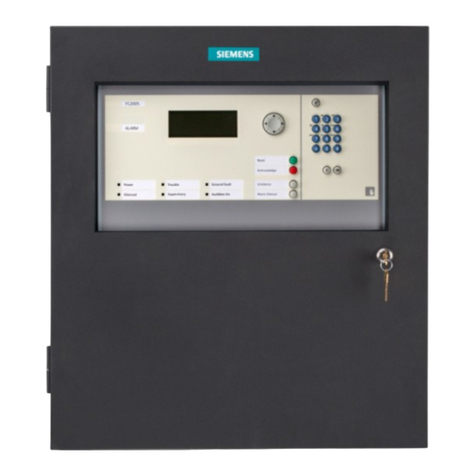
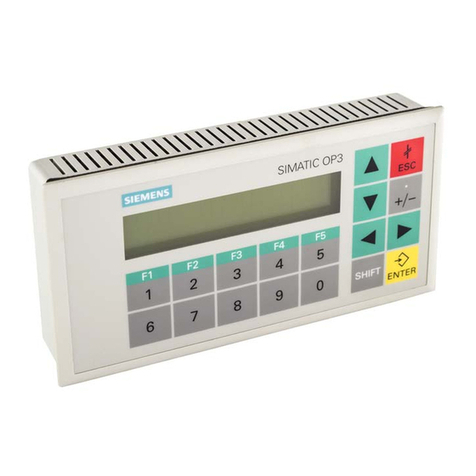
SXL-EX CONTROL PANEL
(For SXL-EX Firmware Revision 2.0 and higher)
Operation, Installation, and Maintenance Manual
Siemens Building Technologies, Ltd.
2 Kenview Boulevard
Brampton, Ontario L6T 5E4 CN
Fire Safety
Technical Manuals Online! - http://www.tech-man.com
firealarmresources.com
i
Table of Contents
1 INTRODUCTION .....................................................................................................................1
Firmware Revisions ............................................................................................................1
Standard Components .......................................................................................................2
MAIN BOARD ................................................................................................................................2
DISPLAY ........................................................................................................................................ 2
FRONT PANEL FUNCTIONS .......................................................................................................... 3
2 INSTALLATION.........................................................................................................................5
Unpackin the Equipment ..................................................................................................5
Installin the Control Panel ................................................................................................ 6
3 OPERATING MODES ...............................................................................................................9
Alarm .................................................................................................................................... 9
Supervisory.......................................................................................................................... 9
Zone Trouble ........................................................................................................................ 9
SYSTEM TROUBLE (FAULT) CODES .......................................................................................... 9
Normal .................................................................................................................................. 9
Pro ram/Test ....................................................................................................................... 9
Respondin to a Fire Alarm ...............................................................................................9
HOW THE SYSTEM ANNUNCIATES FIRE ALARMS ................................................................... 9
TO ACKNOWLEDGE ALARMS ................................................................................................... 10
TO SILENCE THE NOTIFICATION APPLIANCE CIRCUITS ....................................................... 10
TO RESET .................................................................................................................................. 10
Respondin to a Supervisory Condition ........................................................................ 10
HOW THE SYSTEM ANNUNCIATES SUPERVISORIES ............................................................ 10
TO ACKNOWLEDGE SUPERVISORIES .................................................................................... 10
TO RESET .................................................................................................................................. 10
Respondin to a Trouble Condition ................................................................................10
HOW THE SYSTEM ANNUNCIATES TROUBLES ...................................................................... 10
TO ACKNOWLEDGE TROUBLES .............................................................................................. 11
TO RESET .................................................................................................................................. 11
System Features ............................................................................................................... 11
INITIATING DEVICE CIRCUIT (ZONE) TYPES .......................................................................... 11
ALARM VERIFICATION ..............................................................................................................11
GENERIC ZONE ......................................................................................................................... 12
NOTIFICATION APPLIANCE CIRCUIT (NAC OR BELL CIRCUIT TYPE) ................................... 12
Simple Zone Code ................................................................................................................... 12
SET OUTPUT CONTROL MATRIX ............................................................................................. 13
BYPASS ZONES AND OUTPUTS ............................................................................................... 13
SET SYSTEM TIMING ................................................................................................................ 13
ALARM VERIFICATION RETARD/RESET TIMER SELECTION ................................................. 13
SET SYSTEM PASSWORD ........................................................................................................ 14
SET AC FAIL SIGNAL DELAY ..................................................................................................... 14
ENABLE SYSTEM OPTION CARDS ........................................................................................... 14
ONE PERSON SYSTEM TEST ................................................................................................... 14
LAST EVENT RECORD .............................................................................................................. 15
Pro ram Mode ................................................................................................................... 15
PROGRAM LEVEL DESCRIPTIONS ............................................................................................ 15
Section Page
Technical Manuals Online! - http://www.tech-man.com
firealarmresources.com
ii
List of Illustrations
1. SXL-EX Control Panel ............................................................................................................ 1
2. SXL-EX Front Panel ............................................................................................................... 2
3. SXL-EX Enclosure.................................................................................................................. 5
4. Transformer ounting ............................................................................................................ 6
5. ounting the Standoffs and Spacers ...................................................................................... 6
6. ounting the SXL-X ain Board ........................................................................................... 7
7. Line Graph of Alarm Verification .......................................................................................... 12
8. SXL-EX Connection Diagram ..............................................................................................31
9. SXL-EX-INT Connection Diagram ....................................................................................... 32
Page
Figure
1. Program ode Levels ..........................................................................................................23
2. Test ode Levels ................................................................................................................. 24
3. System Fault Troubleshooting .............................................................................................. 25
4. Electrical Requirements for Battery Calculations and Power anagement .......................... 26
5. Field Wiring Checkout Procedure......................................................................................... 27
6. Default Configurations ......................................................................................................... 28
7. Programming Sheet ............................................................................................................. 29
List of Tables
ENABLING THE PROGRAM MODE ..............................................................................................16
Enter Password ......................................................................................................................... 16
Reading the SXL-EX Display .....................................................................................................16
To Select Program Mode ..........................................................................................................16
To E it Program Mode .............................................................................................................. 16
Test Mode .......................................................................................................................... 20
Reading the SXL-EX Display .................................................................................................... 20
TEST LEVEL DESCRIPTIONS ..................................................................................................... 20
ENABLING THE TEST MODE ...................................................................................................... 20
Enter Password ........................................................................................................................ 20
To Select Test Mode ................................................................................................................ 20
To E it Test Mode .................................................................................................................... 20
4 CHECKOUT PROCEDURE ....................................................................................................25
Maintenance ...................................................................................................................... 25
PERIODIC INSPECTION AND TESTING .................................................................................... 25
SERVICING ................................................................................................................................. 25
FIELD WIRING CHECKOUT PROCEDURE ............................................................................... 27
SXL-EX CONNECTION DIAGRAM ............................................................................................31
SXL-EX-INT CONNECTION DIAGRAM .....................................................................................32
Table of Contents (Cont.)
Section Page
Technical Manuals Online! - http://www.tech-man.com
firealarmresources.com
1
SXL-EX Operation, Installation, and Maintenance Manual
INTRODUCTION
The SIEMENS SXL-EX is a microprocessor
based fire and life safety system with four
conventional initiating device circuits (up to 8
with the addition of the optional SZE- X or
SZE-8AX zone expander). All basic alarm and
trouble functions are annunciated and con-
trolled from the SXL-EX front panel (See
Figure 1) which consists of:
 Seven segment numeric display
 Four user-control switches
 Red and yellow LEDs for each of the
eight zones
 Six system status LEDs
Key features of the SXL-EX are:
 2 Class B (Style Y) +2 VDC notification
appliance circuits (NACs) rated at 1.5
amps each.
 Silenceable/Non-Silenceable notification
appliance circuits (NACs).
 Fully supervised initiating and notification
circuits.
 Initiating and notification circuits power
limited.
 Class B (Style B) 2 wire initiating
device circuits that are expandable to 8
circuits.
 Supports up to 30 non-shorting devices
per initiating device circuit.
 Selectable alarm verification option for
each initiating device circuit.
 One person system test with or without
audible confirmation.
 User-alterable factory installed configura-
tion.
 One Form C system Alarm relay.
 One Form C system Trouble relay.
 Seven segment numeric status display.
 Six LED status indicators.
 Easy-to-use front panel function keys.
1
 Standard 120 VAC operation with the
SXL-EX or 220/2 0 VAC operation with
the SXL-EX-INT.
 Alarm Coding (March Time, Temporal, or
Simplified Zone Code) and Non-
Silenceable output option.
 Easy-to-use built-in diagnostics.
 2 hour re-sound for Alarm and Trouble
conditions that are not restored to normal
after being acknowledged.
 Optional SZE-8AX module converts the
system to four Class A (Style D) Initiating
Device Circuits and two Class A (Style Z)
Notification Appliance Circuits and also
provides four additional Class A (Style D)
Initiating Device Circuits.
 Optional SRC-8 module provides eight
programmable Form C relays.
 Optional LED-3/ module provides
remote annunciation for eight zones with
16 LEDs. Up to two may be used.
 Optional SLT-1 module provides Leased
Line/Municipal Tie connection.
FIRMWARE REVISIONS
This manual references SXL-EX firmware 2.0.
Figure 1
SXL-EX Control Panel
SXL-EX
SIEMENS
Technical Manuals Online! - http://www.tech-man.com
firealarmresources.com
2
SXL-EX Operation, Installation, and Maintenance Manual
Standard Components
A standard four zone SXL-EX has one
modulethe main board. An expander board
is added to provide four additional zones,
when needed.
MAIN BOARD
The Main board of the SXL-EX or SXL-EX-INT
contains the intelligence for the system and
performs all of the input/output processing as
listed below:
Two supervised Notification Appliance
Circuits provide 2 VDC at 1.5 amps.
Each circuit operates Class B (Style Y)
and can be independently programmed
to operate a number of different ways
(Non-Coded, March Time, Temporal, or
Simple Zone Code).
Two Form C relays rated at 30 VDC at 1
amp resistive, 30 VAC at 500mA resis-
tive. These relays are for Alarm and
Trouble operation.
 A dual mode battery charger that
provides float and constant current
Figure 2
SXL-EX Front Panel
modes of charging sealed lead acid
batteries (15 Amp-Hour maximum).
Nonvolatile storage of system con-
figuration so that configuration remains
intact during loss of system power.
Four supervised power limiting
Initiating Device Circuits Each circuit
operates Class B (Style B) and can be
independently programmed to operate as
an Automatic Alarm input, a Verified
Alarm input, a Supervisory input, or a
Generic input. Each initiating device
circuit can use an unlimited number of
manual shorting-type devices.
CPU Fail LED
DISPLAY
The SXL-EX display, shown in Figure 2,
provides the user with the necessary inter-
face to operate the fire detection system in
Normal, Test, and Program modes.
Technical Manuals Online! - http://www.tech-man.com
firealarmresources.com
3
SXL-EX Operation, Installation, and Maintenance Manual
CODE DESCRIPTION
1 AC power fail
2 NAC 1 trouble
3 NAC 2 trouble
4 Ground fault
5 Municipal tie fault
6 Battery fault
7 System Configuration fault
8 Auxiliary port fault
9 Outputs bypassed
0 Hardware failure
E Enter password
A Password accepted
F Password fail
P Program mode
tTest mode
L Leave Program/Test mode
The Function Keys
The ACK key is used to acknowledge alarms,
troubles, and supervisory conditions. In general
the LEDs change rom pulsing to steady to
indicate that the condition was acknowledged.
The SILENCE key silences the noti ication
appliance circuits that are con igured as
silenceable. Pressing the SILENCE key a
second time causes the NACs to re-sound.
The RESET key resets the SXL and all o the
smoke detectors.
The DRILL key activates all o the noti ication
appliance circuits.
The yellow zone status LEDs indicate
a trouble or supervisory condition existing on a
particular input. Pulsing indicates the condition
was not acknowledged; on steady indicates it
was acknowledged.
The red zone status LEDs provide an
indication o the status o a particular zone.
Pulsing indicates an alarm condition in that
zone. When the alarm is acknowledged, the LED
remains on steady until the panel is reset.
FRONT PANEL FUNCTIONS
The front panel of the SXL-EX is comprised of
a seven segment display, function keys, and
LEDs. Their functions are described below
(Refer to Figure 2):
The LEDs
The green Power LED remains on steady when
AC power is connected and pulses when the unit
is operating rom batteries.
The red Alar LED pulses when an alarm is
detected until it is acknowledged. Then it remains
on steady until the alarm condition is reset.
The yellow Supervisory LED pulses when a
supervisory condition is detected until it is ac-
knowledged. Then it remains on steady until the
supervisory condition is reset. Note that the
pulsing rates o the trouble and supervisory
conditions are di erent.
The yellow Trouble LED pulses when a trouble
condition is detected until it is acknowledged.
Then it remains on steady until the trouble condi-
tion is reset. Note that the pulsing rates o the
trouble and supervisory conditions are di erent.
The yellow Bypass/Alar Silence LED is on
steady when a zone in the system is bypassed
and it pulses when a noti ication circuit is silenced.
When an initiating device zone is bypassed, the
appropriate yellow zone trouble LED is on.
The Test/Progra LED is on steady when the
Test mode is selected and it pulses when the
Program mode is selected.
The Sounder
CONDITION RATE OF PULSATION
SYSTEM ALARM Sounds steady
TROUBLE Pulses at 50% duty cycle
SUPERVISORY Pulses at 25% duty cycle
CPU FAILURE Pulses once every 2 seconds
The seven seg ent display indicates
the various system troubles and the programming
and test modes. The numbers and symbols that
appear on this display are described in the
ollowing chart.
Technical Manuals Online! - http://www.tech-man.com
firealarmresources.com
4
SXL-EX Operation, Installation, and Maintenance Manual
Technical Manuals Online! - http://www.tech-man.com
firealarmresources.com
5
SXL-EX Operation, Installation, and Maintenance Manual
INSTALLATION
Unpacking the Eq ipment
The SXL-EX is shipped in two cartons;
one of the cartons contains the SXL-EX
enclosure The other carton contains the
SXL-EX electronics, the transformer, and
the mounting hardware Follow the proce-
dure below to unpack the SXL-EX equipment.
1. Locate and open the shipping carton
containing the EN-SX enclosure. Remove
the packing material and inspect the
enclosure for damage.
Note: If the enclosure is damaged,
contact the shipping carrier
immediately to report the damage.
2. Locate and open the shipping carton
containing the SXL-EX electronics.
2
Figure 3
SXL-EX Enclosure
Remove the packing material, and inspect
the electronics for damage.
Note: If the PC board is damaged,
contact the shipping carrier
immediately to report the damage.
3. Check that the following items are inside
the carton:
 Mounting hardware for the SXL-X Main
Board and transformer
 Main board
 Power transformer
Note: If any of the above items are
missing, contact the distributor
from whom you ordered the unit.
SXL-EX
SIEMENS
Technical Manuals Online! - http://www.tech-man.com
firealarmresources.com
6
SXL-EX Operation, Installation, and Maintenance Manual
Installing the Control Panel
Remove all system power before
installation, first battery and then AC
(To power up, connect the
AC first, then the battery.)
All wiring must comply with
national and local codes.
Install the SXL-EX control panel by following
the steps listed below.
1 Install the enclosure Fasten the
enclosure securely to a clean, dry, shock
and vibration free surface. Consider the
following placement factors when
mounting the enclosure: height as it
relates to the front panel, weight and size
of the enclosure, and local mounting
codes. Refer to the EN-SX Installation
and Power Limited Wiring Instructions,
P/N 315-09599 , for further information.
Figure
Transformer Mounting
2 Fasten the power transformer to the
inside of the enclosure Mount the
transformer on the four studs in the upper
left-hand corner of the EN-SX enclosure,
as shown in Figure , using the hardware
provided.
3 Pull all field wiring into the enclosure
Dress the wiring to the approximate
location to which it will go on the SXL-X
Main board.
4 Install the PC Board mounting metal
hex standoffs and plastic spacers
Mount the six PC Board metal hex stand-
offs and two plastic round spacers, as
shown in Figure 5.
5 Install the Main board Mount the Main
board to the standoffs in the center of the
enclosure (Refer to Figure 6).
a. Fasten two of the six screws provided
in the PC board mounting hardware in
the two bottom metal hex standoffs
Figure 5
Mounting the Standoffs and Spacers
Technical Manuals Online! - http://www.tech-man.com
firealarmresources.com
7
SXL-EX Operation, Installation, and Maintenance Manual
labeled A in Figure 6, leaving a 1/4 inch
gap between the standoff and the
head of the screw.
b. Place the slots on the bottom of the
SXL-X Main board on the two screws.
c. Secure the board in place by fasten-
ing the remaining four screws labeled
B to the metal hex standoffs.
d. Tighten the bottom two screws.
6 Optional modules Refer to the specific
optional module Installation Instruction
sheet for the appropriate installation.
7 Before connecting any wire to its
screw terminal, refer to the Checkout
Procedure (page 27) and the SXL-EX
Connection Diagram (Figure 8, page 31)
or the SXL-EX-INT Connection
Diagram (Figure 9, page 32), as
applicable. Prior to connecting wiring to
the Main board, ensure compliance to
maximum resistance in accordance with
the Field Wiring Checkout procedure,
page 27. Make sure that all power is off
before connecting leads.
8 Install power wiring to the SXL-EX The
SXL-EX is designed to operate from a
120 VAC, 60 Hz power source.
Use a dedicated circuitbreaker. Wire in
accordance with local codes and/or
Article 760 of the National Electrical
Code, NFPA 72, latest edition.
a. Run Earth Ground from a suitable
source to the Earth Ground stud on
the chassis (See Figure 6 for the
location of the stud). Secure in place
using the two #8 nuts provided. Check
local requirements. Conduit is not an
acceptable ground
b. Connect the 120 VAC source and the
BLACK transformer wire leads
to TB1.
Figure 6
Mounting the SXL-X Main Board
c. Connect the BROWN transformer
wire leads to TB6.
9. Install power wiring to the SXL-EX-INT
The SXL-EX-INT is designed to operate
from a 220/2 0 VAC, 50/60 Hz power
source. See the SXL-EX 220/2 0 VAC
Transformer Wiring Installation
Instructions, P/N 315-0962 6 and the
SXL-EX-INT Connection Diagram (Figure
9, page 32).
Technical Manuals Online! - http://www.tech-man.com
firealarmresources.com
8
SXL-EX Operation, Installation, and Maintenance Manual
Technical Manuals Online! - http://www.tech-man.com
firealarmresources.com
9
SXL-EX Operation, Installation, and Maintenance Manual
OPERATING MODES
The SXL-EX annunciates the following
modes of operation:
 Alarm
 Supervisory
 Trouble
 Normal
 Program/Test
Alarm
The SXL-EX Display board lights the
appropriate red alarm LED and the general
ALARM LED to indicate to the user that an
Alarm condition exists on an initiating device
circuit (IDC).
S pervisory
A Supervisory alarm condition is indicated on
the SXL-EX by the SUPERVISORY LED
flashing along with the appropriate yellow
zone LED.
Zone Tro ble
A Trouble condition is displayed by a
flashing TROUBLE LED along with the
appropriate yellow zone LEDs.
System Trouble (Fault) Codes
A number is displayed in the seven segment
display to indicate System Trouble (Fault)
Codes. They are:
Code 1: AC Power Fail/Brownout
Code 2: Notification Appliance Circuit 1
Code 3: Notification Appliance Circuit 2
Code 4: Ground Fault
Code 5: Municipal Tie Fault
Code 6: Battery Fault
Code 7: System Configuration Fault
Code 8: Auxiliary Port Fault
Code 9: Output Bypassed
Code 0: Hardware Failure
3
For a further description of the system fault
codes, see System Fault Troubleshooting
(Table 3, page 25).
Normal
The Normal Mode is the absence of any
alarm, supervisory, or trouble condition. The
POWER LED is lit in Normal mode when the
system has AC power. The Alarm, Trouble,
Supervisory, Bypass, and Zone status
LEDs are off, and the internal sounder is off.
Program/Test
The Program/Test Mode is used for system
configuration, test, and maintenance func-
tions. When the SXL-EX is in Program
Mode, it does not indi ate alarm or super-
visory onditions.
The System resets to normal mode after 2
minutes of front panel inactivity. When the
SXL-EX is in the One Person System Test
Mode, it automatically returns to normal
mode after 20 minutes of inactivity.
Responding to a Fire Alarm
How the System Annun iates Fire Alarms
When a fire is detected on one of the initiat-
ing device circuits (IDCs), the SXL-EX
causes the System ALARM LED and the
appropriate Zone ALARM LED on the front
panel to flash and the systems internal
audible to sound.
NOTE: Follow the response plan approved
by the local authority having
jurisdiction.
Technical Manuals Online! - http://www.tech-man.com
firealarmresources.com
10
SXL-EX Operation, Installation, and Maintenance Manual
To A knowledge Alarms
1. Unlock and open the door.
2. Press ACK to acknowledge (Block
Acknowledge) all alarms and other
conditions. The system ALARM and the
Zone ALARM LEDs on the front panel
stop flashing and remain on. The
systems internal audible silences.
To Silen e The Notifi ation Applian e
Cir uits
Press SILENCE after all alarms are acknowl-
edged. The BYPASS LED on the front panel
flashes. The following four conditions are
checked before the Notification Appliance
Circuit(s) can be silenced:
1. If either NAC is programmed as NON-
SILENCEABLE, it will not silence.
2. If the NAC inhibit timer has been pro-
grammed (see Set System Timing on
page 13), the NAC will not silence until
the inhibit time delay has expired (6
seconds to 5 minutes.)
3. If either NAC is programmed for temporal
coding, it will complete sending out
the entire current temporal round before
silencing.
. If either NAC is programmed for ZONE
CODING, all coded rounds for each zone
in alarm must be sent out before the NAC
will silence.
Once the NACs have silenced, pressing the
SILENCE a second time causes the Notifica-
tion Appliance Circuits to re-sound, and the
BYPASS LED to turn off.
To Reset
Press RESET. (The system will not reset until
all alarms, supervisories, and troubles are
acknowledged and all conditions are returned
to normal.)
Responding to a S pervisory
Condition
How the System Annun iates
Supervisories
When a supervisory condition is detected, the
system causes the SUPERVISORY LED and
one of the yellow Zone TROUBLE LEDs on
the front panel to flash and the systems
internal audible to sound.
To A knowledge Supervisories
1. Unlock and open the door.
2. Press ACK to acknowledge (Block
Acknowledge) all supervisory and other
conditions. The system SUPERVISORY
and the Zone TROUBLE LEDs on the
front panel stop flashing and remain on
and the systems internal audible silences.
To Reset
Press RESET. (The system will not reset until
all alarms, supervisories, and troubles are
acknowledged and all conditions are returned
to normal.)
Responding to a Tro ble Condition
How the System Annun iates Troubles
When a trouble is detected, the system
causes the TROUBLE LED and the appropri-
ate yellow Zone TROUBLE LEDs on the
front panel to flash and the systems internal
audible to sound. Troubles will clear prior to
Acknowledge if the condition which caused
the trouble returns to normal.
Note: Exceptions are Class A zone troubles
which always latch.
System troubles are also annunciated by the
appropriate trouble code in the 7-segment
Technical Manuals Online! - http://www.tech-man.com
firealarmresources.com
11
SXL-EX Operation, Installation, and Maintenance Manual
General Alarm is the default setting for all
zones. Alarm Verified Zone and Generic
Zone operation are described below.
 Shorting-type input devices and smoke
detectors are compatible with all zone
types.
 Manual fire alarm stations and smoke
detectors can be mixed on zones where
local codes allow.
 On verified zones, the manual station
reports alarms when activated, without
delay.
Alarm Verification
The Alarm Verification Feature provides the
SXL-EX with a way to verify an alarm from
area-type smoke detectors. This feature can
be used to reduce incidences of false alarms.
A detector supervised with Alarm Verification
is turned off by the System immediately after
it reaches an alarm threshold. The trouble
LED for that detector's zone turns on. The
detector is verified for a length of time which
must not exceed 60 seconds. After power is
restored to the device, and for the next 60
seconds, if the detector once again reaches
the alarm threshold the system will report an
alarm condition. If after 60 seconds the
detector has not alarmed, any detector which
again reaches the alarm threshold will restart
the verification cycle. See Figure 7, page 12,
for a graphic illustration of the Alarm Verifica-
tion Time cycle.
CAUTION:
Use only detectors which are subjected to
air velocities of less than 100 feet per
minute with Alarm Verification. Under dy-
namic air velocity conditions, smoke may
be swept from a smoke detector after the
initial alarm. That may cause a long delay
before verification. Do not select Alarm
Verification for such applications
display. If an alarm occurs after the trouble is
annunciated, the 7-segment display will clear.
To A knowledge Troubles
1. Unlock and open the door.
2. Press ACK to acknowledge (Block
Acknowledge) all troubles and other
conditions. The system TROUBLE LED
and the Zone TROUBLE LEDs on the
front panel stop flashing and remain on.
The systems internal audible silences.
To Reset
Press RESET. (The system will not reset until
all alarms, supervisories, and troubles are
acknowledged and all conditions are returned
to normal.)
System Feat res
In addition to the standard modes of opera-
tion for reporting system conditions, the
SXL-EX has user-programmable features
that are described below. Each topic identi-
fies the Program Level used to select these
features. Refer to the Programming section
of this manual for instructions on how to
activate these features in your SXL-EX
System.
Initiating Device Circ it (Zone) Types
(Program Level 3)
The SXL-EX has the following zone types.
 General Alarm
 Alarm Verified Zones
 Supervisory Zones
 Generic Zones
Technical Manuals Online! - http://www.tech-man.com
firealarmresources.com
12
SXL-EX Operation, Installation, and Maintenance Manual
Figure 7
Line Graph of Alarm Verification
Alarm Verification in the SXL-EX is applied
globally to all selected zones. Therefore,
when a detector reaches its alarm threshold
and begins the Alarm Verification Time cycle,
any detector on any alarm verified zone will
react to smoke conditions as if its own Alarm
Verification Cycle had begun with the first
detector.
Generic Zone
The generic zone is activated (or alarmed) by
the output from another control panel. This
output should be made with a contact device
connected across the Generic zone. When
activated, it causes the notification appliance
circuits to sound and the appropriate initiating
Zone LED to light. When the input is deacti-
vated, the NACs will silence. The System
alarm contacts do not change state.
Notification Appliance Circ it (NAC or
Bell Circ it) Type (Program Level 4)
The SXL-EX has two Notification Appliance
Circuits, each circuit is rated at 1.5 amps.
The Notification Appliance Circuits can each
be programmed for one of the following four
code choices:
1. Steady NAC
2. Temporal Code
3. March Time Code
. Simple Zone Code
A steady tone is the default choice for each
circuit. A nonsilenceable NAC has a steady
tone. Temporal Code is as defined by NFPA
72. (Simple Zone Code is explained below.)
Please note that while it is possible to pro-
gram the two NACs with different, non-steady
codes, it is not permitted by any authority.
Use only one nonsteady code in your SXL-
EX system.
When distributing power in the system,
remember that there are 3 amps available
between the two NACs and the auxiliary
output. Do not exceed 3 amps total current
draw from the system.
Simple Zone Code
Notification Appliance Circuits programmed
for simple zone code follow a pre-pro-
grammed code pattern. Devices are turned
on and off once for Zone 1 alarms, twice for
Zone 2 alarms, three times for Zone 3 alarms,
etc. The first alarms code is repeated for the
number of rounds programmed in the sys-
tem, then the next alarm is reported. The
minimum allowable number of rounds is
three.
When all zones in alarm complete their
specified number of rounds in turn, the entire
sequence begins again with the first zone in
alarm. This sequence is repeated until the
system is silenced or reset.
The system operator cannot silence the
appliances, or reset the system, until the
programmed number of rounds of code have
been completed for each alarm. After silenc-
ing the appliances, the system reports a new
alarm via its particular code, followed by a
resound of all previously silenced alarms.
Technical Manuals Online! - http://www.tech-man.com
firealarmresources.com
13
SXL-EX Operation, Installation, and Maintenance Manual
Set O tp t Control Matrix (Program
Level 5)
The SZE- X Zone/Output Expander module
has four output relays and four open collector
outputs. The SRC-8 Relay module has eight
output relays. Initiating Device Circuits can be
mapped to these outputs. Any number of
zones can be mapped to any output. The first
zone in alarm will turn the output on. Also,
any zone can be mapped to any number of
outputs. When the zone alarms, all mapped
outputs will turn on.
The outputs on the SZE- X and the SRC-8
are linked. The outputs are numbered 1
through 8. If a zone is mapped to an output,
for example output number 1, the first output
on the SZE- X and SRC-8 will turn on if both
modules are in use.
Bypass Zones and O tp ts (Program
Levels 1 and 2)
The SXL-EX can bypass both Initiating
Device Circuits and relays or open collector
outputs on the SZE- X Zone/Output Ex-
pander module and the SRC-8 Relay module.
 When a circuit is bypassed, the system
reports a trouble condition and the
Bypass LED will be on.
 When a zone is bypassed, the zone
trouble LED will also be on.
 When an output is bypassed, and both
the SZE- X and the SRC-8 are in use,
the respective output on both cards will
be bypassed.
Set System Timing (Program Level 6)
The SXL-EX has the following four timing
functions:
1. Verification Retard/Reset Timer
2. NAC Inhibit Timer
3. NAC Cutoff Timer
. Simplified Zone Code Rounds
The Alarm Verification Retard/Reset time
establishes the delay time required to provide
an alarm verification cycle as determined by
the system owner or the local authority.
(Complete instructions for the proper selec-
tion of this timer follow.)
The NAC Inhibit and Cutoff Timers provide
automatic control of evacuation signals.
 The inhibit timer prevents any user from
silencing the notification appliances
before the selected time expires.
 The cutoff timer automatically turns off all
notification appliances after the selected
time expires.
Each timer has eight separate selections.
When the cutoff timer is set at No Cutoff (0
minutes), there is no automatic cutoff and the
appliances are energized until silenced or
reset.
The last timing function sets the number of
rounds of code for those systems using
Simple Zone Coding. (Please see the above
discussion of NAC types for a full explanation
of Simple Zone Coding.) The minimum
number of rounds is 3 and the maximum
programmable number of rounds is 8.
Alarm Verification Retard/Reset Timer
Selection (Program Level 6-1)
The selection of the Alarm Verification fea-
ture results in a delay of the system alarm
signal to the affected circuits. The total
allowable delay is 60 seconds. This delay,
the Alarm Verification time, is the sum of a
built-in 6 second system delay and the
programmed Retard/Reset time. The Retard/
Reset time can be set between 15 and 50
seconds, with 15 seconds being the pro-
grammed default. (See the definition of zone
types above for a further definition of the
Alarm Verification Time cycle.)
Technical Manuals Online! - http://www.tech-man.com
firealarmresources.com
14
SXL-EX Operation, Installation, and Maintenance Manual
1. To select the proper Retard/Reset time,
begin with the Alarm Verification time
required by the system owner or local
authority.
2. Subtract the built-in 6 second system
delay. Make sure that the result is equal
to, or greater than the Detector Start-up
Delay from the Table below. If not, the
Alarm Verification Time must be length-
ened, or a new detector must be selected
for the installation.
3. Select the Retard/Reset time from the
programming instructions on page 18
which is closest to your result.
Example:
1. Alarm Verification Time required
by building owner = 30 seconds
2. Subtract the built in, 6 second
system delay 6 seconds
3. Result = 24 seconds
Select a Retard/Reset Time of 25 seconds from the
table on page 18 of the programming instructions.
NOTE: All detectors in the table below, except the
PE 3/3T and PE 11/11T, can be used for this
application. The PE 3/3T and PE 11/11T
Delay Startup is longer than the Retard/Reset
time and therefore would cause the Alarm
Verification time to exceed 30 seconds.
rotceteD
putratSyaleD
)sdnoceS(
H3/3-ID5
H3A/3A-ID5
H3B/3B-ID5
1911-ABP01
T3/3-EP03
T11/11-EP05
Set System Password
(Program Level 7)
The System Password consists of four digits
using the four system keys: ACK, RESET,
DRILL, SILENCE. The password can be any
-digit sequence of these keys.
Set AC Fail Signal Delay (Program
Level 8)
Underwriters Laboratories, Inc. requires all
fire protection systems which communicate to
a Central Station or report as a Remote
Station to delay the transmission of AC Fail
Trouble Signals by a predetermined length of
time. The system default is a 6-hour delay
which is used for Central Station. For Remote
Station, use the 15 hour delay. The "no
delay" option is used for local fire alarm.
Enable System Option Cards (Program
Level 9)
The SXL-EX system has the capacity to
support the following option cards:
 Either the SRC-8 Relay module or the
SLT-1 Municipal Tie module
plus
 Either the SZE- X or the SZE-8AX Zone/
Output Expander module
plus
 1 or 2 Model LED-3/ Remote
Annunicators
The optional modules must be enabled in the
SXL-EX program or they will not function.
One Person System Test (Test Level 1)
This feature allows one person to test the
system by disabling it, activating initiating
devices, and listening for the building
audibles to sound. After the notification
appliances sound, the system will reset and
wait for the next device to be activated.
The system can also be tested without the
notification appliances. A second person
must watch the system display for indication
of activated zones. If the system is left inac-
tive during the test, the system will reset to its
normal operating mode after 20 minutes.
NOTE: Supervisory zones will appear as alarm
zones during this test and the zone
alarm LED will turn on.
Technical Manuals Online! - http://www.tech-man.com
firealarmresources.com
15
SXL-EX Operation, Installation, and Maintenance Manual
Last Event Record (Test Level 4)
This feature records the zone in which the
last event occurred in each of four catego-
ries: Alarms, Troubles, Verified Alarms, and
Supervisories. This can be used for trouble-
shooting one-time reports of events.
Program Mode
The program mode allows the user to change
the configuration of the SXL-EX system. The
program mode has nine levels. Each level
allows the user to configure a different func-
tion within the SXL-EX.
When the program mode is enabled, the
current programming levels and sublevels
display in turn on the seven segment display.
The order of the display is as follows:
1. the program level is displayed first
2. then a hyphen (-) is displayed
3. then the sublevel is displayed
. then the display is blank.
The entire sequence then repeats.
In the programming mode, the four function
keys operate differently than they do in the
normal mode. Their functions are as follows:
The Acknowledge key toggles between the
Test mode, the Program mode, and the
Leave mode. The seven segment display
shows t, P, and L, respectively, to indicate
these modes.
The Reset key is used to select program
levels and options inside the programming
levels.
The Drill key selects options and toggles
options on and off.
The Silence key selects different sublevels.
Pressing silence when the seven segment
display shows L exits the user from the
program/test mode.
PROGRAM LEVEL DESCRIPTIONS
Level 1: Bypass or enable the SZE- X or
SZE-8AX Zone Expander card.
Level 2: Bypass or enable the Relay and/or
the Open Collector Outputs on the
optional SZE- X, or SZE-8AX and
SRC-8 cards.
Level 3: Allows configuration of the Initiat-
ing Zone Circuits to any one of the
following types: Initiating, Veri-
fied Initiating, Supervisory, and
Generic Input
Level 4: Allows configuration of the Notifi-
cation Appliance Circuits to Non-
Silenceable and any one of the
following types: Steady, Tempo-
ral, March Time, and Simplified
Zone Code
Level 5: Allows programming of the out-
puts on the optional SZE- X or
SZE-8AX Zone/Output Expander
card and the SRC-8 Relay card to
follow Alarms on the Initiating
Zone Circuits.
Level 6: Allows programming of timer and
counter values:
 the Verification Timer between
15 and 50 seconds.

the Inhibit and Cutoff Timers
of the Notification Appliance
Circuits.
 the Round Count ranging from
3 to 8 for Simplified Zone Coding.
Level 7: Allows programming of the -digit
Password.
Level 8: Allows programming of the AC
Fail Trouble Signal Delay.
Level 9: Enable/Disable the SRC-8;
LED-3/ , Addresses 1 and 2;
SLT-1; and SZE- X/SZE-8AX.
Technical Manuals Online! - http://www.tech-man.com
firealarmresources.com
16
SXL-EX Operation, Installation, and Maintenance Manual
ENABLING THE PROGRAM MODE
Enter Password
1. Press the RESET key and hold it down
while simultaneously pressing the
DRILL key. The System TROUBLE LED
turns on steady and the letter E flashes
on the seven segment display.
2. Enter the password by pressing the
appropriate keys (ACK = 1, RESET = 2,
DRILL = 3, SILENCE = 4); then press the
SILENCE key.
For example, the default password is
1111. To enter the default password,
press the ACK key four times and then
press the SILENCE key.
The seven segment display either
displays F to indicate an incorrect
password, or A to indicate the password
is accepted. If the letter F appears, repeat
steps 1 and 2; if the letter A appears,
continue on.
Reading the SXL-EX Display
As the system is programmed, the 7-seg-
ment display shows the current program level
and sublevel. When a program level is
selected, the program level number is shown
in the 7-segment display. When the sublevel
is selected, the 7-segment display shows the
program number followed by a hyphen, then
by the sublevel number.
The red zone LEDs are used to indicate
which programmed options have been se-
lected. The zone LEDs correspond to the
charts in the following programming and
testing instructions for each feature. The
yellow zone LED acts as a pointer when
changing the current programming.
To Select Program Mode
Press the ACK key once The PROGRAM/
TEST LED flashes and the seven segment
display shows the letter P
To Exit Program Mode
The user can exit the Program mode at any
time by pressing the ACK key until the
Program/Test status LED turns off and the
letter L appears in the seven segment dis-
play. Then press the SILENCE key to save
the system Configuration (only in the Pro-
gram Mode) and exit the Program/Test Mode.
Program Level 1 - Bypass Zones
1. Press the Reset key once to select
Program Level 1.
2. Press the Silence key to select the Zone
to be bypassed.
Example: 1-1 bypasses or enables Zone 1.
3. The red zone LED for the selected zone
will be on if the zone is enabled and off if
bypassed.
. Press the Drill Key to change the state of
the zone.
5. Press the Silence key to select another
Zone to be bypassed and return to Step 3.
6. Press the ACK key when done.
Program Level 2 - Bypass O tp ts
1. Press the Reset key twice to select
Program Level 2.
2. Press the Silence key to select the
Output to be bypassed.
Example: 2-1 bypasses or enables
Output Relay 1.
The Outputs on each card are organized
as indicated in the following table:
SZE-4X SRC-8
Output 1 = Relay 1 Relay 1
Output 2 = Relay 2 Relay 2
Output 3 = Relay 3 Relay 3
Output 4 = Relay 4 Relay 4
Output 5 = OC 1 Relay 5
Output 6 = OC 2 Relay 6
Output 7 = OC 3 Relay 7
Output 8 = OC 4 Relay 8
Note: OC = Open Collector
Technical Manuals Online! - http://www.tech-man.com
firealarmresources.com
17
SXL-EX Operation, Installation, and Maintenance Manual
3. The red zone LED for the selected Output
will be on if the Output is enabled and off
if bypassed.
. Press the Drill key to change the state of
the Output.
5. Press the Silence key to select another
Output to be bypassed and return to Step
3.
6. Press the ACK ke when done.
Program Level 3 - Set Zone Types
1. Press the Reset key 3 times to select
Program Level 3.
2. Press the Silence key to select the Zone
to be programmed.
Example: 3-1 programs the Zone Type
for Zone 1.
3. The selected Zone Type is shown by the
red zone LED indicated in the following
table:
Zone 1 LED = Initiating Zone Type
Zone 2 LED = Veri ied Alarm Zone Type
Zone 3 LED = Supervisory Zone Type
Zone 4 LED = Generic Zone Type
. Press the Reset key to advance the
pointer (yellow zone LED) to the desired
Zone Type.
5. Press the Drill key to activate the desired
Zone Type.
6. Press the Silence key to select another
Zone to be programmed and return to
Step 3.
7. Press the ACK key when done.
Program Level 4 - Set NAC Types
1. Press the Reset key times to select
Program Level .
2. Press the Silence key to select the NAC
to be programmed.
Example: -1 programs the NAC type for
the first Bell Circuit.
3. The selected NAC type is shown by the
red zone LED indicated in the following
table:
Zone 1 LED = Steady NAC
Zone 2 LED = Temporal Code
Zone 3 LED = March Time Code
Zone 4 LED = Simple Zone Code
Zone 5 LED = Non-Silenceable Output
. Press the Reset key to advance the
pointer (yellow zone LED) to the desired
NAC type.
5. Press the Drill key to activate the desired
NAC type.
6. Press the Silence key to select the other
NAC to be programmed and return to
Step 3.
7. Press the ACK key when done.
Program Level 5 - O tp t Control
Matrix
1. Press the Reset key 5 times to select
Program Level 5.
2. Press the Silence key to select the Zone
to be programmed.
Ex: 5-1 allows mapping Zone 1 to
Outputs.
3. The selected Zone Map is shown by the
red zone LEDs indicated in the following
table:
Zone 1 LED = Zone Mapped to Output 1
Zone 2 LED = Zone Mapped to Output 2
Zone 3 LED = Zone Mapped to Output 3
Zone 4 LED = Zone Mapped to Output 4
Zone 5 LED = Zone Mapped to Output 5
Zone 6 LED = Zone Mapped to Output 6
Zone 7 LED = Zone Mapped to Output 7
Zone 8 LED = Zone Mapped to Output 8
. Press the Reset key to advance the
pointer (yellow zone LED) to the desired
Output.
Technical Manuals Online! - http://www.tech-man.com
firealarmresources.com

Other manuals for SXL-EX

1

Other Siemens Control Panel manuals

Siemens SIMATIC HMI KTP700F Mobile User manual

Siemens

Siemens SIMATIC HMI KTP700F Mobile User manual

Siemens FC361 Series User manual

Siemens

Siemens FC361 Series User manual

Siemens IC60W-10 User manual

Siemens

Siemens IC60W-10 User manual

Siemens FireSeeker FS-250 Owner's manual

Siemens

Siemens FireSeeker FS-250 Owner's manual

Siemens QAX903 User manual

Siemens

Siemens QAX903 User manual

Siemens Sinamics G130 Basic Operator Panel 20 User manual

Siemens

Siemens Sinamics G130 Basic Operator Panel 20 User manual

Siemens SIMATIC WinCC flexible 2008 SP4 User guide

Siemens

Siemens SIMATIC WinCC flexible 2008 SP4 User guide

Siemens SIMATIC Mobile Panel 277F IWLAN V2 User manual

Siemens

Siemens SIMATIC Mobile Panel 277F IWLAN V2 User manual

Siemens Series 2300 User manual

Siemens

Siemens Series 2300 User manual

Siemens Cerberus PRO FC721 User manual

Siemens

Siemens Cerberus PRO FC721 User manual

Siemens SIMATIC HMI OP 73micro User manual

Siemens

Siemens SIMATIC HMI OP 73micro User manual

Siemens MJ-XL User manual

Siemens

Siemens MJ-XL User manual

Siemens simatic hmi op27 Technical Document

Siemens

Siemens simatic hmi op27 Technical Document

Siemens FIREFINDER-XLS User manual

Siemens

Siemens FIREFINDER-XLS User manual

Siemens SIMATIC Mobile Panel 277 IWLAN User guide

Siemens

Siemens SIMATIC Mobile Panel 277 IWLAN User guide

Siemens SINAMICS BOP-2 User manual

Siemens

Siemens SINAMICS BOP-2 User manual

Siemens MICROMASTER 4 User manual

Siemens

Siemens MICROMASTER 4 User manual

Siemens MJ-5 User manual

Siemens

Siemens MJ-5 User manual

Siemens SINAMICS Series User manual

Siemens

Siemens SINAMICS Series User manual

Siemens Multi Panel MP270 SIMATIC HMI Technical Document

Siemens

Siemens Multi Panel MP270 SIMATIC HMI Technical Document

Siemens SIMATIC HMI User manual

Siemens

Siemens SIMATIC HMI User manual

Siemens OP7 Technical Document

Siemens

Siemens OP7 Technical Document

Siemens SCD 1297-K (33) User manual

Siemens

Siemens SCD 1297-K (33) User manual

Siemens SIMATIC S7-300 CPU Data: CPU 315-T-2 DP User manual

Siemens

Siemens SIMATIC S7-300 CPU Data: CPU 315-T-2 DP User manual

Popular Control Panel manuals by other brands

IDS IDS1600 user guide

IDS

IDS IDS1600 user guide

Honeywell AQ255 Series Product data

Honeywell

Honeywell AQ255 Series Product data

CWSI CP-3000 Operating and installation instruction manual

CWSI

CWSI CP-3000 Operating and installation instruction manual

Sony ICP-X1116 Operation manual

Sony

Sony ICP-X1116 Operation manual

PEAKnx Controlmicro Getting started

PEAKnx

PEAKnx Controlmicro Getting started

AKO PROCool AKO-17632 quick guide

AKO

AKO PROCool AKO-17632 quick guide

Viessmann 5549 Operation manual

Viessmann

Viessmann 5549 Operation manual

Videofied DSC PC1616 Series Upgrade

Videofied

Videofied DSC PC1616 Series Upgrade

GARZ&FRICKE SANTOKA 12.1 BX PCT product manual

GARZ&FRICKE

GARZ&FRICKE SANTOKA 12.1 BX PCT product manual

ABB CP650-x operating instructions

ABB

ABB CP650-x operating instructions

FM 810A user manual

FM

FM 810A user manual

Vintage Air 491240 manual

Vintage Air

Vintage Air 491240 manual

SHENZHEN FANHAI SANJIANG ELECTRONICS JB-QBL-QM200 user manual

SHENZHEN FANHAI SANJIANG ELECTRONICS

SHENZHEN FANHAI SANJIANG ELECTRONICS JB-QBL-QM200 user manual

NAPCO Gemini GEM-P3200 Programming instructions

NAPCO

NAPCO Gemini GEM-P3200 Programming instructions

Vimar ELVOX 13C5 Installer's guide

Vimar

Vimar ELVOX 13C5 Installer's guide

DITEC Entrematic LOGICM installation manual

DITEC

DITEC Entrematic LOGICM installation manual

Helo RA 18 product manual

Helo

Helo RA 18 product manual

CAME BPT TH/PLUS Installation and commissioning manual

CAME BPT

CAME BPT TH/PLUS Installation and commissioning manual

manuals.online logo
manuals.online logoBrands
  • About & Mission
  • Contact us
  • Privacy Policy
  • Terms and Conditions

Copyright 2025 Manuals.Online. All Rights Reserved.