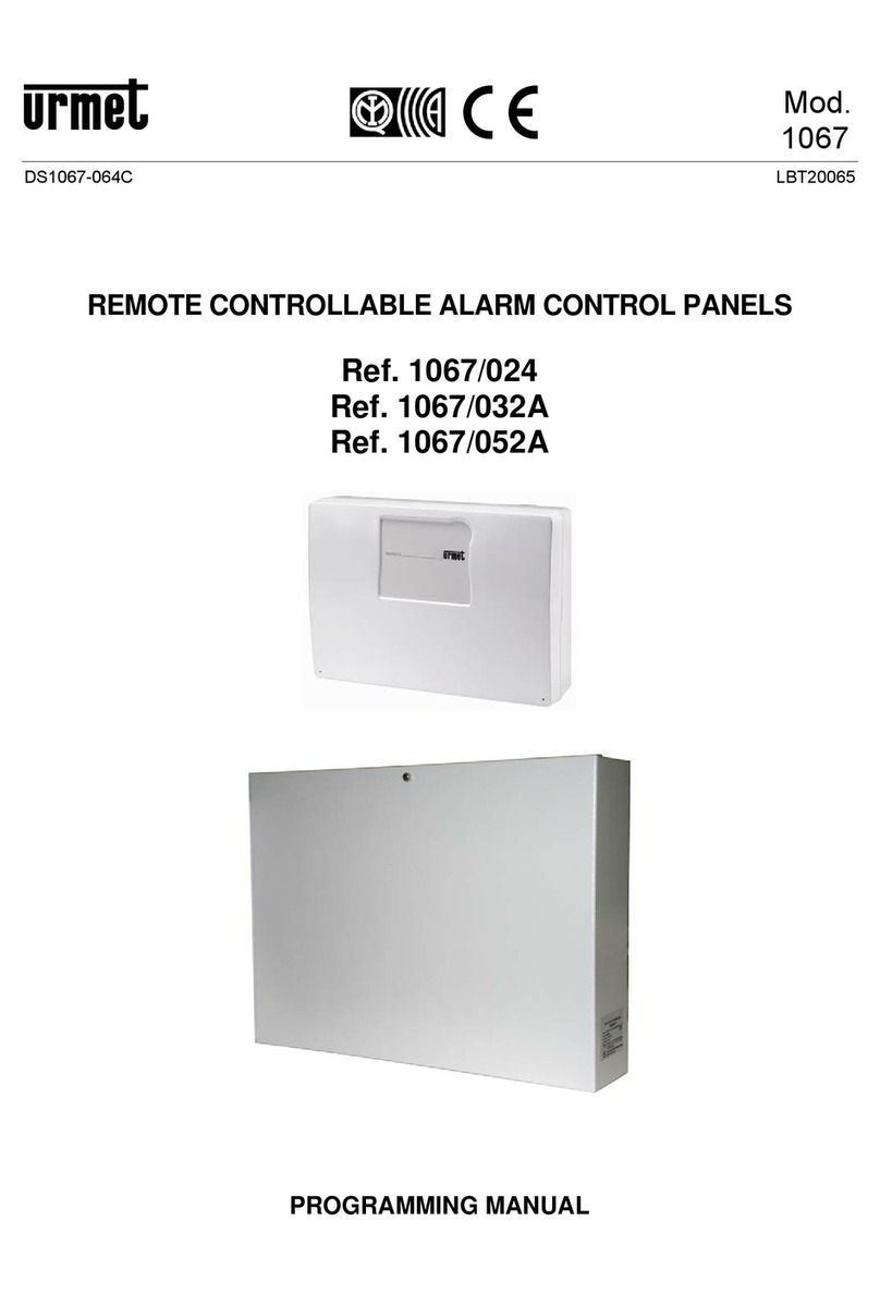
urmet domus 1067/032A User manual

DS1067-063D LBT20064
Mod.
1067
REMOTE CONTROLLABLE ALARM CONTROL PANELS
Ref. 1067/024
Ref. 1067/032A
Ref. 1067/052A
INSTALLATION MANUAL

DS1067-063D 2LBT20064
TABLE OF CONTENTS
PREFACE.......................................................................................................................................................... 6
Conformity with EN50131-1 ..................................................................................................................... 6
IMQ........................................................................................................................................................... 7
How the manual is organised................................................................................................................... 7
Conventions used..................................................................................................................................... 7
Glossary ................................................................................................................................................... 8
1THE 1067/024, 1067/032A AND 1067/052A SYSTEMS ......................................................................... 9
1.1 Main characteristics ..................................................................................................................... 9
1.2 System Architecture................................................................................................................... 10
1.2.1 Architecture........................................................................................................................................ 10
1.2.2 Bus Data ............................................................................................................................................ 10
1.2.3 Maximum system size........................................................................................................................ 11
1.3 System connectivity ................................................................................................................... 12
1.3.1 Connection with remote user.............................................................................................................. 13
1.3.2 Connection with a remote PC............................................................................................................. 14
1.3.3 Connection with a local PC ................................................................................................................ 15
1.3.4 Connection with an alarm reception centre........................................................................................ 16
1.4 System components .................................................................................................................. 17
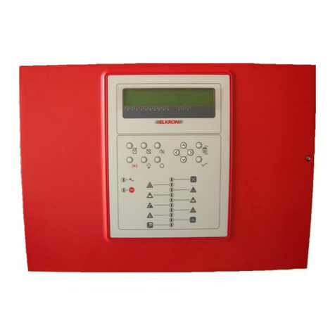
1.4.1 1067/024 Control panel...................................................................................................................... 17
1.4.2 1067/032A Control panel.................................................................................................................... 18
1.4.3 1067/052A Control panel.................................................................................................................... 19
1.4.4 1067/022 LCD Command Keypad ..................................................................................................... 20
1.4.5 1067/026 Touch Screen keypad ........................................................................................................ 20
1.4.6 1067/008A 8-inputs expansion module.............................................................................................. 21
1.4.7 Container for 1067/017 expansion module......................................................................................... 21
1.4.8 1067/334 -335 Electronic key reader.................................................................................................. 22
1.4.9 1067/332 Kit Additional keys.............................................................................................................. 22
1.4.10 1067/434 - 435 Proximity reader........................................................................................................ 23
1.4.11 1056/032 Kit proximity key................................................................................................................. 23
1.4.12 1067/092 supplemental power supply with repeater .......................................................................... 24
1.4.13 1067/012A –1067/012B Vocal voice synthesis module with handsfree earset.................................. 24
1.4.14 1067/002A PSTN Communicator....................................................................................................... 25
1.4.15 1067/458 GSM module ...................................................................................................................... 25
1.4.16 1067/014 Remote GSM antenna........................................................................................................ 25
1.4.17 1067/015 GSM antenna for metallic box (1067/052A)........................................................................ 26
1.4.18 1067/016 cable for keypad 1067/022................................................................................................. 26
1.4.19 1067/003 USB Interface..................................................................................................................... 26
1.4.20 1067/001 FastPro application software (rev. 2.40 or higher).............................................................. 27
1.4.21 1067/004 Web server interface .......................................................................................................... 27
2BASIC INFORMATION .......................................................................................................................... 28
2.1 How an intrusion alarm system is made.................................................................................... 28
2.1.1 The simplest system........................................................................................................................... 28
2.1.2 Wired, radio, and bus......................................................................................................................... 28
2.2 Communicating with the external environment.......................................................................... 29
2.3 The devices used to create an alarm system ............................................................................ 30
2.3.1 The control panel ............................................................................................................................... 30
2.3.2 The detectors..................................................................................................................................... 30
2.3.3 The signalling devices........................................................................................................................ 31
2.3.4 The complementary devices .............................................................................................................. 32
2.4 Other devices that can be integrated into the alarm system ..................................................... 33
3DESIGN: CONFIGURATION OF THE ALARM SYSTEM...................................................................... 34
3.1Identifying the grade of protection ............................................................................................. 34
3.2 The alarm system power supply................................................................................................ 34
3.3 How to design an alarm system................................................................................................. 35
3.3.1 Analysis of the site and needs............................................................................................................ 35
3.3.2 Certification requirements .................................................................................................................. 35
3.3.3 How to protect areas and people ....................................................................................................... 36

DS1067-063D 3LBT20064
3.3.4 The subdivision into zones................................................................................................................. 37
3.3.5 Choosing devices............................................................................................................................... 38
3.3.6 Positioning the system devices .......................................................................................................... 39
3.3.7 Tips about installing the radio devices................................................................................................ 40
3.3.8 Tips about the mobile phone network (GSM)..................................................................................... 41
3.4 Advanced functions.................................................................................................................... 41
3.4.1 The zones and the areas.................................................................................................................... 41
3.4.2 Input and output: select the delay to avoid setting off the alarm......................................................... 41
3.4.3 The complementary functions (gong, courtesy light, door opener, absence of move) ....................... 43
3.4.4 The attributes of the intrusion inputs (Release type, AND / OR zones, AND inputs).......................... 43
3.4.5 Remote activation of commandable outputs free of charge ............................................................... 44
3.4.6 Environmental listening...................................................................................................................... 44
4DESIGN: CALCULATIONS AND TESTS............................................................................................... 45
4.1 Sizing of the power supplies and the batteries.......................................................................... 45
4.1.1 Battery sizing...................................................................................................................................... 45
4.1.2 Calculation of the total absorption of the system................................................................................ 46
4.1.3 Using supplementary power supply units........................................................................................... 46
4.2 Cable Sizing............................................................................................................................... 46
4.2.1 Cables to be used, connections of the shields and installation .......................................................... 46
4.2.2 Sizing of the power supply cable........................................................................................................ 47
4.2.3 Sizing the power supply and data transmission bus........................................................................... 48
4.2.4 Extending the bus with the repeater................................................................................................... 48
4.2.5 Sizing of audio Bus............................................................................................................................. 50
4.2.6 Sizing of Input/Output connections..................................................................................................... 50
4.3 Control criteria of the mains power supply voltage.................................................................... 50
4.3.1 Blackout event.................................................................................................................................... 50
4.3.2 Continued blackout alarm................................................................................................................... 50
4.3.3 Restoration of the mains power supply .............................................................................................. 50
4.4 Battery management criteria...................................................................................................... 50
4.4.1 Control and charging of the battery with the mains power supply present ......................................... 50
4.4.2 Controlling the battery with mains power supply absent..................................................................... 51
4.4.3 Test battery........................................................................................................................................ 51
4.5 Self-diagnostic functions............................................................................................................ 51
5INSTALLATION...................................................................................................................................... 52
5.1 Installation procedure................................................................................................................. 52
5.2 Wiring......................................................................................................................................... 52
5.3 Preparing the 1067/024 - 1067/032A controlpanel...................................................................... 53
5.3.1 Opening the cover.............................................................................................................................. 53
5.3.2 Openings for cables ........................................................................................................................... 53
5.3.3 Fastening to the wall .......................................................................................................................... 54
5.3.4 Battery compartment and fastening points for the optional features in the 1067/024 - 1067/032A control
panel 55
5.3.5 Assembling expansion modules in the 1067/024 - 1067/032A control panel ..................................... 56
5.4 Preparing the 1067/052A control panel...................................................................................... 57
5.4.1 Opening the cover.............................................................................................................................. 57
5.4.2 Openings for cables ........................................................................................................................... 58
5.4.3 Fastening to the wall .......................................................................................................................... 58
5.4.4 Battery compartment and fastening points for the optional features in the 1067/052A control panel. 60
5.4.5 Assembling expansion modules in the 1067/052A control panel ....................................................... 60
5.5 Installing the 1067/024 –1067/032A –1067/052A control panels............................................ 61
5.5.1 Description of the main parts of the 1067/024 control panel .............................................................. 61
5.5.2 Description of the main parts of the 1067/032A –1067/052A control panels..................................... 63
5.5.3 Assembly of the 1067/002A PSTN Communicator............................................................................. 65
5.5.4 Montaggio Assembly of the 1067/012A - 1067/012B Vocal synthesis board ..................................... 66
5.5.5 Installation of the 1067/458 GSM module ......................................................................................... 67
5.6 Connection of the USB interface and web server...................................................................... 69
5.6.1 Temporary connection of the 1067/003 interface for the USB pen drive for connecting to the PC..... 69
5.6.2 Installation of the 1067/004 web server interface............................................................................... 70
5.7 Installation of the 1067/008A expansion.................................................................................... 71
5.8 Installation of the 1067/022 keypad........................................................................................... 72

DS1067-063D 4LBT20064
5.9 Installation of the 1067/026 touch screen keypad ..................................................................... 73
5.10 Installing the reader ................................................................................................................... 75
5.11 Installation of the 1067/092 supplementary power supply......................................................... 75
5.11.1 Fastening to the wall .......................................................................................................................... 75
5.11.2 Connecting the power supply and battery.......................................................................................... 76
5.11.3 The 1067/092 board........................................................................................................................... 77
5.12 Connections............................................................................................................................... 79
5.12.1 230 Vac power supply line ................................................................................................................. 79
5.12.2 Connecting the data Bus.................................................................................................................... 80
5.12.3 Connecting the audio Bus.................................................................................................................. 81
5.12.4 Connecting the supplementary power supplies/repeater.................................................................... 81
5.12.5 Connecting inputs............................................................................................................................... 83
5.12.6 Connecting outputs ............................................................................................................................ 85
5.12.7 Connecting the cable for KP SERVICE keypad ................................................................................. 87
5.12.8 Connecting the telephone dialler........................................................................................................ 87
5.13 Example of diagram with NC inputs 1067/024 CONTROL PANEL........................................... 89
5.14 Example of diagram with double bal. inputs 1067/024................................................................. 91
5.15 Example of diagram with NC inputs 1067/032A-1067/052A ..................................................... 93
5.16 Example of diagram with double bal. inputs 1067/032A-1067/052A............................................. 95
6COMMISSIONING.................................................................................................................................. 97
6.1 System power supply................................................................................................................. 97
6.1.1 RUN LED Indications ......................................................................................................................... 97
6.2 Acquisitions of bus devices........................................................................................................ 98
6.2.1 Position of the programming buttons.................................................................................................. 98
6.2.2 Procedure for acquiring bus devices.................................................................................................. 98
6.3 Using the service keypad........................................................................................................... 99
7MAINTENANCE ................................................................................................................................... 100
7.1 Maintenance procedure ........................................................................................................... 100
7.2 Addition and acquisition of a new device BUS ........................................................................ 100
7.3 Replacing a BUS device.......................................................................................................... 100
7.4 Identifying a BUS device.......................................................................................................... 101
7.4.1 Interrogating a bus device................................................................................................................ 101
7.4.2 Searching for a device...................................................................................................................... 101
7.5 Deleting a BUS device............................................................................................................. 101
7.5.1 Deleting a radio expansion............................................................................................................... 101
7.6 Acquisition / Maintenance of the radio devices........................................................................ 102
7.6.1 Radio connection test....................................................................................................................... 103
7.7 Configuring radio parameters .................................................................................................. 104
7.8 Deleting a radio device ............................................................................................................ 104
7.9 Resetting factory settings......................................................................................................... 105
7.9.1 Partial reset...................................................................................................................................... 105
7.9.2 Global reset...................................................................................................................................... 106
7.9.3 Resetting Installer, Tech. Manager, Master and User codes............................................................ 106
7.9.4 Resetting hardware installer code and Tech. Manager Code........................................................... 106
7.9.5 Resetting hardware to factory settings............................................................................................. 106
7.9.6 Resetting devices............................................................................................................................. 106
7.10 Replacing the battery............................................................................................................... 107
7.11 Turning off the entire system ................................................................................................... 107
7.12 Troubleshooting ....................................................................................................................... 108
8TECHNICAL SPECIFICATIONS.......................................................................................................... 111
8.1 1067/024 control panel ............................................................................................................ 111
8.2 1067/032A control panel.......................................................................................................... 112
8.3 1067/052A control panel.......................................................................................................... 113
8.4 1067/022 Keypad LDC display ................................................................................................ 114
8.5 1067/026 Keypad touch screen............................................................................................... 114

DS1067-063D 5LBT20064
8.6 1067/334 –1067/335 Electronic key reader............................................................................ 114
8.7 1067/434 –1067/435 –1067/436 Proximity reader ................................................................ 115
8.8 8-INPUT 1067/008A Expansion module.................................................................................. 115
8.9 1067/012A-1067/012B Vocal synthesis board......................................................................... 115
8.10 1067/002A PSTN COMMUNICATOR...................................................................................... 115
8.11 1067/458 GSM module............................................................................................................ 115
8.12 1067/003 USB interface........................................................................................................... 116
8.13 1067/004 Web server interface................................................................................................ 116
8.14 1067/092 Supplementary power unit with repeater................................................................. 117

DS1067-063D 6LBT20064
PREFACE
CONFORMITY WITH EN50131-1
The EN50131-1 standard calls for the installation of a grade four intruder alarm system, based on the level of risk
determined in function of the type of environments, of the value of the goods to be protected, and the typical intruder
expected.
Grade 1: Low risk
It is expected that the intruders have little knowledge of intrusion alarm systems and have a limited range of tools that
can be easily obtained. It is indicated for premises with contents of low value.
The system is simple and equipped with external and/or internal acoustic alarms, optical warnings, and eventually a
telephonic communicator to vocal messages to other people.
Grade 2: Average-low risk
It is expected that the intruders have limited knowledge of intruder alarm systems and use some tools and portable
instruments (for example, a multimeter).
It is the minimum level that can be recognised by insurance companies.
It involves mostly residential and commercial premises of low value.
The system can be connected with a Security Service.
Grade 3: Average-high risk
It is expected that the intruders have knowledge of intruder alarm systems and have a full range of tools and portable
electronic equipment.
It is indicated for commercial and industrial premises, as well as for residential premises with a high value.
The system is usually connected with a Security Service.
Grade 4: High risk
To be used when security has the priority over all other factors. It is expected that the intruders have the skills and
resources to plan a detailed intrusion and have a complete set of tools available, including the means for substituting
components of an intruder alarm system. This is indicated for particularly sensitive premises, for example, banks.
IMPORTANT! The grade of an intruder alarm system is the one of its lowest grade component.
The EN50131-1 standard requires that the components of the intruder alarm system are suitable to be used in one of the
following environmental classes, where Class I is the most moderate and class IV is the most severe.
Environmental class I –Indoors
Environmental influences normally present in closed environments, when the temperature is well-controlled (ex: in a
residential or commercial property).
NOTE: The environment should not be subject to condensation and the temperature should vary between +5°C and
+40°C with an average relative humidity of about 75%.
Environmental class II –Indoors –General
Environmental influences normally present in closed environments, when the temperature has not been controlled (ex: in
corridors, other spaces or stairways where condensation may form on windows and in unheated areas used as a deposit
or in warehouses where heating is intermittent).
NOTE: The environment should not be subject to condensation and the temperature should vary between -10°C and
+40°C with an average relative humidity of about 75%.
Environmental class III –Outdoors –Sheltered or indoors under extreme conditions
Environmental influences normally present outdoors when components of the intruder alarm system are not totally
exposed to atmospheric agents or indoors, when the environmental conditions are extreme.
NOTE: The environment should not be subject to condensation and the temperature should vary between -25°C and
+50°C with an average relative humidity of about 75%. For 30 days a year it is expected that the relative humidity will
vary between 85% and 95% without being subject to condensation.
Environmental class IV –Outdoors –General
Environmental influences normally present outdoors, when the components of the intruder alarm system are completely
exposed to the elements.
NOTE: The environment should not be subject to condensation and the temperature should vary between -25°C and
+60°C with an average relative humidity of about 75%. For 30 days a year it is expected that the relative humidity will
vary between 85% and 95% without being subject to condensation.
The 1067/024, 1067/032A and 1067/052A burglar alarm system was certified at IMQ - SECURITY SYSTEMS
laboratories in conformity with European standards EN 50131-1, EN 50131-3, and EN 50131-6 - Grade 2 or 3 -
Environmental class II - general indoors. The grade depends on how the system is constructed and/or configured.
With an ATS4 communicator connected, the 1067/032A and 1067/052A control panels, with 1067/002A Communicator,
respect notification options A and B –Grade 3.
With the telephone line connected, the 1067/024, 1067/032A and 1067/052A control panels, with 1067/002A
Communicator, can respect the notification options A and B - Grade 2.

DS1067-063D 7LBT20064
IMQ
IMQ is a Notified Organism, or a structure authorised by the national government authority and notified to the European
Commission. The Notified Organism is responsible for evaluating - with skill, transparency, neutrality, and independence
- the conformity of products and services with the conditions established by the European directives. These verifications
are carried out upon specific request of the economic operators, who pay all costs.
IMQ is the only Italian body that certifies security systems, attesting to the conformity of devices and components with
security specifications and performance contained in the relative CEI and EN standards. Moreover, it conducts the tests
required by other directives applicable to security systems, like those on electromagnetic emissions, on radio
frequencies, and radio communications.
HOW THE MANUAL IS ORGANISED
This manual is divided into chapters and the topics included are organised sequentially to accompany each phase, from
the system installation to its successive maintenance, step by step.
Chapter 1 describes the 1067/024, 1067/032A and 1067/052A, systems, their architecture and devices that may be part
of the systems.
Chapter 2 provides basic information about the alarm systems: how the alarm system is made, what it can do, the
components it is made of and how they work.
Chapter 3 explains how to design an alarm system using the 1067/024, 1067/032A and 1067/052A, control panels,
optimising all their potential.
Chapter 4 explains how to install the control panel, the devices, the accessories, and how to connect them all together.
Chapter 5 illustrates the preliminary operations to be carried out to start up the system, before its configuration (for the
configuration, see the Programming Manual).
Chapter 6 illustrates all the operations to be performed for starting up the alarm system, after having installed all the
devices and carried out all the required connections.
Chapter 7 illustrates all the maintenance activities necessary to keep the alarm system functioning with perfect efficiency
and provides troubleshooting advice.
Chapter 8 contains the technical specifications of the control panel and the various devices.
The description of the programming and configuration of the system are contained in the Programming Manual.
The descriptions the end user will need to use the system are contained in the User's Manual.
CONVENTIONS USED
This symbol signals an important warning.
This symbols signals a recommendation.
This symbol indicates the compatibility with EN50131 grade 3 certification.
The overall certification of the system is equal to the minimum certification of the devices installed and the
functions enabled.
This symbol indicates the compatibility with EN50131 grade 2 certification.
The overall certification of the system is equal to the minimum certification of the devices installed and the
functions enabled.
This symbol indicates that the compatibility with the EN50131 certification may depend on other functions
enabled in the system.
This symbol indicates that the function or the device are not certified according to Standard EN50131.
This symbol indicates that the function or the device invalidate the EN50131 certification.

DS1067-063D 8LBT20064
GLOSSARY
AND
A logical function that requires that all the terms of the operation be true in order for the result to be true.
Open
An input is open when it receives a signal from a detector that is no longer in stand-by, for
example, because of an attempted intrusion has been detected.
ATS
Acronym of Alarm Transmission System. Depending on the performances they are capable of
offering, they are classified from ATS 1 to ATS 6, where ATS 1 is the simplest system and ATS 6
is the system with the highest level of performance.
Communicator
A device capable of sending and transferring alarm signals and events via a telephone line.
Default
The initial value of a device before configuration or when it is restored to the values set by the
manufacturer.
DTMF
Dual Tone Multi Frequency, indicates the "tonal" mode of composition of a telephone.
Entry
A point of access to rooms protected by the anti-intrusion system.
Event
A fact that occurs accidentally or when a specific condition is met, for example when a certain
period of time has passed.
Physical address
Method used by the control panel to identify and locate inputs and outputs.
Logical address
An alternative addressing method by which the control panel displays inputs and outputs and
identifies them in the alarm messages. The addresses can be freely assigned by the user.
Input
A point (terminal block) for the physical connection of a detector (usually a sensor or a contact).
An input can be connected to multiple sensors, which are perceived as a single physical entity.
The input is defined as being open when the sensor signals that it is no longer in stand-by, for
example because it has verified an attempted intrusion.
OC
Open Collector transistor.
OR
A logical function that requires that at least one of the terms of operation be true for the result to be
true.
Way
A set of one or more inputs that temporarily inhibit the signalling of sensor alarms connected to
enable the entry into or exit of a protected zone. The duration of the temporary disabling is defined
as entry or exit time.
Protocol
Set of rules that govern the exchange or the transmission of data among devices.
PSTN
Public Switched Telephone Network indicates the telephone land line.
RM
Reset Memory, is a signal (voltage) control that provides to erase the memory of a detector and
that can inhibit its functioning, for example by putting it in stand-by.
SELV
Acronym for Safety Extra-Low Voltage (rated voltage max 25 Vca and 50 Vcc).
Zone
Grouping of entries, exits, user codes, and keys that are associated with a space to be controlled.
Tamper
Protective micro-contact of a device.
Entry time
The time that the user has available from the moment in which he opens the first input to
deactivate the desired zone/s and prevent the generation of an intrusion alarm by the inputs
configures as a "Way".
Delay time
The time that the user has available from the moment he opens the delayed input to the moment in
which the alarm is generated. It can be programmed for each individual input.
Exit time
The time that the user has available from the moment he activates the zone/s to exit the protected
area and prevent the generation of an intrusion alarm by the inputs configured as "Way".
Output
Point (terminal) for the physical connection of a device that enables the intrusion alarm system to
act in the external environment, e.g. by signalling an alarm (with a siren), communicating a system
status (with a warning light or an acoustic warning device), or activating electrical apparatus.
User
Grouping of one or more zones.

DS1067-063D 9LBT20064
1 THE 1067/024, 1067/032A AND 1067/052A SYSTEMS
This chapter illustrates the 1067/024, 1067/032A and 1067/052A. More specifically, the following are analysed:
the main characteristics of the systems;
the system architecture and the maximum dimension possible;
the connectivity of systems towards to outside;
the various devices and accessories that make up the systems.
1.1 MAIN CHARACTERISTICS
The 1067/024, 1067/032A and 1067/052A wired intrusion alarm systems are modular, suitable for small - mid-sized
systems in residential, industrial, and service settings.
The components and main functions of the system are certified Grade 3, according to EN50131 standards.
Keypads, readers and expansions are connected to the control panel microprocessor by a proprietary field bus.
Detectors, sirens, and other signals are instead connected to the inputs and outputs present in the control panels and in
other devices connected to the bus.
All the inputs can be configured for both type and specialisation.
The remote alarm notifications can be made with vocal message, text message, or numerical protocol (for the connection
to alarm reception units).
The system can be managed locally and remotely by means of a land line, cell phone, text message, and Internet.
Other functions available are:
Programming via PC equipped with FastPro software (2.30 or higher).
Saving of the program on a USB pen drive to transfer the program between PCs and control panel or save a
back-up copy.
Firmware device updates via USB interface with a pen drive.
Technological signalling, that are activated by an event other than intrusion. Following an event of this type, the
system can command even specific actuations.
Advanced vocal alarm calls, that allow specific alarm messages to be sent for individual zones and/or inputs.
Vocal message diffusion, system armed, system disarmed, system diagnostic information can be communicated
to user via hands-free vocal messages diffused by vocal keypad.
Service vocal message, the user may use any vocal keypad to issue a memo that will be reproduced locally until
the subsequent deactivation, by any vocal keypad
Remote ambient listening function, enables the user to hear, via telephone, to what is happening in the
environment, by addressing up to 8 listening points through the vocal keypads.
Vocal help for remote management, used by the system to guide the user with vocal messages.
Door opener, the electric lock can be controlled via the customized output, limiting access to specific areas only to
authorised personnel. Date, time and user who have commanded the opening are recorded in the control panel.
Telephonic activation of an output without a connection charge. By taking advantage of the GSM telephone
number recognition by the control panel, it is possible to generate a command on the specific output and close
communications after the first 3-4 rings without charging for the call.
Advanced automation. Through the timing programmer built into the control panel, it is possible to arrange a series
of automatic and repetitive commands weekly.
Moreover, there are two auxiliary functions that are not in conformity with current laws that allow the guaranteed security
of the system to be increased easily and economically, without however replacing the dedicated systems:
Emergency response signal, which generates service signals when a dedicated button is activated or no
movement is detected in the controlled environment.
Fire alarm, which generates service signals from part of the control panel when fire detectors managed by the same
are installed.
IMPORTANT! If the “emergency response call” is required, it is necessary to have a remote emergency response
system in conformity with current legislation on this topic.
To create a system that fully meets all the requirements of a fire detection system, consult Urmet’s general
catalogue in the Fire Prevention section.

DS1067-063D 10 LBT20064
1.2 SYSTEM ARCHITECTURE
1.2.1 Architecture
The diagram illustrates the devices and connections that can eventually be managed by the 1067/024, 1067/032A and
1067/052A. control panels. For the maximum dimensions the system can reach (combinations of devices and their
maximum number) see the paragraph 1.2.3 Maximum system size.
Figure 1 - System Architecture of the 1067/024, 1067/032A and 1067/052A
1.2.2 Bus Data
Control panel, keypads, readers, expansion modules and radio modules are interconnected by a 4-wire bus.
The 4 wires transmit information among the various devices and supply 12 Vdc power from the 1067/032A or 1067/052A
control panel to the keypad, readers, expansion modules, and radio modules.
The use of the bus noticeably simplifies the wiring, given that, for example, the information of a group of detectors
located far from the control panel and concentrated on a remote 1067/008A expansion module can be controlled with just
4 wires.
Note :
*1067/024 control panel= 4 inputs, 1 SAB input,
1 relè output, 1 electric output
** not available in the 1067/024 control panel
D
Web
1067/024
*
**
1067/012X vocal
Synthesis board
RadioExpans.
For details,
refer to the
dedicated
manual

DS1067-063D 11 LBT20064
1.2.3 Maximum system size
Table 1 illustrates the maximum number of keypads, readers, keys and expansion modules that can comprise the 1067
systems. For each device, the maximum individuals and combinations are indicated when the system comprises similar
devices.
For example, the table makes it possible to deduce that the maximum number of readers that can be installed is 32,
regardless if just one type or both types in the desired combination are used.
Device
1067/024 System
1067/032A System
1067/052A System
Max Number
of each type
Max Number
of mixed
combination
Max Number
of each type
Max Number
of mixed
combination
Max Number
of each type
Max Number
of mixed
combination
1067/022
Command keypad
4
4**
8
8**
8
8**
1067/026
Touch screen keypad
4
8
8
1067/008A
Expansion module
3
3(§)
7
7(§)
15
15(§)
Radio expansion
1
2
2
1067/092
supplemental power
supply with repeater
-
7
15
1067/334 –335
Electronic key reader
4
4
16
16
16
16
1067/434 –435
Transponder reader
4
16
16
1067/332
Electronic key
16
16
32
32
64
64
1056/032
Proximity key
16
32
64
Access Code *
16
-
32
-
64
-
*of which 1 Master, 1 Technician, and 1 Technical Manager.
** By using the Service Keypad, the max number is decreased by one unit: it becomes 3 in the 1067/024 control panel, 7
in the 1067/032A and 1067/052A control panels.
§- WARNING! The maximum number of the mixed combination must take into account the number of radio expansions.
Table 1 - Maximum system dimension 1067/024 - 1067/032A - 1067/052A
Table 2 illustrates the maximum number of wired inputs and outputs that a system can reach at its maximum expansion.
Type
1067/024 System
1067/032A System
1067/052A System
Max Number
Max Number
Max Number
Inputs for general use
32
64
128
Tamper inputs (SAB)
4
8
16
Relay outputs
4
9
17
Electrical outputs
7
18
34
Table 2 - Max number of wired inputs and outputs

DS1067-063D 12 LBT20064
1.3 SYSTEM CONNECTIVITY
The 1067/024, 1067/032A and 1067/052A systems can be connected to the external environment in different ways,
sending signals and receiving commands.
Possible connection methods are:
Public Switched Telephone Network (PSTN). Requires optional 1067/002A interface.
Mobile network (GSM). Requires optional 1067/458 interface.
USB. Requires optional 1067/003 interface.
Web Server: Requires optional 1067/004 interface.
The vocal function requires an optional 1067/012A-1067/012B interface.
The table below illustrates the functions available according to the means of communications used.
Description of information
transmitted or received
Means of communications used
PSTN
and GSM
(vocal)
GSM
(SMS)
PSTN and
GSM
(DTMF tones)
Web
Server
PSTN
(modem)
ATS
(IDP, ADF,
C200B,
C200B P-P)
Sent by the control panel
Signalling of the intrusion/tamper
alarm
■
■
■
■
■
Signalling of pre-alarm
■
■
Signalling of a technological event
■
■
■
■
■
Signal of panic/silent panic
/emergency response/hold-up
■
■
■
■
Signalling of arming/disarming of
system
■
■
■
■
Signalling of arming/disarming of
zone/s
■
■
■
■
Signalling of maintenance
■
■
Signalling of input isolation
■
■
Signalling of anomaly (black-out/
battery low/system breakdown)
■
■
■
■
Signalling of end of anomaly
■
■
Signally of a communications
breakdown(1)
■
■
Signalling of the end of a
communications breakdown
■
■
Signalling of the use of a false
code
■
■
SIM expiration notice
■
■
■
Send images to various alarms
■
Interaction with
the control panel
System arming/disarming
command
■
■
Command of arming/disarming of
zone/s
■
■
Video camera activation
command
■
Controlled output activation
command
■
■
Controlled output deactivation
command
■
■
Ambient listening arming
command
■
Input isolation/inclusion command
■
■
Read event log command
■
System status request
■
■
Note (1): Potential signalling is transmitted from the means of communication available not involved in the anomaly.

DS1067-063D 13 LBT20064
DISCLAIMER
Urmet S.p.A. declines any and all responsibility concerning the unavailability, temporary or permanent, of the PSTN
or GSM telephone network that may affect the making of calls or the sending or programmed messages.
Under conditions of a weak or disturbed field, there may be a decline in the performances of the GSM communication
vector.
Below are the various connections that can be managed by the 1067/032A or 1067/052A systems and the functions that
each one offers.
IMPORTANT! Some connections may require the installation of interfaces or other devices that invalidate the
EN50131 certification.
1.3.1 Connection with remote user
Figure 2 - Diagram of connection with remote user
From the control panel towards the remote user
The control panel, via outgoing calls, can:
Send alarms and vocal signals (PSTN and GSM).
Send alarms and signals via SMS (GSM).

DS1067-063D 14 LBT20064
From the remote user towards the control panel
The user, via calls to the control panel, can:
Use remote management with vocal guide and commands in DTMF for:
oinquiring about the system status (armed/disarmed, alarms, and anomalies present);
ozones activation and deactivation;
oisolation and resetting of inputs;
ooutput remote controls (for gate opening devices, heating equipment, irrigation, etc.);
oenvironment listening (through optional vocal keypads);
oenvironment speaking (through optional vocal keypads);
Remote management with SMS for output remote controls (forgate opening devices, heating equipment, irrigation, etc.);
“Zero cost” remote management through the Caller ID for output remote controls (gate opening devices, typically).
Notes:
The GSM 1067/458 interface is an optional item and can be used in control panel, either as an alternative or together
with the PSTN 1067/002A communicator.
As regards the GSM interface, using a SIM card (either of the pre-paid or the subscriber type) is sufficient; to avail of
the signalling for running out of credit, it is necessary to ascertain this service with the respective mobile phone
carrier.
For further information, please see 5.12.8 Connecting the telephone dialler.
1.3.2 Connection with a remote PC
Figure 3 - Diagram of connection with remote PC
Fixed telephone line
Analog
connection
Fixed telephone line
Analog
connection
ADSL
connection
1067/024
1067/024
1067/024

DS1067-063D 15 LBT20064
From the control panel towards the remote user
From the control panel, via outgoing calls, alarms and signals can be sent directly to the PC.
From the remote user towards the control panel
The user or installer, via calls to the control panel, or incoming calls to the control panel with return call, can:
Carry out remote programming.
Carry out remote management for:
oinquiring about the system status (armed/disarmed, alarms, and anomalies present);
ovisualization of the input status;
ozones activation and deactivation;
oisolation and resetting of inputs;
oenabling and disabling of codes and keys;
oevent log reading.
Notes:
The GSM 1067/458 interface is an optional item and can be used in control panels, either as an alternative or
together with the PSTN 1067/002A communicator.
In the GSM interface it is necessary to use a SIM card enabled for data/incoming fax + voice (the 1067 system was
tested with a TIM SIM)
The PC must have FastPro 1067/001 software installed.
For further information, please see 5.12.8 Connecting the telephone dialler.
1.3.3 Connection with a local PC
Figure 4 - Diagram of connection with local PC
With the USB and Web server interface, the same functions illustrated in paragraph 1.3.2 Connection with a remote PC
are available.
Notes:
The USB interface is generally used during maintenance to programme the control panel.
For connection USB, use the 1067/003 interface.
The PC must have FastPro 1067/001 software installed.

DS1067-063D 16 LBT20064
1.3.4 Connection with an alarm reception centre
Figure 5 - Diagram of connection with an alarm reception centre
With the traditional telephone network 1067/002A (PSTN) communicator, remote surveillance by an alarm reception
centre may be used.
The control panel sends alarms and signals to the centre using the IDP, ADF, or C200b protocols. The only certified
protocol is IDP.
For further information, please see 5.12.8 Connecting the telephone dialler.
Telephone
line
Numeric control panel
1067/024

DS1067-063D 17 LBT20064
1.4 SYSTEM COMPONENTS
1.4.1 1067/024 Control panel
Control panel with a programmable bus to control the system, capable of managing signals relative to intrusion,
sabotage, and technological events separately.
The control panel is equipped with:
4 inputs;
1 balanced SAB input;
2 outputs (1 relay output and 1 electric output);
1 switching power supply to provide power to internal circuits and devices;
internal seating for battery;
internal seating for 4 expansions;
The control panel manages up to 4 distinct zones.
Other characteristics of the control panel are:
protection against opening and removal;
saving of the last 1000 events;
management of a timing programmer.
The power supply of all the internal circuits and devices is provided by a 230 Vca –14.4 Vdc - 1.5 A switching power
supply; the use of a 12 V, 7.2 Ah battery backup is also provided.
Use batteries with UL 94 HB class inflammability or better.
The programming is carried out with a keypad through a simple tree menu available in 10 languages.
Otherwise, for greater convenience, the system can be programmed with a local PC, connected to the control panel via
the 1067/003 USB interface and with FastPro 1067/001 software (revision 2.40 or later).
The programming can be saved on a USB pen drive.
The functional capacities of the 1067/024 control panel can be increased with optional devices.
EN50131 Certification: Grade 2 - Class II.
IMPORTANT! For EN50131 certification is essential to use the 1067/002A PSTN Communicator.

DS1067-063D 18 LBT20064
1.4.2 1067/032A Control panel
Control panel with a programmable bus to control the system, capable of managing signals relative to intrusion,
sabotage, and technological events separately.
The control panel is equipped with:
8 inputs;
1 balanced SAB input;
6 outputs (2 relay output and 4 electric outputs);
1 switching power supply to provide power to internal circuits and devices;
internal seating for battery;
internal seating for 4 expansions.
The control panel manages up to 8 distinct zones.
Other characteristics of the control panel are:
protection against opening and removal;
saving of the last 1000 events;
extractable connector terminals to facilitate wiring;
management of a timing programmer.
The power supply of all the internal circuits and devices is provided by a 230 Vca - 14.4 Vdc - 1.5 A switching power
supply; the use of a 12 V, 7.2 Ah battery backup is also provided.
Use batteries with UL 94 HB class inflammability or better.
The programming is carried out with a keypad through a simple tree menu available in 10 languages.
Otherwise, for greater convenience, the system can be programmed with a local PC, connected to the control panel via
the 1067/003 USB interface and with FastPro 1067/001 software installed (revision 2.30 or later). The programming can
be saved on a USB pen drive.
The functional capacities of the 1067/032A control panel can be increased with optional devices.
EN50131 Certification: Grade 2 or Grade 3 - Class II.
IMPORTANT! For EN50131 certification is essential to use the 1067/002A PSTN Communicator.

DS1067-063D 19 LBT20064
1.4.3 1067/052A Control panel
Control panel with a programmable bus to control the system, capable of managing signals relative to intrusion,
sabotage, and technological events separately.
The control panel is equipped with:
8 inputs;
1 balanced SAB input;
6 outputs (2 relay output and 4 electric outputs);
1 switching power supply to provide power to internal circuits and devices;
internal seating for battery.
internal seating for 4 expansions
The control panel manages up to 16 distinct zones.
Other characteristics of the control panel are:
protection against opening and removal;
saving of the last 1000 events;
extractable connector terminals to facilitate wiring;
management of a timing programmer.
The power supply of all the internal circuits and devices is provided by a 230 Vac - 14.4 Vdc - 3.4 A switching power
supply; the use of a 12 V, 18 Ah battery backup is also provided.
Use batteries with UL 94 HB class inflammability or better.
The programming is carried out with a keypad through a simple tree menu available in 10 languages.
Otherwise, for greater convenience, the system can be programmed with a local PC, connected to the control panel via
the 1067/003 USB interface and with FastPro 1067/001 software installed (revision 2.30 or later). The programming can
be saved on a USB pen drive.
The functional capacities of the 1067/052A control panel can be increased with optional devices.
EN50131 Certification: Grade 2 or Grade 3 - Class II.
IMPORTANT! For EN50131 certification is essential to use the 1067/002A PSTN Communicator.

DS1067-063D 20 LBT20064
1.4.4 1067/022 LCD Command Keypad
Keypad with LCD display for interiors. Enables control and programming of the 1067/024, 1067/032A and 1067/052A
systems.
The keypad is equipped with:
LCD backlit display with 2x 16 characters with contrast and luminosity regulation;
9 LED to signal the system status;
12 alphanumerical keys;
7 browser keys;
buzzer with adjustable volume;
1 programmable input. The use of keypad input results in the loss of EN50131 certification;
environment listening microphone (by phone with PSTN or GSM interface).
The keypad is powered by the bus that connects it to the control panel.
EN50131 Certification: Grade 3 - Class II - Type A.
1.4.5 1067/026 Touch Screen keypad
Keypad with OLED display and soft-touch keys for interiors. Enables control and programming of the 1067/024,
1067/032A and 1067/052A systems.
The keypad is equipped with:
OLED technology graphic display with luminosity regulation;
signalling of the system status via graphic icons.
7 browser keys;
4 function keys;
12 alphanumerical keys;
4 signal LEDs;
buzzer with adjustable volume;
transponder reader for proximity keys;
1 programmable auxiliary input;
environmental listening function;
approach sensor.
The keypad is protected against opening and removal and is powered by the bus that connects it to the control panel.
EN50131 Certification: Grade 3 - Class II - Type B.
This manual suits for next models
2
Table of contents
Other urmet domus Control Panel manuals

urmet domus
urmet domus 1067 Series User manual

urmet domus
urmet domus 2 VOICE mikra User manual

urmet domus
urmet domus 1061/006A Assembly instructions

urmet domus
urmet domus ELKRON DK500M-P User manual

urmet domus
urmet domus 1083/12 User manual

urmet domus
urmet domus 1067 Series Owner's manual

urmet domus
urmet domus Elkron C420 User manual

urmet domus
urmet domus 1061/004 Assembly instructions

urmet domus
urmet domus 925 User manual

urmet domus
urmet domus 1067/032 Owner's manual