manuals.online logo
Brands
  1. Home
  2. •
  3. Brands
  4. •
  5. Watts
  6. •
  7. Control Unit
  8. •
  9. Watts POWERS HydroGuard LFG480 Series User manual

Watts POWERS HydroGuard LFG480 Series User manual

HydroGuard® Series LFG480 and LFE480
Lavatory Tempering Valve
Installation Instructions
IS-P-G480_E480
Approval n
Description n
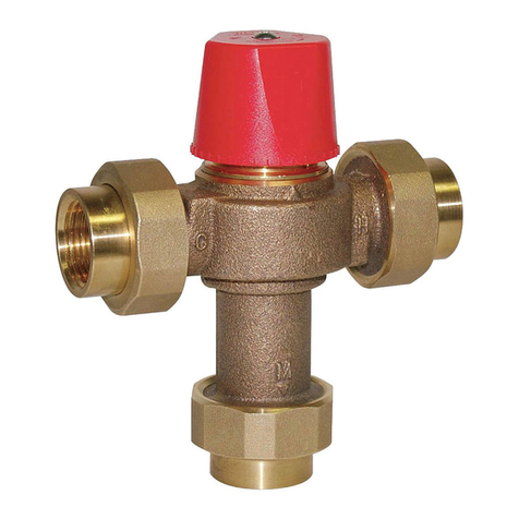
Powers Series LFG480 & LFE480 are designed for lavatory
applications where the temperature of the hot water must be
controlled for safe, economic use. An advanced thermal actua-
tor quickly senses and compensate for outlet temperature fluc-
tuations induced by water temperature and pressure changes in
the supply line.
Specifications n
Maximum Operating Pressure: ............................ 125psi (861 kpa)
Maximum Hot Water Temperature: ........................... 180°F (82°C)
Minimum Hot Water Supply Temp.: .... 5°F (3°C) Above Set Point**
Hot Water Inlet Temperature Range: ......... 120 – 180°F (49-82°C)
Cold Water Inlet Temperature Range: .............. 40 – 80°F (4-27°C)
Temperature Adjustment Range: ................. 80 – 120°F (27-49°C)
Minimum Flow:
LFG480 .................................................. 0.25 gpm (1.0 lpm)
LFE480 .................................................. 0.50 gpm (1.9 lpm)
Listing: ................. ASSE 1070, IAPMO cUPC, and NSF 61-9 & 372
** With Equal Pressure
Flow Capacity n
LFE480-00Q LFE480-10Q
WARNING
!
Read this Manual BEFORE using this equipment.
Failure to read and follow all safety and use infor-
mation can result in death, serious personal injury,
property damage, or damage to the equipment.
Keep this Manual for future reference.
You are required to consult the local building and plumbing
codes prior to installation. If the information in this manual is
not consistent with local building or plumbing codes, the local
codes should be followed. Inquire with governing authorities
for additional local requirements.
WARNING
!
FAILURE TO COMPLY WITH PROPER INSTALLATION AND
MAINTENANCE INSTRUCTIONS COULD CONTRIBUTE TO
THE VALVE FAILURE, RESULTING IN INJURY AND/OR
DEATH.
TO ENSURE THE ACCURATE AND RELIABLE OPERATION OF
THIS PRODUCT, IT IS ESSENTIAL TO:
• Properly design the system to minimize pressure and
temperature variations.
• This valve is factory preset. However, it can be adjusted
to deliver scalding temperatures. Check outlet tem-
perature to ensure it does not exceed 105°F (41°C).
Make sure temperature limit stop is properly re-set to
maximum 105°F (41°C) following valve maintenance or
repair. Tampering with limit stop in any way may result
in scalding temperature causing serious bodily harm and/
or death.
WARNING
!
WARNING
!
Need for Periodic Inspection and Yearly Maintenance:
Periodic inspection and yearly maintenance by a licensed con-
tractor is required. Corrosive water conditions, inlet temperatures
over 200°F (93°C), and/or unauthorized adjustments or repair
could render the valve ineffective for service intended. Regular
checking and cleaning of the valve’s internal components and
check stops helps assure maximum life and proper product
function. Frequency of cleaning and inspection depends upon
local water conditions.
PSI
G
P
M
0 10 20 30 40 50 60 70 80 90 100
7
6
5
4
3
2
1
0
E480
G480
Certified to
NSF/ANSI/CAN 61-9 & 372
ASSE 1070
This product meets the reduced Q test statistic criteria of
0.5 ppb for lead per Section 9.5.1.1 of NSF/ANSI/CAN 61.
Temperature Adjustment n
1. Loosen locknut.
2. Turn on fixture and run water for at least two minutes to allow
supply temperature to stabilize.
3. Turn temperature stem counter-clockwise for hotter or
clockwise for colder outlet temperature.
4. Tighten locknut to prevent accidental or unauthorized
temperature adjustment.
5. Re-check outlet temperature.
Repair Kit n
Motor Repair Kit: ................................................................ 480 270
To Install n
1. Installation should be in accordance with acceptable plumb-
ing practices. Flush all piping thoroughly before installation.
Installation and field adjustment are the responsibility of the
installer.
2. Locate suitable place for the tempering valve. Valve should
be accessible for service and adjustment and as close to
the point-of-use as possible.
3. Connect hot and cold supplies to valve and outlet of tem-
pering valve to fixture (s) using 1/2" or 3/8" compression
connections.
4. Turn on hot and cold water supplies. If any leaks are
observed, tighten connections as necessary to stop leaks
before proceeding.
5. Turn on fixture and allow water to flow for 2 minutes.
Measure water temperature at the outlet. If water is not at
desired temperature, adjust as necessary (see temperature
adjustment section). Maximum outlet temperature of 105°F
(41°C) is recommended.
Typical Installation
IS-P-G480_E480 2351 EDP#6512252 © 2023 Powers
USA: T: (888) 432-8932 • PowersControls.com
Canada: T: (888) 208-8927 • PowersControls.ca
Latin America: T: (52) 55-4122-0138 • PowersControls.com
Warranty n
The Seller warrants that the equipment manufactured by it and covered by this order or contract is free from defects in material and workmanship and, without charge, equipment found to be defec-
tive in material or workmanship will be repaired, or at Seller’s option replaced F.O.B. original point of shipment, if written notice of failure is received by Seller within one (1) year after date of shipment
(unless specifically noted elsewhere), provided said equipment has been properly installed, operated in accordance with the Seller’s instructions, and provided such defects are not due to abuse or
decomposition by chemical or galvanic action. THIS EXPRESS WARRANTY IS IN LIEU OF AND EXCLUDES ALL OTHER WARRANTIES, GUARANTEES, OR REPRESENTATIONS, EXPRESS OF IMPLIED.
THERE ARE NO IMPLIED WARRANTIES OF MERCHANTABILITY OR OF FITNESS FOR A PARTICULAR PURPOSE. The Seller assumes no responsibility for repairs made on the Seller’s equipment unless
done by the Seller’s authorized personnel, or by written authority from the Seller. The Seller makes no guarantee with respect to material not manufactured by it.
WARNING: This product contains chemicals known
to the State of California to cause cancer and birth
defects or other reproductive harm.
For more information: www.watts.com/prop65

This manual suits for next models

3

Other Watts Control Unit manuals

Watts AMES 950GD Installation and operating instructions

Watts

Watts AMES 950GD Installation and operating instructions

Watts FP-53L-M1 User manual

Watts

Watts FP-53L-M1 User manual

Watts 007 Series Instruction Manual

Watts

Watts 007 Series Instruction Manual

Watts 972GD-20 User manual

Watts

Watts 972GD-20 User manual

Watts AMES 979GD-20 Installation and operating instructions

Watts

Watts AMES 979GD-20 Installation and operating instructions

Watts LFM116-31 Owner's manual

Watts

Watts LFM116-31 Owner's manual

Watts 2300 Series User manual

Watts

Watts 2300 Series User manual

Watts EVO Series User manual

Watts

Watts EVO Series User manual

Watts LFM115-4 Owner's manual

Watts

Watts LFM115-4 Owner's manual

Watts LFM110-18 User manual

Watts

Watts LFM110-18 User manual

Watts LF25AUB-Z3 Series Setup guide

Watts

Watts LF25AUB-Z3 Series Setup guide

Watts Ames 912GD-01 Owner's manual

Watts

Watts Ames 912GD-01 Owner's manual

Watts LFMMV Series User manual

Watts

Watts LFMMV Series User manual

Watts 9DS Series User manual

Watts

Watts 9DS Series User manual

Watts Tekmar 305V User manual

Watts

Watts Tekmar 305V User manual

Watts LFM113-21 Guide

Watts

Watts LFM113-21 Guide

Watts LFUSG-B-M1 User manual

Watts

Watts LFUSG-B-M1 User manual

Watts LFM115-7 Owner's manual

Watts

Watts LFM115-7 Owner's manual

Watts bar-positrol Service manual

Watts

Watts bar-positrol Service manual

Watts FEBCO 860 Small Series Operating instructions

Watts

Watts FEBCO 860 Small Series Operating instructions

Watts AMES 2000SS Series Operating instructions

Watts

Watts AMES 2000SS Series Operating instructions

Watts bar PZDS Operational manual

Watts

Watts bar PZDS Operational manual

Watts LFM127-32 Installation and operating instructions

Watts

Watts LFM127-32 Installation and operating instructions

Watts LFM513-6 Installation and operating instructions

Watts

Watts LFM513-6 Installation and operating instructions

Popular Control Unit manuals by other brands

Marecoluce Tetris Solar manual

Marecoluce

Marecoluce Tetris Solar manual

DUKER 451 operating instructions

DUKER

DUKER 451 operating instructions

Flight Systems SCU 9iS Installation & operation manual

Flight Systems

Flight Systems SCU 9iS Installation & operation manual

Genebre 2120 Installation, operation and maintenance manual

Genebre

Genebre 2120 Installation, operation and maintenance manual

Bauhn HE214036 instruction manual

Bauhn

Bauhn HE214036 instruction manual

Kemper 689 04 025 Service manual

Kemper

Kemper 689 04 025 Service manual

Fluidmaster 400A Quick install guide

Fluidmaster

Fluidmaster 400A Quick install guide

Aaeon COM-TGUC6 user manual

Aaeon

Aaeon COM-TGUC6 user manual

DeDietrich AD249 Assembly instructions

DeDietrich

DeDietrich AD249 Assembly instructions

Hayward HCV20715 owner's manual

Hayward

Hayward HCV20715 owner's manual

National Instruments NI 9474 Getting started guide

National Instruments

National Instruments NI 9474 Getting started guide

Woodward easYgen 3000XT Series Option manual

Woodward

Woodward easYgen 3000XT Series Option manual

Analog Devices Linear Technology DC2268A-C Demo Manual

Analog Devices

Analog Devices Linear Technology DC2268A-C Demo Manual

Siemens Simatic S7-1500 manual

Siemens

Siemens Simatic S7-1500 manual

Victaulic 725S Series Installation and operating instructions

Victaulic

Victaulic 725S Series Installation and operating instructions

Wetronic MS16 manual

Wetronic

Wetronic MS16 manual

Fenwal Controls 05-50 Series manual

Fenwal Controls

Fenwal Controls 05-50 Series manual

Enerpac VM43-LPS Repair Parts Sheet

Enerpac

Enerpac VM43-LPS Repair Parts Sheet

manuals.online logo
manuals.online logoBrands
  • About & Mission
  • Contact us
  • Privacy Policy
  • Terms and Conditions

Copyright 2025 Manuals.Online. All Rights Reserved.