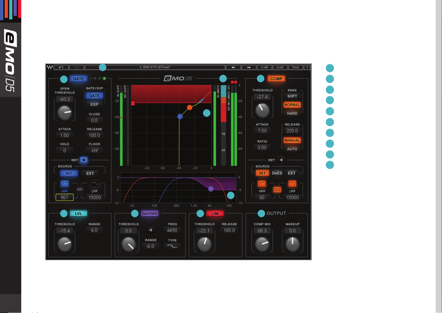
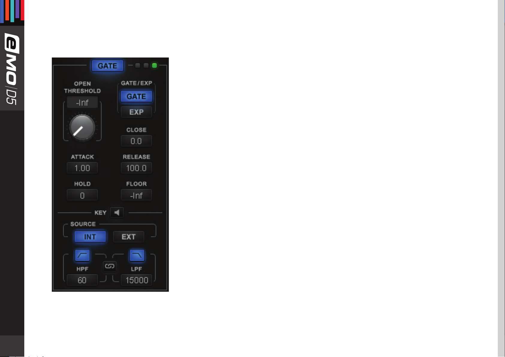
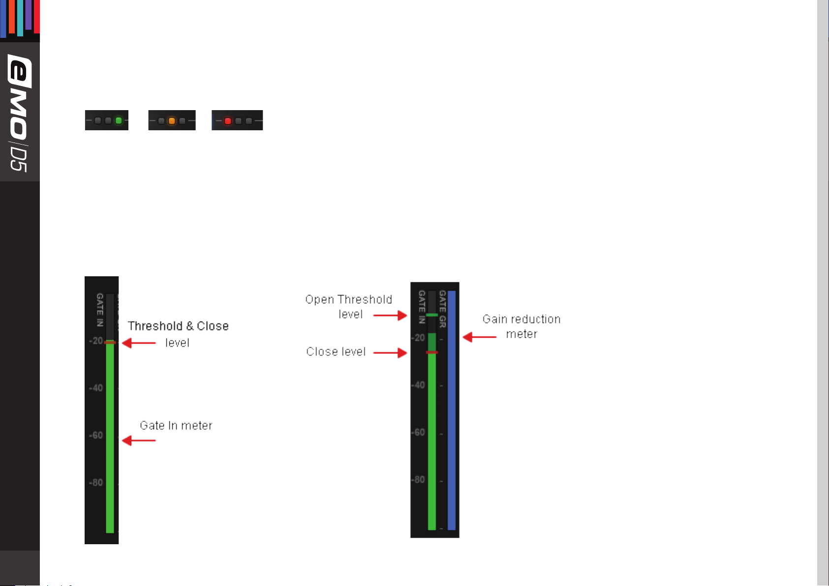
Waves EMO D5 User manual

user guide

Table of ContentsContents
Chapter 1: Introduction.......................................................................................................................................................................3
1.1 Welcome .........................................................................................................................................................................................3
1.2 Product Overview ....................................................................................................................................................................................3
1.3
Components..............................................................................................................................................................................................4
Chapter 2: Quick Start Guide.............................................................................................................................................................5
Chapter 3: Interface and Controls..................................................................................................................................................................6
3.1 Interface ........................................................................................................................................................................................6
3.2 Gate Section ................................................................................................................................................................................7
3.3 Compressor Section...............................................................................................................................................................................11
3.4 Leveler Section ......................................................................................................................................................................... 15
3.5 DeEsser Section........................................................................................................................................................................ 17
3.6 Limiter Section.......................................................................................................................................................................... 19
3.7 Other Meters and Controls................................................................................................................................................... 20
3.8 eMo-D5 Block Diagram.......................................................................................................................................................... 21

3
Chapter 1:introduCtion
1.1 Welcome
Thank you for choosing Waves! In order to get the most out of your new Waves plugin, please take a moment to read this user
guide.
To install software and manage your licenses, you need to have a free Waves account. Sign up at www.waves.com. With a Waves
account you can keep track of your products, renew your Waves Update Plan, participate in bonus programs, and keep up to date
with important information.
We suggest that you become familiar with the Waves Support pages: www.waves.com/support. There are technical articles about
installation, troubleshooting, specifications, and more. Plus, you’ll find company contact information and Waves Support news.
1.2 Product Overview
The eMo-D5 plugin is an advanced yet easy-to-use dynamics multiprocessor that delivers the power of five plugins in one
interface. It gives you maximum versatility for shaping the dynamics of any signal, with zero latency and very low CPU
consumption.
eMo-D5 processors:
1. Gate with dedicated HP/LP lters and an external sidechain option
2. Compressor with a parallel compression feature, dedicated high-pass/low-pass lters and an external sidechain option
3. C-weighted Leveler with adjustable range
4. Comprehensive DeEsser with pre/post-compressor routing and 3 lter types
5. Smooth, sharp-attack Limiter with zero latency
To help you easily control and monitor the total dynamic change added by the dierent processors, eMo-D5 employs clever parallel
detection and adds a combined gain reduction meter for the Leveler, Compressor and Limiter.

4
The eMo-D5 plugin was made with live engineers in mind. This is reected in the plugin’s zero latency and low CPU performance.
While these qualities are especially important in live situations, they are also signicant and useful in studio applications.
eMo-D5 is built for touch. All controls are large and touchscreen-friendly, and the workow is adapted for smooth, convenient work
on touchscreen interfaces.
1.3 Components
WaveShell technology enables us to split Waves processors into smaller plugins, which we call components. Having a choice of com-
ponents for a particular processor gives you the exibility to choose the conguration best suited to your material.
The eMo-D5 plugin includes the following components:
• eMo-D5 Mono
• eMo-D5 Stereo

5
Chapter 2: QuiCk start guide
Use the WaveSystem toolbar at the top of the plugin to save and load presets, compare settings, undo and redo steps, and resize
the plugin.
As with all Waves plugins, factory presets are a good place to start. Click the Presets button on the WaveSystem toolbar, and
choose the preset closest to the source audio you are working with. Tweak it from there.
Alternatively, you can start from scratch. To get going, turn on the desired dynamic section and play with the threshold knob to
achieve the desired effect.
You can always reset all plugin controls by loading the eMo-D5 Full Reset preset, using the Presets button.
To learn more, click the icon at the upper-right corner of the window and open the WaveSystem Guide.

6
Chapter 3: interfaCe and Controls
3 .1 I n t e r f a c e
1
2
3
4
5
6
7
8
9
10
WaveSystem Toolbar
Gate
Compressor
Leveler
DeEsser
Limiter
Output
Filter Graph
Input/Output Graph
Combined Gain
Reduction Meter
5
10
4
9
3
8
2
7
1
6

7
3.2 Gate Section
Controls
GATE: Turns on or bypasses the Gate section.
Range: On, O
Default: O
GATE/EXP: Toggles between Gate and Expander modes.
Gate mode provides sharper results, basically muting all
audio below the Threshold level.
Expander mode provides more natural results, never muting the audio. The Gate is never
completely closed, providing“softer” gating.
Additional Gate controls allow natural results even in Gate mode.
Range: GATE, EXP
Default: GATE
OPEN THRESHOLD: Sets the Gate Open level.
Range: -Inf to 0 db
Default: -Inf
CLOSE: Allows independent adjustment for the Gate Close level.
Range: -48 to 0 db
Default: 0 db
FLOOR: Adjusts the level of maximum gain reduction.
Range: -Inf to 0 db
Default: -Inf
ATTACK: Determines how quickly the Gate opens.
Range: 0.1 to 100 ms
Default: 1 ms

8
HOLD: Sets how long the Gate will stay open even if the signal falls below Threshold.
Range: 0 to 10000 ms
Default: 0 ms
RELEASE: Sets how fast the Gate closes (fades out) after the signal falls below Threshold.
Range: 1 to 1000 ms
Default: 100 ms
KEY: Lets you choose, lter and audition the sidechain source.
The Key feature adds additional precision in controlling dynamics.
The Key acts as a trigger that activates the dynamic process.
It can be Internal (INT) – triggered by its own signal, or External (EXT) – triggered by another
audio channel through sidechain routing, in which case the external signal is routed
independently as a sidechain input to the Gate.
Range: INT, EXT
Default: INT
In addition, the Key signal (whether INT or EXT) can be ltered using HP/LP lters.
HPF Range: 16 to 18000 Hz
Default: 60 Hz
LPF Range: 16 to 18000 Hz
Default: 15000 Hz
To link HPF and LPF, hit the Filter Link
Filter Link Range: On, O
Default: O
To audition Key signals, hit the Preview. The auditioned audio will be aected by Filters state, but unaected dynamically.
Range: On, O
Default: O

9
Meters and Indicators
Gate state LEDs
Green = Open, Yellow = Hold, Red = Close
GATE IN meter
Shows input level. When Key is in EXT, the meter will show the input level of the external sidechain. A single red marker on the Gate
In meter indicates the Gate Threshold and Close levels. You can set the Gate Close level independently of Gate Threshold, in which
case the Close marker will stay red, while the Threshold marker will become green.
GATE GR Meter
Shows the amount of attenuation introduced by the Gate section.
This attenuation is not reected in the Combined Gain Reduction Meter.

10
Input/Output Graph
Indicates Gates Range and Open Threshold levels.
The Open Threshold level can be adjusted by dragging the blue dot.
Gate Key Filters: shown in the Filter Graph as blue curves.

11
3.3 Compressor Section
Controls
COMP: Turns on or bypasses the Compressor section.
Range: On, O
Default: O
KNEE: Sets how aggressively the Compressor reacts to the signal.
Range: SOFT, NORMAL, HARD
Default: NORMAL
THRESHOLD: Sets the Compressor’s engagement level.
Range: -48 to 0 db
Default: 0 db
RATIO: Determines how hard the signal is compressed.
Range: 1 to 20
Default: 3
ATTACK: Determines how quickly the Compressor reacts to a signal.
Range: 0.5 to 300 ms
Default: 7 ms
RELEASE: Determines how fast the Compressor reduces processing after the signal falls
below the Threshold. When in Manual mode, the release time is set by the Release Value.
When in Auto mode, the release time adjusts automatically within the range set by the
Release Value.
Release modes: AUTO, MANUAL
Default: MANUAL
Release time range: 1 to 3000 ms
Default: 220 ms

12
KEY: Lets you choose, lter and preview DeEsser and Compressor routing or external sidechain source.
The Key feature adds additional precision in controlling dynamics. The Key acts as a trigger that
activates the dynamic process. The Key can be internal – triggered by its own signal, or External
– triggered by another audio channel through sidechain routing to the Compressor.
The Compressor has two internal routing options:
• INT: Compressor triggered by its own signal; DeEsser routed post-Compressor
• DeES: DeEsser routed pre-Compressor
Range: INT, DeES, EXT
Default: INT
In addition, the Key signal (whether internal or external) can be ltered using HP/LP lters.
HPF Range: 16 to 18000 Hz
Default: 60 Hz
LPF Range: 16 to 18000 Hz
Default: 15000 Hz
To link HPF and LPF, hit the Filter Link.
Filter Link Range: On, O
Default: O
To audition the Key signals, hit the Preview. The auditioned audio will be aected by Filters state, but unaected
dynamically.
Range: On, O
Default: O
COMP MIX (located in the OUTPUT section): Allows parallel compression by mixing the compressed and the
uncompressed audio.
Range: 0 (= uncompressed audio) to 100 (= compressed audio)
Default: 100

13
Meters and Indicators
COMP IN Meter:
Shows the input level. When Key is in EXT, the meter will show the input level of the External Key.
LVL COMP LIM GR Meter:
Combined gain reduction meter for the Leveler, Compressor and Limiter. The amount of gain reduction introduced by the
Compressor is shown in orange.
Input/Output Graph:
Indicates the Compressor’s Threshold level, Knee and Ratio. Threshold level can be adjusted by dragging the orange dot.

14
Filter Graph:
Shows the Compressor's Key lters in orange.

15
3.4 Leveler Section
A leveler is used to maintain constant levels over long segments of audio. Essentially, a leveler is a compressor set to very long attack
and release times. A leveler can also be viewed as an RMS compressor. The leveler smoothly and transparently gain-rides any signal
that exceeds its threshold, bringing it back down as close as possible to the desired target level (the threshold).
Controls
LVL: Turns on or bypasses the Leveler section.
Range: On, O
Default: O
THRESHOLD: Sets both the threshold above which leveling is applied and the target to
which the audio
signal is leveled.
Range: -48 to 0 db
Default: 0 db
RANGE: Sets the range of the Leveler’s processing.
Range: 0 to 48 db
Default: 6 db

16
Meters and Indicators
Input/Output Graph:
Shows the Leveler’s range
and threshold/target levels. Leveler shown as a light
blue line.
LVL COMP LIM GR Meter:
Combined gain reduction
meter for the Leveler, the Compressor and the Limiter.
The amount of gain reduction introduced by the Leveler is shown in light blue.

17
3.5 DeEsser Section
Controls
DeESSER: Turns on or bypasses the
DeEsser section.
Range: On, O
Default: O
THRESHOLD: Sets the DeEsser’s engagement level.
The DeEsser’s threshold uses adaptive sensing to provide more natural results.
Range: -48 to 0 db
Default: 0 db
TYPE: Sets the band type – high-pass or band-pass lter.
Range: Shelf Bell Notch
Default: Shelf
FREQ: Sets the roll-o start point for a high-pass lter or the center frequency for the band-pass lter.
Range: 16 to 21357 Hz
Default: 4490 Hz
RANGE: Sets the amplitude of the DeEsser’s processing.
Range: -12 to 0 db
Default: -6 db
PREVIEW: Lets you audition the DeEsser’s lter.
Range: On, O
Default: O

18
Meters and Indicators
Filter Graph:
Shows the DeEsser’s type, frequency, range and DS gain reduction in purple.
Frequency and range can be adjusted by dragging the purple dot.
Note: The DeEsser’s attenuation is not reected in the Combined Gain Reduction Meter.

19
3.6 Limiter Section
Controls
LIM: Turns on or bypasses the Limiter section.
Range: On, O
Default: O
THRESHOLD: Sets engage level for Limiter.
Range: -48 to 0 db
Default: 0 db
RELEASE: Sets how fast the Limiter reduces the processing after the signal falls below the
Threshold. This function utilizes adaptive technology, which means that release time adjusts
automatically to the Release range value.
Range: 0.1 to 1000 ms
Default: 100 ms
Meters and Indicators
Input/Output Graph:
Shows the Limiter’s Threshold level.
Limiter shown as a horizontal red line.
LVL COMP LIM GR Meter:
The Limiter’s gain reduction meter.
Shows the amount of attenuation
introduced
by the Limiter in red.

20
3.7 Other Meters and Controls
Makeup Gain
The Makeup Gain control is used to compensate for the gain reduction introduced by the multiple dynamic tools.
Make sure you don't clip the Output meter when boosting Makeup Gain.
Range: -18 to 18 db
Default: 0 db
Combined Gain Reduction Meter
The Combined Gain Reduction
Meter shows in one unied view
the gain reduction introduced by
the Leveler, the Compressor,
and the Limiter.
This meter does not reect the
gain reduction introduced by the
DeEsser and the Gate.
Output Meter
The Output meter shows the nal
output level produced by eMo-D5
You see a single meter for the Mono
component, two meters (Left and
Right) for the Stereo component.
The Output meter features the Peak
Led as well.
Table of contents
Other Waves Recording Equipment manuals

Waves
Waves NLS User manual

Waves
Waves CLA EFFECTS User manual

Waves
Waves VOCAL RIDER User manual

Waves
Waves Maserati B72 User manual

Waves
Waves dspro STAGERGRID 4000 User manual

Waves
Waves BASS RIDER User manual

Waves
Waves Roland XI-WSG User manual

Waves
Waves DiGiGrid IOC User manual

Waves
Waves ELEMENT 2.0 User manual

Waves
Waves MIDIPLUS FIT User manual

Waves
Waves JJP User manual

Waves
Waves DiGiGrid MGB User manual

Waves
Waves DSPro StageGrid 4000 User manual

Waves
Waves IONIC 16 User manual

Waves
Waves API 560 User manual

Waves
Waves ABBEY ROAD J37 User manual

Waves
Waves CA1000 User manual

Waves
Waves Abbey Road Vinyl User manual

Waves
Waves DiGoGrid IOX User manual

Waves
Waves DiGiGrid MGR User manual