manuals.online logo
Brands
  1. Home
  2. •
  3. Brands
  4. •
  5. Festo
  6. •
  7. Recording Equipment
  8. •
  9. Festo CPX-CTEL-2-M12-5POL-LK User manual

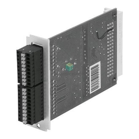
Festo CPX-CTEL-2-M12-5POL-LK User manual

Electrical interface
CPX-CTEL-2-M12-5POL-LK
Festo SE & Co.
KG Ruiter Straße
82 73734
Esslingen
Germany
+49 711 347-0
www.festo.com
Brief description
Translation of the original instructions
8101617
2018-11a
[8101619]
Electrical interface CPX-CTEL-2-M12-5POL-LK English......................
For all available product documentation èwww.festo.com/pk
1 Intended use
The module described in this document provides 2 outward interfaces to connect
devices with IO-Link interface (devices).
The module is intended for use in an industrial environment. Outside of industrial
environments, e.g. in commercial and mixed-residential areas, actions to suppress
interference may have to be taken.
The module is intended exclusively for use in CPX terminals from Festo for installa
tion in machines or automated systems and may be used only in the following
ways:
– in perfect technical condition
– in original status without unauthorised modifications, except for the adapta
tions described in this documentation
– within the limits of the product defined through the technical data.
IO-Link®is a registered trademark of its respective trademark holder in
certain countries.
2 Security
This documentation is directed exclusively toward technicians trained in control
and automation technology.
You can find detailed information in the description for the module
(P.BE-CPX-CTEL-2-M12-5POL-LK-…) as well as in the CPX system
description (P.BE-CPX-SYS-…).
Warning
Electric shock
Injury to people, damage to the machine and system
 For the electrical power supply, use only PELV circuits in accordance with
IEC 60204-1 (Protective Extra-Low Voltage, PELV).
 Observe the general requirements of IEC 60204-1 for PELV circuits.
 Use only voltage sources that guarantee a reliable electrical disconnection of
operating and load voltage in accordance with IEC 60204-1.
 Always connect all circuits for operating and load voltage supplies UEL/SEN,
UVAL and UOUT.
Note
Electrostatically sensitive devices
 Do not touch any components.
 Observe the handling specifications for electrostatically sensitive
devices.
Note
 Take into account the specifications and notes in the description of the mod
ule and mounting instructions of the components.
 Commission the module only if fully mounted and wired.
3 Connections and displays
1
2
34
5
1Rating plate
2CPX-specific LEDs
3X3 and X41)
4Port 1 and port 22)
5Status LEDs for port 1 and port 2
1) Equip with protective cap (without function) 2) Connector socket: M12, A-coded, 5-pin
Fig. 1
3.1 Interfaces
Port Pin Allocation Function
M12 socket, 5-pin
1
2
3
4
5
24 V UEL/SEN
24 V UVAL/OUT
0 V UEL/SEN
C/Q
0 V UVAL/OUT
Power supply (PS)
Load voltage supply (PL)
Power supply (PS)
Communication C/Q
Load voltage supply (PL)
Fig. 2
3.2 LED indicators
Status LEDs for port 1 and 2 CPX-specific LEDs2)
X1 … X2
(green/red)
Status port 1 and 21)
Connection status OK, device
error, configuration error or
compatibility error
PS (green) Operating voltage supply (Power
System)
PL (green) Load voltage supply (Power Load)
(red) CPX peripheral error
1) Detailed information (èdescription for the module P.BE-CPX-CTE L-2-M12-5POL-LK-…)
2) Detailed information (èCPX system description P.BE-CPX-SYS-…)
Fig. 3
4 Mounting and installation
Warning
Electric shock
Injury to people, damage to the machine and system
 Switch off the power supply before mounting or dismantling the module
(danger of malfunctions or damage).
The module is mounted in an interlinking block of the CPX terminal.
2
3
1
1Screws,
tightening torque: 0.9 … 1.1 Nm
2Module
3Interlinking block with contact rails
Fig. 4
4.1 Dismantling
 Unscrew screws and carefully lift off the module.
Note
Material damage due to incorrect mounting
 Select screws suited to the material of the interlocking block:
– plastic: Thread-cutting tapping screws
– metal: Screws with metric thread.
If an individual module without CPX terminal is ordered, both screw types are
included.
4.2 Mounting
1. Check seal and seal surfaces.
2. Carefully insert module into the interlinking block and press it in.
3. Screws must be set so that the existing self-cutting threads can be used.
4. Tighten the screws by hand in diagonally opposite sequence. Tightening
torque: 0.9 … 1.1 Nm
4.3 Electrical installation
The operating and load voltage supply for the CPX terminal is fed in via interlinking
blocks. These conduct the operating and load voltages to the adjacent modules
(èCPX system description P.BE-CPX-SYS-…).
Connection of devices
Note
Malfunction due to impermissible cabling
 If possible, use only specified connecting cables from Festo
(èwww.festo.com/catalogue).
 Observe the maximum length of the connecting cables of 20 m.
To avoid errors in data exchange between the module and the connected devices.
5 Commissioning
5.1 I/O configuration presetting
12
1DIL switch group 1: Available address space
2DIL switch group 2: Without function
Fig. 5
Setting DIL
switch 1
S1.1 S1.2 Module I/O
length
Inputs
(per port)
Outputs
(per port)
OFF OFF 8 bytes (64 bits) 4 bytes (32 bits) 4 bytes (32 bits)
OFF ON 16 bytes
(128 bits)
8 bytes (64 bits) 8 bytes (64 bits)
ON OFF 24 bytes
(192 bits)
12 bytes
(96 bits)
12 bytes
(96 bits)
ON ON 32 bytes
(256 bits)
16 bytes
(128 bits)
16 bytes
(128 bits)
Fig. 6
5.2 Parameterisation
Note
The CPX terminal and the module described here can be parameterised with the
operator unit (CPX-MMI) or the Festo Maintenance Tool (CPX-FMT) software.
6 Technical data
General
General technical data èCPX system description(P.BE-CPX-SYS-…)
Degree of protection through housing1)
in accordance with IEC 60529, completely
mounted, plug connector in plugged-in status or
with protective caps2).
IP65/IP67
Protection against electric shock
Protection against direct and indirect contact as
per IEC 60204-1
Through the use of PELV circuits (Protected
Extra-Low Voltage)
Module code (CPX-specific) 194/1 (C2/01)
Module identifier (in operator unit) CTEL-2-LK I-port LK master
Dimensions W x L x H 50 x 107 x 55 mm (incl. interlinking block)
Product weight Approx. 110 g
Housing material information PA-reinforced, PC
Note on materials RoHS-compliant
Ambient temperature –5 … +50 °C
Storage temperature –20 … +70 °C
Humidity/heat (corresponding to IEC 60068-2-30) 95 %/50 °C
Vibration and shock (in accordance with IEC 60068)
Vibration (part 2 ... 6)
Shock (part 2 ... 27)
Continuous shock resistance (part 2 ... 29)
Mounting-dependent:
Wall mounting SG 2, H-rail mounting SG 1
Wall and H-rail mounting SG 1
1) Observe that connected devices may only satisfy a lower degree of protection or smaller temperature
range, etc.
2) Cover caps from Festo, type ISK-M12, for ports X3 and X4, included in delivery.
Fig. 7
Power supply
Operating and load voltage range DC
The following special features apply:
Recommended minimum voltage PL for devices
on connecting cables > 5 m
18 … 30 V
21.6 V (24 V –10 %)
Nominal operating voltage DC 24 V
Module current consumption
(without connected devices) Typ. 65 mA
Maximum current consumption per port from
operating voltage supply (UEL/SEN)
load voltage supply of valves (UVAL)
1.6 A
1.6 A
Electrical isolation between
operating voltage supply (UEL/SEN) and load
voltage supply, valves (UVAL)
Yes, with potential-isolated supply
Electrical isolation of PS and PL supplies
between the ports
No
Functional earth connection Optional, through earthing plate
Mains buffering time
corresp. IEC 1131, part 2
10 ms
Fig. 8
Module and devices
Design
Protocol
Number of ports
Maximum number of devices per port
Maximum cable length per port
Maximum number of I/Os per port
Transmission rate (per port)
Internal cycle time (dependent on the
connected devices)
Control elements
IO-Link
2
1
20 m
16 bytes I/16 bytes O
230.4 kBit/s (COM3)
38.4 kBit/s (COM2)
4.8 kBit/s (COM1)
Min. 1 ms (per 1 byte of user data parallel each
connected device)
DIL switches
Electrical connection 2 x socket M12, 5-pin, A-coded
Short circuit protection, module
– device supply (PS)
– load voltage (PL)
– behaviour after short circuit
Internal (electronic) separate per port
Dependent on parameter “Behaviour after port
short circuit”
Reverse polarity protection Separate for each system and load voltage, not
separated per port
Diagnostics
Module-oriented diagnostics
Undervoltage/shor t-circuit modules
Communication errors
Undervoltage PS
Undervoltage PL (over device)
Communication errors
Short-circuit PS/PL
Device error
Trigger level, undervoltage identification
Load voltage supply (PS)
Approx. 17.5 V (measured in the module)
Hysteresis undervoltage identification
Load voltage supply (PS)
Approx. 500 mV (measured in the module)
Fig. 9
Other manuals for CPX-CTEL-2-M12-5POL-LK

1

Other Festo Recording Equipment manuals

Festo CAMC-D-8E8A User manual

Festo

Festo CAMC-D-8E8A User manual

Festo CPX-FB13 User manual

Festo

Festo CPX-FB13 User manual

Festo CPX-AP-I-EP-M12 Parts list manual

Festo

Festo CPX-AP-I-EP-M12 Parts list manual

Festo VAEM-L1-S-12-AP User manual

Festo

Festo VAEM-L1-S-12-AP User manual

Festo CAMC-D-8E8A User manual

Festo

Festo CAMC-D-8E8A User manual

Festo SPC200 Series User manual

Festo

Festo SPC200 Series User manual

Festo CPX-CTEL-4-M12-5POL Operating and installation instructions

Festo

Festo CPX-CTEL-4-M12-5POL Operating and installation instructions

Festo CPX-CTEL-2-M12-5POL-LK Operating and installation instructions

Festo

Festo CPX-CTEL-2-M12-5POL-LK Operating and installation instructions

Festo CPX-CP-4-FB Parts list manual

Festo

Festo CPX-CP-4-FB Parts list manual

Festo CPX-CMXX User manual

Festo

Festo CPX-CMXX User manual

Festo CPX-AP-I-PB-M12 Parts list manual

Festo

Festo CPX-AP-I-PB-M12 Parts list manual

Festo CPX Series Parts list manual

Festo

Festo CPX Series Parts list manual

Festo PROFINET CPX-AP-A-PN-M12 User manual

Festo

Festo PROFINET CPX-AP-A-PN-M12 User manual

Festo CPX-AP-A-EP-M12 User manual

Festo

Festo CPX-AP-A-EP-M12 User manual

Festo CAMC-D-8E8A User manual

Festo

Festo CAMC-D-8E8A User manual

Festo CPX-AP-I-PN-M12 Parts list manual

Festo

Festo CPX-AP-I-PN-M12 Parts list manual

Festo CASB-MT-D3-R7 User manual

Festo

Festo CASB-MT-D3-R7 User manual

Festo CMMS-ST Operating and installation instructions

Festo

Festo CMMS-ST Operating and installation instructions

Festo EtherCAT CPX-AP-A-EC-M12 User manual

Festo

Festo EtherCAT CPX-AP-A-EC-M12 User manual

Festo SPC-AIF-MTS-2 User manual

Festo

Festo SPC-AIF-MTS-2 User manual

Festo VMPAL-EPL-AP User manual

Festo

Festo VMPAL-EPL-AP User manual

Festo FSS-12-C User manual

Festo

Festo FSS-12-C User manual

Festo CAMC-D-8E8A User manual

Festo

Festo CAMC-D-8E8A User manual

Festo CPX-AP-I-EC-M12 User manual

Festo

Festo CPX-AP-I-EC-M12 User manual

Popular Recording Equipment manuals by other brands

Antelope Zen Tour owner's manual

Antelope

Antelope Zen Tour owner's manual

PAC APSUB-GM61 quick start guide

PAC

PAC APSUB-GM61 quick start guide

Extron electronics IPL T S1 Setup guide

Extron electronics

Extron electronics IPL T S1 Setup guide

Honeywell 50022037-001 installation instructions

Honeywell

Honeywell 50022037-001 installation instructions

Ecler MIMO88SG user manual

Ecler

Ecler MIMO88SG user manual

Saab R60 user manual

Saab

Saab R60 user manual

Pribusin RCI-800 Series instruction manual

Pribusin

Pribusin RCI-800 Series instruction manual

Viscount CM-100 manual

Viscount

Viscount CM-100 manual

Tascam Frontier HD-P2 Release notes

Tascam

Tascam Frontier HD-P2 Release notes

Revox A700 manual

Revox

Revox A700 manual

Roadstar RCR-3750UMP user manual

Roadstar

Roadstar RCR-3750UMP user manual

Sony PMW50 brochure

Sony

Sony PMW50 brochure

Optibase MGW 1100 manual

Optibase

Optibase MGW 1100 manual

Selcom Security SEL-324V Slim manual

Selcom Security

Selcom Security SEL-324V Slim manual

EVS Synapse 2GF100/110 Installation & configuration manual

EVS

EVS Synapse 2GF100/110 Installation & configuration manual

TerraTec SINE WARP 9 manual 

TerraTec

TerraTec SINE WARP 9 manual 

PAC NU-GM4 quick start guide

PAC

PAC NU-GM4 quick start guide

Toshiba BMS-IFKX0AWR-E installation manual

Toshiba

Toshiba BMS-IFKX0AWR-E installation manual

manuals.online logo
manuals.online logoBrands
  • About & Mission
  • Contact us
  • Privacy Policy
  • Terms and Conditions

Copyright 2025 Manuals.Online. All Rights Reserved.