Wavetronix click 301 Guide

1 of 13WX-501-0531 • 01.22
Using the Click 301
The Click 301 serial to Ethernet converter changes half-duplex two-wire RS-232 and RS-485 communication to
Ethernet and vice versa. Use this device in a cabinet to transfer data from a sensor to your computer or trac
operations center via a wired network connection.
Physical Features
The Click 301 has several communication ports, as well as features for configuration (see the figure below).
Mode
Switch
LED Indicators
RS-485
Connector
RS-232
Connector
Ethernet
Connector
T-Bus
Connector TOP
FRONT
Communication Ports
The back of the Click 301 features a 5-position connector that plugs into a T-bus connector and provides power
and RS-485 communication to the device. It also passes RS-485 communication from the module to all other
devices on the T-bus.
The top of the device has a pluggable screw terminal block that features -485, one +485 and two ground screw
terminals for wiring RS-485 communication. This screw terminal block can be removed for easy preinstallation
0531

2 of 13WX-501-0531 • 01.22
wiring. It will not be necessary to wire RS-485 through the screw terminal block if the device is connected to a
T-bus with uninterrupted RS-485 communication.
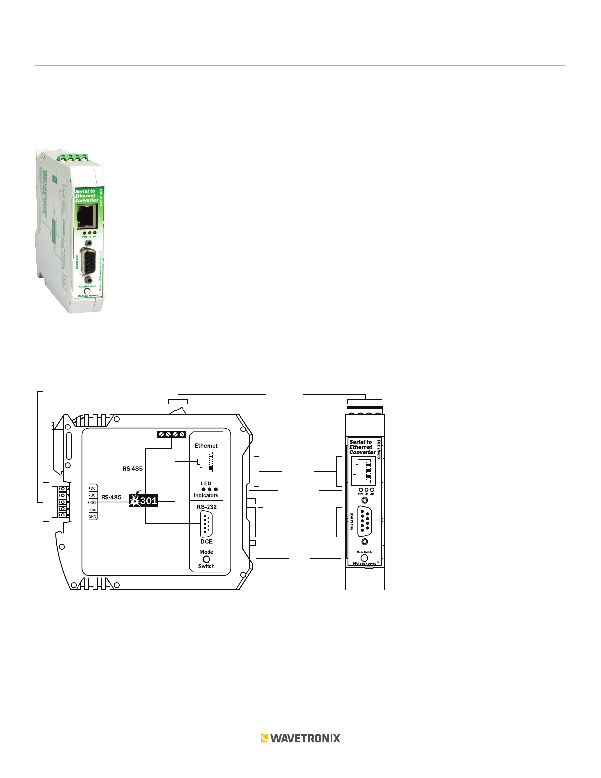
The front of the Click 301 features a DB-9 connector for RS-232 communication. A straight-through cable can be
used to connect from this port to a computer so that the device can be configured using Click Supervisor. The
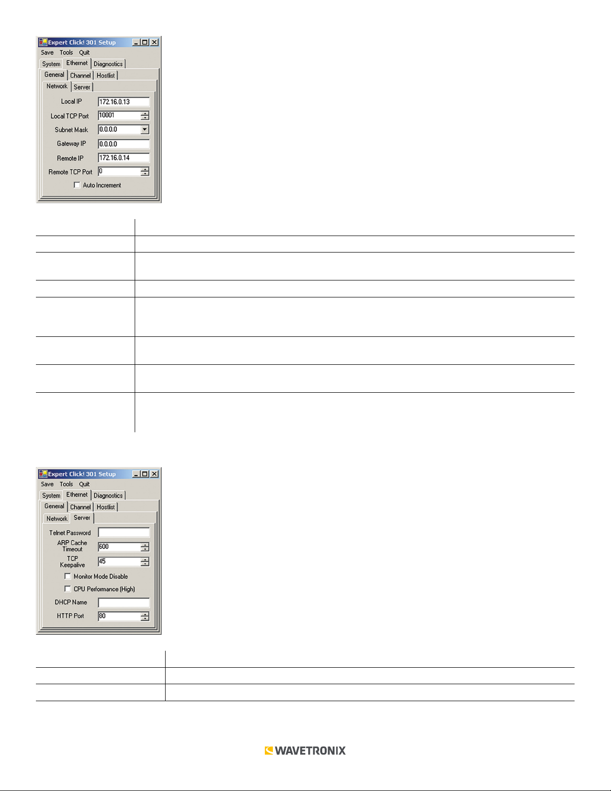
front of the device also has an RJ-45 jack for Ethernet communication.
Any data on one port will be transmitted simultaneously on all other ports.
Configuration Features
The faceplate of the Click 301 has three activity indicator LEDs:
■ PWR (red) lights up when the device has power.
■ TD (yellow) lights up when the device is transmitting data.
■ RD (green) lights up when the device is receiving data.
The LEDs are also used to indicate operation modes, which will be discussed in the On-device Configuration
section of this document.
The faceplate also has a push-button labeled Mode Switch, which is used to cycle the Click 301 through operation
modes. This will be discussed in the On-device Configuration section of this document.
On-device Configuration
The Click 301 can be configured using the push-button on the lower part of the faceplate. Press and hold the
push-button to cycle through the dierent operation modes; release the button when the desired mode is
reached. A quick press and release of the push-button will exit out of any mode and return the unit back to normal
operation. The table below and the following sections describe the dierent operating modes.
Mode LED Definition
Autobaud Green (solid) To autobaud the Click 301, press the push-button, then release when the green LED turns on.
Reset Red (flashing) To reset the Click 301 to factory defaults, press the push-button, then release when the red
LED is blinking.
Autobaud (green solid)
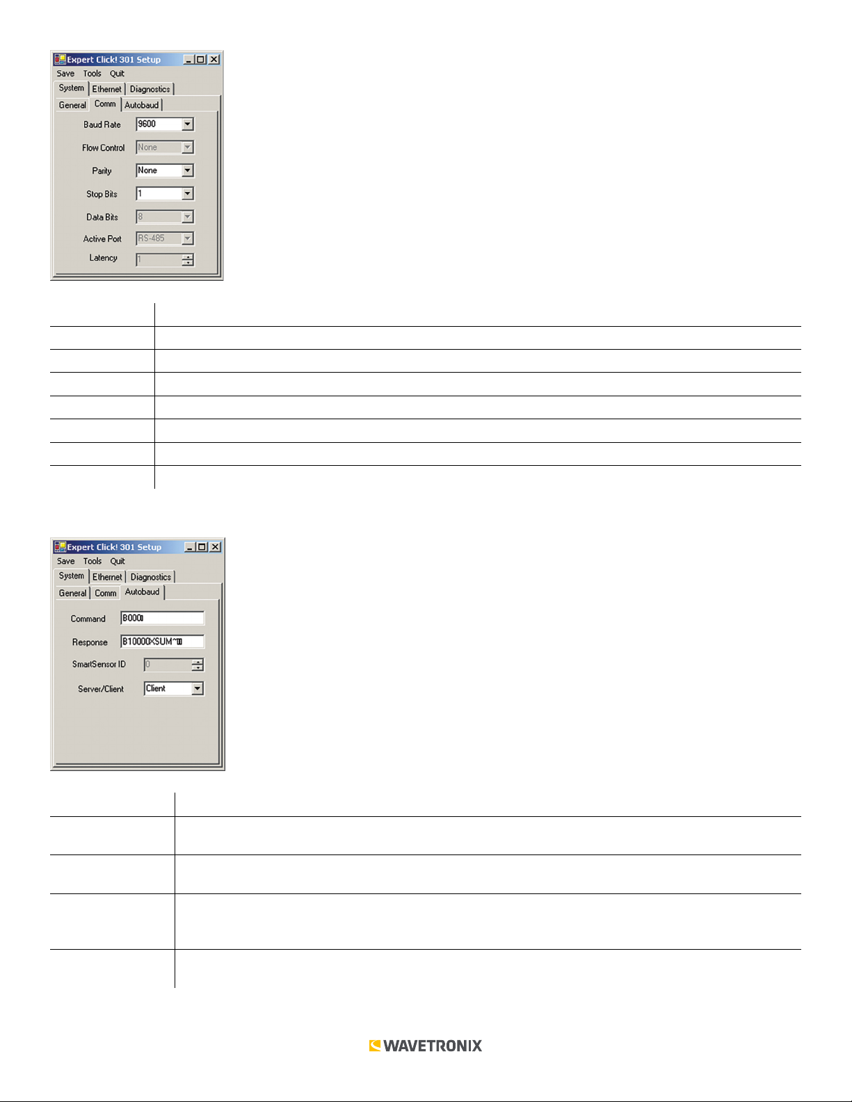
The Autobaud mode is used to match baud rates with an external device. By default, the device will attempt to
match baud rates with a SmartSensor on the bus; however, the device can be configured to autobaud with any
device that supports a serial interface.
While the device is autobauding, the green LED will be on while the red LED blinks. The autobaud was successful
if the red LED stays on and the green LED turns o. If the autobaud is not successful after a few minutes of trying,
the red and green LEDs will stay on indefinitely. In the case of a failed autobaud, push the push-button once to
return the device to its normal state.
Note. On certain devices, the yellow LED may replace the green LED in the autobaud process—that is, the yellow
LED will come on to select the autobaud process, the yellow LED is on during the autobaud process, etc.
Factory Reset (red flashing)
The Factory Reset operation will erase all user-configured fields, meaning that after the reset, the Click 301
may have to be reconfigured to work properly in its current application. If a device is not responding and

3 of 13WX-501-0531 • 01.22
not communicating, resetting the device may fix the problem. Once the device is responding, restore the
configuration needed for its current application.
To reset the Click 301 to factory defaults, release the push-button when the red LED begins flashing. The red LED
should blink slowly, then the green and yellow LEDs will flicker. When the red LED glows solid, the module has the
original factory configuration.
Computer Configuration
The Click 301 can be configured more exactly using the Click Supervisor software. See the knowledge base
article 0514 Installing and Using Click Supervisor for instructions on how to download and install Click Supervisor
and how to connect to your device using the software.
The Click 301 can be configured using one of three drivers (see the figure below).
Which driver you use will depend on what you need to use the device for. The first two drivers are known as
application drivers and are used to set the Click device to work in specific applications. Use the list below to find
the appropriate driver for your application:
■ If you intend to connect from your TOC to the Click 301 to a sensor, use the SmartSensor driver.
■ If you intend to connect from your TOC to a Click 301 to another Click 301 to the sensor, use the Point to Point driver.
To see advanced settings, use the Expert driver. This driver, which exposes every available field for the Click 301,
should only be used under the direction of Wavetronix Support.
After you have made configuration changes on a driver and saved it to the Click device, the word “current” will
appear after that driver to indicate the driver that is currently loaded onto the device.
Note. Some settings appear on multiple drivers. Changing one of those settings on any driver and saving them to
the Click device will change that setting on all other drivers it appears on.
The Backups option can be used to read configurations that have previously been saved to file.
Application Drivers
The two application drivers have very similar settings and fields; the only important dierences are found in the
Setup tab. Under the Setup tab, you can change the settings aecting the setup of the device and sensor (see the
figure and table below).

4 of 13WX-501-0531 • 01.22
The following settings are common to both application drivers.
Setting Description
Description Shows a description of the device being configured. This is only for your information and does not aect
the operation of the device.
Location Displays the location of the device being configured. This is only for your information and does not aect
the operation of the device.
Device ID Gives the ID number of the device being configured, which is used to identify the device when you are
connecting to it. By default, this number is the last five digits of the serial number, which can be found
under the About tab or on the barcode sticker on the bottom of the device. It is recommended that you
do not change this number unless another device on the network has the same ID number.
Baud Rate Allows you to change the baud rate at which the device connects to the sensor.
IP Address Lets you view and change the IP address currently assigned to the device. Each Click 301 defaults to an
IP address of 172.16.0.13.
IP Port Lets you view and change the IP port currently assigned to the device. Each Click 301 defaults to 10001.
In addition to the common settings, the Point to Point driver has the following settings:
Setting Description
Remote IP Allows you to enter the IP address of the Click 301 that you want the device you’re configuring to connect
to. Each Click 301 defaults to a remote IP address of 172.16.0.14.
Remote Port Allows you to enter the IP port of the Click 301 that you want the device you’re configuring to connect to.
Each Click 301 defaults to a remote port of 10001.
Under the About tab, you can view information about your Click 301 (see the figure and table below).

5 of 13WX-501-0531 • 01.22
The following settings are common to both application drivers:
Settings Description
Driver Names the driver you are currently working with.
Serial Number Displays the serial number of your device.
Firmware Version Shows the version of firmware your device currently has installed. If Click Supervisor detects a
discrepancy between this version and the most current version it currently has access to, you will be
prompted to upgrade when you connect to the device.
Under the Diagnostics tab, you can run diagnostics on your device (see the figure below). Click the General or
Ethernet buttons to run diagnostics on the items listed below each button. If a problem is detected, the program
will display a red square next to the item in question. If no problems are detected, a green circle will appear.
Once you have finished, use the menu bar at the top of the screen to save your settings, return to the Select
Driver screen, and more.
■ The Save menu allows you to save your settings. Select Save to File to save your settings to a file. Selecting this
will open a directory box, allowing you to name your settings file. This file will always be saved in the Wavetronix
folder created when you installed Click Supervisor, under Wavetronix > ClickHome > Drivers > 301 > User. You
can also select Save to Device to save your settings to your Click 301.
Note. If you do not save your settings to your Click 301, they will be lost the next time you power the device down.
■ The Tools menu contains five options for working with your device. Reset > System power cycles your device,
while Reset > Factory Default restores your device to the settings with which it was shipped. Restore will restore

6 of 13WX-501-0531 • 01.22
the driver to the settings currently saved on the Click 301, erasing any unsaved changes. Upgrade can be used
to manually upgrade to the most current firmware for your device. Hex View changes the view of certain settings
in the driver to hexadecimal.
■ Clicking the Quit menu exits the driver and returns you to the Click Supervisor main page.
Expert
The Expert driver allows you to see all possible settings and fields, both those available in other drivers and those
available only through this driver. The driver is divided into three tabs—System, Ethernet, and Diagnostics—which
are then subdivided further.
The System > General tab combines elements of the Setup and About tabs from the other drivers (see the figure
and table below).
Setting Description
Module Shows the last driver (besides Expert) that was loaded onto the device.
Driver Names the driver you are currently working with.
Description Shows a description of the device being configured. This is only for your information and does not
aect the operation of the device.
Location Displays the location of the device being configured. This is only for your information and does not
aect the operation of the device.
Serial Number Displays the serial number of your device.
Firmware Version Shows the version of firmware your device currently has installed. If Click Supervisor detects a
discrepancy between this version and the most current version it currently has access to, you will
be prompted to upgrade when you connect to the device.
Subnet ID Shows the subnet ID number. This option is currently not available.
Device ID Gives the ID number of the device being configured, which is used to identify the device when
you are connecting to it. By default, this number is the last five digits of the serial number, which
can be found under the About tab or on the barcode sticker on the bottom of the device. It is
recommended that you do not change this number unless another device on the network has the
same ID number.
The System > Comm tab allows you to configure how the Click device communicates (see the figure and table below).

7 of 13WX-501-0531 • 01.22
Setting Description
Baud Rate Allows you to change the baud rate at which the device connects to the sensor.
Flow Control Is used for configuring hardware handshaking. This option is currently not available.
Parity Allows you to set parity error checking.
Stop Bits Allows you to set the number of stop bits.
Data Bits Shows you the number of data bits being sent. This option cannot be changed.
Active Port Indicates on which port you are communicating with the sensor. This option cannot be changed.
Latency Indicates the latency between the sensor and the Click device. This option cannot be changed.
The System > Autobaud tab allows you to configure how the device autobauds (see the figure and table below).
Setting Description
Command Allows you to set the command sent from the device during the autobaud process. Don’t change
these values unless instructed to by Wavetronix Technical Services.
Response Shows the response the device is expecting from the above command. Don’t change these values
unless instructed to by Wavetronix Technical Services.
SmartSensor ID Shows the ID number of the sensor with which the Click device is currently communicating. This
only shows the number after you have autobauded the Click device; when the Click device is not
communicating with a sensor, this option will display a 1.
Server/Client Allows you to set whether the device is a server or client. (This option is not related to device
autobauding.)
The Ethernet > General > Network tab allows you to configure network settings (see the figure and table below).

8 of 13WX-501-0531 • 01.22
Setting Description
Local IP Lets you view and change the IP address currently assigned to the device.
Local TCP Port Lets you view and change the IP port currently assigned to the device. Each Click 301 defaults to
10001.
Subnet Mask Defines the number of bits taken from the IP address that are assigned for the host part.
Gateway IP Lets you view and change the gateway IP address. The gateway address should be the IP address
of the router connected to the same LAN segment as the unit. The gateway address must be within
the local network.
Remote IP Allows you to enter the IP address of the Click 301 that the Click 301 you’re configuring should
connect to. Each Click 301 defaults to a remote IP address of 172.16.0.14.
Remote TCP Port Allows you to enter the port of the Click 301 that the Click 301 you’re configuring should connect to.
Each Click 301 defaults to a remote port of 10001.
Auto Increment Increments the local port number for new outgoing connections automatically. The range of auto-
incremented port numbers is 50,000 to 59,999 and loops back to the beginning when the maximum
range is reached. Only use this automatic port increment feature to initiate a connection using TCP.
The Ethernet > General > Server tab allows you to configure server settings (see the figure and table below).
Setting Description
Telnet Password Allows you to enter the password required for Telnet access.
ARP Cache Timeout Defines the number of seconds (1–600) before the device refreshes the ARP cache.

9 of 13WX-501-0531 • 01.22
TCP Keepalive Defines how many seconds the unit waits during an inactive connection before checking its
status. If the unit does not receive a response, it drops that connection. The value can be
between 0 and 60 seconds. 0 disables keepalive. The default setting is 45.
Monitor Mode Disable Allows you to disable entry into the monitor mode using the ‘yyy’ or ‘xx1’ key sequence at
startup. This field prevents the unit from entering monitor mode by interpreting the stream of
characters that are received during the device server’s initialization at startup.
CPU Performance (High) Sets the device to high performance. High performance is 88 MHz, while regular is 48 MHz.
The high performance setting requires more energy.
DHCP Name Lets you enter the name of the host on the network providing the IP address.
HTTP Port Allows the configuration of the web server port number. The valid range is 1–65535. The
default port is 80.
The Ethernet > Channel > Connect tab defines how the unit makes a connection (see the figure and table below).
Setting Description
Incoming Connection Allows you to configure how the device reacts to incoming connections over the network.
Never rejects all external connection attempts.
Accept DTR accepts external connection requests only when the Modem Control In input is
asserted; this setting cannot be used with Modem mode.
Accept All is the default setting and accepts any incoming connection when a connection is not
already established.
Response Lets you set character response. When this is set to Character, a single character is transmitted
to the serial port when there is a change in connection state:
C= connected
D= disconnected
N= host unreachable
The IP address of the host connecting to the CoBos device will be provided when you use
verbose mode. This option is overridden when the Active Start Modem Mode or Active Start
Host List is in eect. The default setting is Nothing.

10 of 13WX-501-0531 • 01.22
Startup Allows you to configure active startup settings.
No Activity, the default, does not attempt to initiate a connection under any circumstance.
Any Char attempts to connect when any character is received from the serial port.
Active DTR accepts external connection requests only when the Modem Control In input is
asserted.
Specific Char attempts to connect when it receives a specific start character from the
serial port. The default start character is a carriage return. To change the character, see the
Disconnect tab.
Manual Connect attempts to connect when directed by a command string received from the
serial port.
Autostart automatically connects to the remote IP address and remote port specified when the
firmware starts.
Modem Mode causes the unit to present a modem interface to the attached serial device. It
accepts AT-style modem commands and handles the modem signals correctly.
Input Buer Allows you to choose circumstances under which the input buer will be flushed.
On Active clears the input buer when a connection is initiated from the device to the network.
On Passive clears the input buer when a connection is initiated from the network to the
device.
At Disconn. clears the input buer when the network connection with the device is
disconnected.
Output Buer Allows you to choose circumstances under which the output buer will be flushed.
On Active clears the output buer when a connection is initiated from the device to the
network.
On Passive clears the output buer when a connection is initiated from the network to the
device.
At Disconn. clears the output buer when the network connection with the device is
disconnected.
The Ethernet > Channel > Disconnect tab determines the conditions under which the unit will cause a network
connection to terminate (see the figure and table below).

11 of 13WX-501-0531 • 01.22
Setting Description
Disconnect Mode Allows you to set conditions under which the device should drop a connection.
Ignore DTR, the default, indicates that the Modem Control In doesn’t aect the
connection.
DTR Drop sets the network connection to or from the serial port to disconnect (drop)
when Modem Control In transitions from an asserted state to not asserted state.
Start Character Provides a place to enter the start character that is used to signal the active startup
function (found under the Connect tab) to attempt to connect.
Telnet Mode Enables Telnet mode.
Port Password Enables the use of a password on the serial port.
CTRL-D Disconnect Drops the connection when Ctrl-D or Hex 04 is detected. Both Telnet Com Port Cntrl and
Check EOT (Ctrl+D) must be enabled for Disconnect with EOT to function properly. Ctrl+D
is only detected going from the serial port to the network.
Hard Disconnect Closes the TCP connection even if the remote site does not acknowledge the disconnect
request.
Inactivity Timeout Sets the amount of time there can be no activity on the serial line before the device drops
the connection.
Telnet Name/Port Password Lets you enter either the Telnet name you’re using or the password for the serial port,
depending on which of those two boxes—Telnet Mode or Port Password—is checked.
The Ethernet > Channel > Packing tab allows you to configure packing settings, as well as to set other options
(see the figure and table below).
Setting Description
Packing Algorithm Enables packing, which defines how long the unit should wait before sending accumulated characters.
Idle Time (ms) Allows you to set the maximum time for inactivity.
Trailing Chars Lets you select the number of bytes to send after the end-of-sequence characters. The default is None.
Send Immediate Causes the module to send immediately after recognizing the transmit condition (sendchar or
timeout). If it is not set, any characters already in the serial buer are included in the transmission
after a “transmit” condition is found.
Send Char 2-Byte Causes the device to interpret the sendchars as a 2-byte sequence; if this option is not enabled,
the module interprets them independently.

12 of 13WX-501-0531 • 01.22
Send Characters Lets you enter up to two characters in hexadecimal. If the module receives a character on the
serial line that matches one of these characters, it sends the character immediately, along with any
awaiting characters, to the TCP connection. This action minimizes the response time for specific
protocol characters on the serial line (for example, ETX, EOT).
UDP Datagram Enables the use of UPD datagrams. This option cannot be changed here; it is enabled when you
open one of the two point to multipoint drivers and save that driver to the device.
The Ethernet > Hostlist tab allows you to set up and use a host list. When the host list is enabled, the Click 301
scrolls through the host list until it makes a successful connection to one of the addresses. After a successful
connection, the unit stops trying to connect to any others. If this connection fails, the unit continues to scroll
through the table until the next successful connection.
The host list supports a minimum of 1 and a maximum of 12 entries. Each entry contains an IP address and a
port number. The host list is flowed onto three third-level tabs. If you need to enter more than the three host
IP addresses on the first screen, go to the IP 4-9 and IP 10-12 third-level tabs. The three third-level tabs below
Ethernet > Hostlist allow you to configure the hostlist (see the figure and table below).
Setting Description
Hostlist Enable Enables the use of the host list.
Retry Counter Lets you set the number of times the module should attempt to retry connecting to the host list.
Retry Timeout Allows you to enter the duration (in seconds) the module should try to make a connection to the host
list before abandoning the attempt.
Host IP Address Lets you enter the host’s IP address.
TCP Port Allows you to set the target port number.
Under the Diagnostics tab, you can run diagnostics on your device (see the figure below). Click the General or
Ethernet buttons to run diagnostics on the items listed below each button. If a problem is detected, the program
will display a red square next to the item in question. If no problems are detected, a green circle will appear.

13 of 13
© 2022 Wavetronix LLC. All rights reserved. Protected in the US by patents viewable at www.wavetronix.com/en/legal. Protected by Canadian Patent Nos. 2461411; 2434756; 2512689; and European Patent Nos. 1435036; 1438702;
1611458. Other US and international patents pending. Wavetronix, SmartSensor, Click, Command and all associated logos are trademarks of Wavetronix LLC. All other product or brand names as they appear are trademarks or
registered trademarks of their respective holders. Product specifications are subject to change without notice. This material is provided for informational purposes only; Wavetronix assumes no liability related to its use.
WX-501-0531 • 01.22
Once you have finished, use the menu bar at the top of the screen to save your settings, return to the Select
Driver screen, and more.
■ The Save menu allows you to save your settings. Select Save to File to save your settings to a file. Selecting this
will open a directory box, allowing you to name your settings file. This file will always be saved in the Wavetronix
folder created when you installed Click Supervisor, under Wavetronix > ClickHome > Drivers > 301 > User. You
can also select Save to Device to save your settings to your Click 301.
Note. If you do not save your settings to your Click 301, they will be lost the next time you power the device down.
■ The Tools menu contains five options for working with your device. Reset > System power cycles your device,
while Reset > Factory Default restores your device to the settings with which it was shipped. Restore will restore
the driver to the settings currently saved on the Click 301, erasing any unsaved changes. Upgrade can be used
to manually upgrade to the most current firmware for your device. Hex View changes the view of certain settings
in the driver to hexadecimal.
■ Clicking the Quit menu exits the driver and returns you to the Click Supervisor main page.
Other manuals for click 301
1
Table of contents
Other Wavetronix Media Converter manuals