Wavetronix SmartSensor HD User manual

SmartSensor HD
USER GUIDE

SmartSensor HD
USER GUIDE
Provo, Utah
801.734.7200
www.wavetronix.com

WX-500-0051
10/19
© 2019 Wavetronix LLC. All Rights Reserved.
Wavetronix, SmartSensor, Click, Command, and all associated product names and logos are trademarks of Wavetronix
LLC. All other products or brand names as they appear are trademarks or registered trademarks of their respective
holders.
Protected in the US by patents viewable at www.wavetronix.com/legal. Protected by Canadian Patent Nos. 2461411;
2434756; 2512689; and European Patent Nos. 1435036; 1438702; 1611458. Other US and international patents pending.
The Company shall not be liable for any errors contained herein or for any damages arising out of or related to this docu-
ment or the information contained therein, even if the Company has been advised of the possibility of such damages.
This document is intended for informational and instructional purposes only. The Company reserves the right to make
changes in the specifications and other information contained in this document without prior notification.
FCC Part 15 Compliance: The Wavetronix SmartSensor sensors comply with Part 15 of the Federal Communications Com-
mission (FCC) rules which state that operation is subject to the following two conditions: (1) this device may not cause
harmful interference, and (2) this device must accept any interference received, including interference that may cause
undesirable operation. FCC compliance statements for applicable optional modules are to be found in the module speci-
fications. Unauthorized changes or modifications not expressly approved by the party responsible for compliance with the
FCC rules could void the user’s authority to operate this equipment.
Disclaimer: The advertised detection accuracy of the Wavetronix SmartSensor sensors is based on both external and
internal testing, as outlined in each product’s specification document. Although our sensors are very accurate by industry
standards, like all other sensor manufacturers we cannot guarantee perfection or assure that no errors will ever occur in
any particular applications of our technology. Therefore, beyond the express Limited Warranty that accompanies each
sensor sold by the company, we oer no additional representations, warranties, guarantees or remedies to our customers.
It is recommended that purchasers and integrators evaluate the accuracy of each sensor to determine the acceptable
margin of error for each application within their particular system(s).
Hereby, Wavetronix LLC, declares that the FMCW Trac Radar (SmartSensor HD, part number 101-0415) is in accordance
with the 2004/108/EC EMC Directive.
The device has been designed and manufactured to the following standards:
• IEC/EN 60950 - 1:2006, A11:2009, A1:2010, A12:2011 - Electronic equipment safety requirements.
• EN 300 440-2 - Electromagnetic compatibility and Radio spectrum Matters (ERM); Short range devices; Radio equip-
ment to be used in the 1 GHz to 40 GHz frequency range; Part 2: Harmonized EN under article 3.2 of the R&TTE
Directive.
• EN 301 489-3 - Immunity to RF interference. Compliance with transmission limitations under 1GHz and conducted
transmission over power lines, ESD.
The equipment named above has been tested by Compliance Certification Services and found to comply with the rele-
vant sections of the above referenced specifications. The unit complies with all essential requirements of the Directives.
This equipment has been evaluated at 2000m.
IP Protection: IP66
For installation into restricted access location.
All interconnecting cables shall be suitable for outdoor use.
7Introduction
1 CHOOSING A MOUNTING LOCATION
9Mounting location, height and, offset
9 Choosing where to mount
11 Choosing a mounting height and oset
13 Occlusion and multipathing
14 Fixing occlusion problems
14 Fixing multipath problems
2 INSTALLING THE SMARTSENSOR HD
15 Mounting the sensor
16 Aligning the sensor to the roadway
17 Applying silicon dielectric compound
18 Connecting the cable
3 INSTALLING POWER, SURGE PROTECTION,
AND COMMUNICATIONS
19 Installations with a pole-mount box only
20 Setting up the pole-mount box
24 Installations with a pole-mount box and traffic cabinet
24 Setting up the pole-mount box
27 Setting up the trac cabinet
4 CONNECTING TO THE SENSOR
30 Download and installation
30 Downloading SSMHD
31 Installing SSMHD
31 SSMHD main screen
32 Changing the software language
32 Changing the software size
CONTENTS

32 SSMHD communication basics
33 Making a serial connection
34 Making an Internet connection
35 Making a virtual connection
35 Troubleshooting a connection
36 Advanced communication tools
36 Viewing connection information
36 Disconnecting from a sensor
37 Using the address book
37 Viewing the error log
38 Password-protecting the sensor
39 Updating the sensor
5 CONFIGURING SENSOR SETTINGS
42 Changing General tab settings
44 Changing Ports tab settings
46 Changing Outputs tab settings
48 Changing Data tab settings
6 CONFIGURING LANES
50 Alignment
51 Checking sensor alignment
52 Lane configuration
52 Capturing lanes
53 Excluding or including a lane or area
54 Adding a lane
54 Editing a lane name
55 Deleting a lane
55 Saving the configuration
55 Sidebars, menus, and windows
56 Viewing sidebars
58 Using the Automatic Lane sidebar window
59 Using the Saved Lane sidebar window
60 Using the Vehicle Display menu
62 Using the Tools menu
64 Using the View menu
65 Using the Automatic Lane window
67 Using the Lane window
70 Using the Shoulder Area window
71 Using the Excluded Area window

7 VERIFYING LANES
74 Verification options
75 Verifying lanes using vehicle display options
75 Verifying lanes using sidebars
77 Verifying lanes using per vehicle data
78 Verifying lanes using logging
79 Lane adjustment
80 Adjusting lane properties and thresholds
8 SETTING UP AND DOWNLOADING SENSOR DATA
85 Definitions
86 Adjusting the data interval
86 Creating, adjusting and deleting speed bins
87 Creating, adjusting and deleting class bins
87 Creating, adjusting and deleting approaches
88 Using direction bins
88 Using the Speed = 0 option
88 Interval Data
89 Logging interval data
90 Storage
91 Understanding data storage tools
92 Download
93 Downloading stored detection data
95 Push
95 Enabling data push
9 USING TOOLS
100 Backing up and restoring sensor setup files
102 Viewing licensing information
103 Accessing power options
105 Index


Introduction •7
Introduction
Welcome to the Wavetronix SmartSensorTM HD user guide.
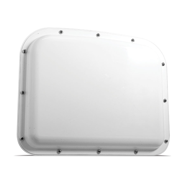
Figure 1. SmartSensor HD
This guide will cover selecting a mounting location for, installing,
and configuring a SmartSensor HD. To find the instructions for
specific tasks, see the table of contents. If your questions aren’t
answered in this guide, visit www.wavetronix.com/support for
access to supplemental materials, like technical documents and
troubleshooting information.
What you’ll need
The sensor package includes the following:
˿A SmartSensor HD

8 • SmartSensor HD User Guide
˿A mounting backplate
˿A SmartSensor HD quick start guide
The following aren’t automatically included but are necessary for
installation:
˿Sensor mount
˿SmartSensor 8-conductor cable
To support the sensor installation, you may need to order devices
for power conversion, surge protection and communication, includ-
ing some or all of the following:
˿Contact closure device (Click 100, 104, 110, or 112/114)
˿Click 200 surge protector
˿Click 201/202 AC to DC converter
˿Click 210 circuit breaker
˿Click 230 AC surge protector
˿Click 301 serial to Ethernet converter
For convenience, you can get these devices preassembled and
prewired in pole-mount boxes and cabinet backplates, available
from Wavetronix.
Service information
Don’t try to service or repair this unit; none of its components or
parts are serviceable in the field. Attempting to open this unit,
unless expressly directed by Wavetronix, will void the customer
warranty. Wavetronix is not liable for any bodily harm or damage
caused if unqualified persons attempt to service or open the back
cover of this unit. Refer all service questions to Wavetronix or an
authorized distributor.
Important note
Failure to follow the installation guidelines laid out in this guide
could result in decreased performance. If you believe it is nec-
essary to deviate from these guidelines, contact a Wavetronix
application engineer or technical support for assistance and
recommendations.

Chapter 1: Choosing a Mounting Location •9
1
Choosing a Mounting Location
Mounting location, height and, offset
Choosing where to mount
Figure 2. The HD’s radar footprint
˿The SmartSensor HD is a side-fire radar detector. It uses dual
radar beams to get highly accurate presence, speed, and
length data.
˿For best performance, make sure the lanes being detected are
all parallel to each other; avoid on- and o-ramps/turn lanes that

10 • SmartSensor HD User Guide
angle away from the road.
˿Make sure all monitored lanes are within 6 to 250 ft. (1.8 to 76.2
m) of the sensor. Up to 22 lanes can be detected.
˿If you’re putting a sensor on a road with stoplights or stop signs,
position the sensor toward middle of the block, to reduce the
likelihood of having stopped vehicles in the HD radar footprint.
Figure 3. Midblock installation
˿Keep cable lengths in mind when you pick mounting locations;
when you use the Wavetronix cable, cables can be as long as
600 ft. (182.9 m) if you’re using 24 VDC and RS-485 communi-
cations; for longer connections, consider alternate wired and
wireless options.
˿Consider timing: after a vehicle passes in front of the sensor,
there’s a slight delay before the data for that vehicle is sent
from the sensor. In a time-sensitive application, like supplying
a variable message sign with per vehicle warning messages,
make sure the sensor is far enough upstream from the sign that
the system has time to collect the data, process it, and send it
to the sign by the time the vehicles reach the problem area.
˿See if you can take advantage of any existing infrastructure in
the area. The sensor can be mounted on existing poles (with
the exception of wooden poles and trees), as long as they fall
within the acceptable oset range. You may also be able to tap
into existing cabinets, power sources, and communication net-
works. All of these options could save you time and money.

Chapter 1: Choosing a Mounting Location •11
Choosing a mounting height and offset
Mounting guidelines in feet
Offset Height (acceptable range)
6* 12 (9–19)
7* 12 (9–19)
8* 12 (9–20)
912 (9–21)
10 12 (9–22)
11 12 (9–23)
12 13 (10–24)
13 13 (11–25)
14 14 (11–28)
15 15 (12–26)
16 15 (12–27)
17 16 (13–28)
18 17 (14–29)
19 17 (14–30)
20 18 (15–30)
21 19 (15–31)
22 20 (16–31)
23 22 (16–32)
24 24 (16–33)
25 26 (17–33)
26 26 (17–34)
27 27 (18–35)
28 27 (18–35)
29 27 (18–36)
30 29 (19–37)
31 29 (19–37)
32 29 (19–38)
33 30 (19–39)
34 30 (19–39)
35 30 (20–40)
36 30 (20–41)
37 31 (20–41)
38 31 (21–42)
39 33 (21–43)
40 33 (22–43)
41 34 (22–44)
42 34 (22–44)
43 35 (22–45)
44 35 (23–46)
45 36 (23–46)
46 36 (23–47)
47 36 (24–48)
48 38 (24–48)
49 38 (24–49)
50–230 39 (25 to <offset)
Definition. Oset is
the distance between
the pole the sensor
is mounted on and
the edge of the first
lane to be detected.
Definition. Mounting
height is the distance
between the sensor
and the road’s
height, not the
bottom of the pole. If
installing a new pole,
remember that part
of the pole will likely
be below ground.
* reduction
in number
of reported
speeds.
Recommended

12 • SmartSensor HD User Guide
Mounting guidelines in meters
Offset Height (acceptable range)
2.0* 3.5 (2.5–5.5)
2.5* 3.5 (2.5–5.5)
3.0 3.5 (2.5–5.5)
3.5 3.5 (3.0–6.0)
4.0 4.0 (3.0–7.0)
4.5 4.5 (3.5–7.5)
5.0 4.5 (3.5–8.0)
5.5 5.0 (4.0–9.0)
6.0 5.5 (4.5–9.0)
6.5 6.0 (4.5–9.5)
7.0 6.5 (5.0–10.0)
7.5 8.0 (5.0–10.0)
8.0 8.0 (5.0–10.5)
8.5 8.0 (5.5–10.5)
9.0 8.5 (5.5–11.0)
9.5 8.5 (5.5–11.5)
10.0 9.0 (6.0–12.0)
10.5 9.0 (6.0–12.0)
11.0 9.0 (6.0–12.5)
11.5 9.5 (6.5–13.0)
12.0 10.0 (6.5–13.0)
12.5 10.5 (6.5–13.5)
13.0 10.5 (7.0–13.5)
13.5 11.0 (7.0–14.0)
14.0 11.0 (7.0–14.0)
14.5 11.5 (7.5–14.5)
15.0 11.5 (7.5–15.0)
15.5–70 12.0 (7.5 to <offset)
Additional information
˿If the roadway is frequently used by tall vehicles, consider
choosing a higher mounting height to help avoid occlusion.
˿Don’t use an oset of less than 6 ft. (1.8 m). Also, the sensor can
be up to 230 ft. (70.1 m) from the road, but don’t go out that far if
you can avoid it; it could lead to decreased accuracy.
˿For best results, choose the mounting height in the Height
column in the table. If you can’t, just keep it somewhere in the
acceptable range.
Note. Some
countries, such as
the UK, have their
own variant of these
mounting guidelines
due to dierences
in road layouts and
trac profiles. Please
consult with your
local Wavetronix
oce to ensure
you are installing
to the correct
local guidelines.
* reduction
in number
of reported
speeds.
Recommended
Warning. Choosing
a mounting
height outside
that range could
negatively aect
sensor accuracy.

Chapter 1: Choosing a Mounting Location •13
Occlusion and multipathing
These are two problems you might face while using a radar
detector.
Figure 4. Occlusion
Occlusion occurs when one object blocks another object from the
sensor’s view, as shown above. This can happen with
˿Tall vehicles like semi trucks
˿Signs
˿Barriers and sounding walls
˿Trees and more
Normal
detection
Signal that doesn’t
return to sensor is
scattered
Signal bouncing
o wall causes
false detection
Figure 5. Left: direct path return; right: multipath return
Multipathing occurs when a large flat surface near the sensor inter-
feres with detection. A radar signal can bounce around several
times between the surface and the vehicles before returning to the
sensor. This can make the sensor detect a vehicle where there is
none.

14 • SmartSensor HD User Guide
This can happen with
˿Buildings
˿Signs
˿Guard rails
˿Sounding walls and more
Fixing occlusion problems
˿Move the sensor higher on the pole (keeping it within the rec-
ommendations in the mounting guidelines table).
˿Move the sensor to another spot on the freeway if possible,
away from obstructions.
˿If there’s a very large barrier in the median, you could do the
following:
Use one sensor on either side of the road, pointing in (be
sure to give the two sensors a 70-ft./21.3-m lateral oset and
put them on dierent RF channels).
Put two sensors on the same pole in the middle of the
median, both pointing out (put them on dierent RF chan-
nels), but this would mean they are next to the barrier in the
median and that could cause multipath problems.
Fixing multipath problems
˿Move the sensor if possible; make sure it is separated from
overhead signs, overpasses, tunnels, parallel walls, etc. A 30-ft.
(9.1-m) lateral separation would be ideal, but even just a few feet
can make a dierence.
˿Adjust the sensor’s sensitivity thresholds in SmartSensor Man-
ager HD, as covered in chapter 7.

Chapter 2: Installing the SmartSensor HD •15
2
Installing the SmartSensor HD
Mounting the sensor
Figure 6. Mounting the sensor
1 Prepare the sensor while still on the ground: remove the large
bolts holding the end knuckle to the mount, then use the
four small bolts and lock washers to attach the knuckle to the
sensor backplate.
2 Once you're ready to mount the sensor on the pole: insert the

16 • SmartSensor HD User Guide
mounting straps through the slots on the mount.
3 Position the mount on the pole at the height you chose from the
mounting table in the previous chapter.
4 Tighten the straps.
5 Attach the knuckle you prepared earlier to the mount using the
large bolts (the cable connector should be pointed down). Don't
tighten completely yet, as you still need to align the sensor to
the roadway.
Aligning the sensor to the roadway
Figure 7. Up-and-down positioning
1 Tilt the sensor down so the front is aimed at the center of the
detection area.
Figure 8. Side-to-side positioning
2 Adjust the side-to-side angle so it’s perpendicular to the flow of
trac.
Note. Be sure to
keep the straps
adjustable, because
once you’ve used the
alignment tool in the
software, you may
need to fine-tune the
sensor’s positioning.

Chapter 2: Installing the SmartSensor HD •17
Figure 9. Rotating the sensor on a hill: incorrect (left) and correct (right)
3 If the sensor is installed on a road with an uphill/downhill grade,
rotate the sensor so that the bottom edge matches the grade
of the road (this will require the purchase of a rotating sensor
backplate).
4 Once you are satisfied with the sensor alignment and position-
ing, tighten all bolts in the mount.
Applying silicon dielectric compound
Figure 10. Applying the compound
1 Tear the tab o the tube of silicon dielectric compound that
came with the sensor.
2 Squeeze about half of the compound on the connector at the
base of the sensor.

18 • SmartSensor HD User Guide
Connecting the cable
Figure 11. Cable run through pole (left) and through conduit (right)
1 Insert the cable connector into the sensor connector. Be aware
that it is a keyed connector.
2 Twist the cable connector clockwise until you hear it click into
place.
3 Run the cable through the pole. Leave a small amount of slack
at the top; this reduces strain, allows you to create a drip loop
as shown above, and gives you something to work with should
you someday need to move the sensor to a dierent spot on
the pole.
4 If there’s excess cable, don’t cut it, as you may need it at a later
time; leave it in the pole.
Note. The HD sensor
uses an 8-conductor
cable that can
be ordered from
Wavetronix. It’s also
possible to order
a retrofit HD with a
legacy connector;
this would use the
older 9-conductor
SmartSensor cable.
Note. When you run
the cable through
the pole, don’t drill
through the sensor
mount, as the sensor
and sensor mount
may need to be
adjusted in the future.

Chapter 3: Installing Power, Surge Protection, and Communications •19
3
Installing Power, Surge
Protection, and Communications
How you install power, surge and communication modules varies
based on what enclosures you use and where they’re located.
Installations with a pole-mount box only
This is where the sensor cable runs down the pole to the pole-
mount box and to nowhere else. Power comes from solar, a battery,
or a power line that runs straight to the pole; communications are
wireless or use a comms line that runs straight to the pole.
Figure 12. Installation with pole-mount box and no cabinet
Warning. We strongly
recommend you
follow the guidelines
in this chapter,
especially as they
relate to surge
protection. Failure to
properly protect your
sensors from surges
will void the sensor
warranty. If you need
more information,
contact support@
wavetronix.com.
Other manuals for SmartSensor HD
3
This manual suits for next models
1
Table of contents
Other Wavetronix Security Sensor manuals

Wavetronix
Wavetronix smartsensor advance User manual

Wavetronix
Wavetronix SmartSensor HD Datasheet

Wavetronix
Wavetronix smartsensor advance User manual

Wavetronix
Wavetronix SmartSensor V User manual

Wavetronix
Wavetronix SmartSensor Matrix User manual

Wavetronix
Wavetronix SmartSensor Matrix User manual

Wavetronix
Wavetronix SmartSensor Matrix User manual

Wavetronix
Wavetronix SmartSensor Matrix User manual

Wavetronix
Wavetronix SmartSensor HD User manual