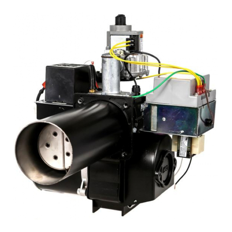
Wayne EHG User manual

1
WAYNE COMBUSTION SYSTEMS
801 GLASGOW AVE.
FORT WAYNE, IN 46803
PHONE: ( 60) 4 5-9 00
(855) WAYNECS
(800) 443-46 5
FAX: ( 60) 4 4-0904
www.waynecombustion.com
EHG
Manual 63537
-
001 | Revision
K
| Publication Date:
6
/
9
/201
4
Gas Burner
SPECIFICATIONS
De
-
rate
maximum
input f
or altitude over 2000 ft. (610 m) by 4% each 1000 ft.
( 05
m) above sea level.
Ignition
:
15.6k VAC Direct Spark Ignition.
Standard burners
are shipped with the ignition transformer mounted to the burner. If the
transformer is to be remotel mounted, the ignition wire must not exceed 36” (914.4mm) per UL795.
Supply Line Pressure Required
:
Natural or Propane 6” w.c. (1494 pa) Minimum,14”
w.c. (3487 Pa) Maximum
INSTALLATION OF BURNER
INSTALLATION OF THE BURNER MUST BE DONE BY A QUALIFIED INSTALLER IN ACCORDANCE WITH REGULATIONS OF
THE NATIONAL FUEL GAS CODE ANSI Z 3.1/NFPA 54, AND IN COMPLETE ACCORDANCE WITH ALL LOCAL CODES AND
AUTHORITIES HAVING JURISDICTION.
INCORRECT INSTALLATION, ADJUSTMENT, OR MISUSE OF THIS BURNER WILL VOID THE WARRANTY and COULD
RESULT IN DEATH, SEVERE PERSONAL INJURY, OR SUBSTANTIAL PROPERTY DAMAGE.
A QUALIFIED INSTALLER IS THE PERSON WHO IS RESPONSIBLE FOR THE INSTALLATION AND ADJUSTMENT OF THE
EQUIPMENT AND WHO IS LICENSED TO INSTALL GAS-BURNING EQUIPMENT IN ACCORDANCE WITH ALL CODES AND
ORDINANCES.
THESE INSTRUCTIONS SHOULD BE AFFIXED TO THE BURNER
OR ADJACENT TO THE HEATING APPLIANCE.
EHG
425 MBtu/hr (125 kW)
700 MBtu/hr (205 kW)
120 VAC / 60 Hz 1 Phase
24 VAC Single-Rod Gas Primar
Adjustable Flange Standard
4 inches (101.6 mm)
5 inches (127 mm) Maximum with 6 inch
(152 mm) Air Tube.
7 inches (178 mm) Maximum with 9 inch
(228 mm) Air Tube.
10 inches (254 mm) Maximum with 12 inch
(305 mm) Air Tube.
13 inches (381 mm) Maximum with 15 inch
(381 mm) Air Tube.
Burner Model:
Minimum Input:
Maximum Input:
Standard Voltage:
Flame Safety:
Mounting
Flange:
Air Tube Diameter:
Air Tube Insertions:

2
INSTALLATION LOG
BURNER MODEL:
SPECIFICATION NUMBER:
FUEL (NATURAL OR
PROPANE):
GAS ORIFICE DRILLED
SIZE:
INLET GAS PRESSURE
(in. w.c.):
CO
(%):
O
(
%):
CO (PPM):
INSTALLER’S NAME:
CONTRACTOR NAME:
CONTRACTOR
ADDRESS:
CONTRACTOR PHONE
NUMBER:
CONTRACTOR LICENSE #:
DATE OF INSTALLATION:
COMMENTS ABOUT INSTALLATION/START UP:
BURNER/APPLIANCE SERVICE LOG
SERVICE
DATE
TECHNICIAN COMPANY
/ ADDRESS
CONTRACTOR
LICENSE #
WORK PERFORMED
/ /
/ /
/ /
/ /
/
/
/ /
/ /
/ /
/ /
/ /
/ /
/ /
/ /
/ /
/ /
/ /
/ /

3
If the information in these instructions is not followed exactly, a
fire or
explosion may result causing property damage, personal injury or death.
FOR YOUR SAFTEY:
FOR YOUR SAFTEY:FOR YOUR SAFTEY:
FOR YOUR SAFTEY:
DO NOT STORE OR USE GASOLINE OR OTHER FLAMMABLE
VAPORS AND LIQUIDS IN THE VINCINITY OF THIS OR ANY OTHER APPLIANCE.
WHAT TO DO IF YOU SMELL GAS:
1. Open Windows.
. Do not try to light any appliances.
3. Do not touch electrical switches; do not use any phone in your building.
4. Extinguish any open flame.
5. Immediately call your gas supplier from a neighbor’s phone. Follow the gas supplier’s
instructions.
6. If you cannot reach your gas supplier, call the fire department.
ELECTRIC SHOCK HAZARD
HIGH VOLTAGES ARE PRESENT IN THIS
EQUIPMENT. FOLLOW THESE RULES TO AVOID
ELECTRIC SHOCK
1. Use only a properly grounded circuit. A ground
fault interrupter is recommended.
. Do not spray water directly on burner.
3. Turn off power before servicing.
4. Read the owner’s manual before using.
OVERHEATING HAZARD
SHOULD OVERHEATING OCCUR:
1. Shut off the manual gas valve to the appliance.
. Do not shut off the control switch to the blower.
CARBON MONOXIDE
POISONING HAZARD
CARBON MONOXIDE IS A COLORLESS, ODORLESS GAS THAT CAN KILL. FOLLOW
THESE RULES TO CONTROL CARBON MONOXIDE.
1. Do not use this burner if in an unvented, enclosed area. arbon monoxide may
accumulate.
. Do not misadjust the pressure regulator. High pressures produce carbon monoxide.
3. heck flue gases for carbon monoxide. This check requires specialized equipment.
4. Allow only qualified burner service persons to adjust the burner. Special instruments and
training are required.
5. Read the owner’s manual before using.

4
CONTENTS
PAGE
SECTION I INSTALLATION.
A. GENERAL..
B. VENTILATION...
. MOUNTING TO EQUIPMENT.....
D. GAS PIPING......
E. ELE TRI AL SUPPLY..
F. BURNER ORIFI E SIZING AND INSTALLATION..
G. 120VA SOLENOID SHUT-OFF GAS VALVE
H. PRESSURE REGULATOR ADJUSTMENT.
I. GAS PRESSURE SWIT HES
SECTION II INITIAL START UP..
SECTION III OPERATION AND TROUBLESHOOTING....
SECTION IV SERVICE..
TECHNICAL INFORMATION...
CONSUMER INSTRUCTIONS
WARRANTY...
5
5
5
5
5
7
7
10
10
11
1
15
6
34
45
46

5
SECTION I
INSTALLATION
A.
GENERAL
Installation of these power gas burners must conform
to local codes, or in their absence, the National Fuel
Gas ode, ANSI Z223.1/NFPA 54.
In ANADA, “The equipment shall be installed in
accordance with the Provincial Installation
Requirements, or in their absence, the GA B149.1
and B149.2 Installation odes shall prevail.”
Authorities having jurisdiction should be consulted
before installations are made.
NOTICE: ANSI or local installation code compliance
is the sole responsibility of the qualified installer.
B. VENTILATION
The EHG burner models covered by this manual shall
not be installed in an appliance located where normal
air circulation or infiltration is limited in providing all
the air necessary for proper combustion and draft
hood dilution air.
When the heating appliance is installed in a
tightly closed room without ventilation openings
to outdoors, or other rooms, provisions shall be
made for supplying air for combustion through
special openings, one near the floor line and the
other near the ceiling. Each is to be sized on the
basis of one square inch (645. mm ) or more of
free area for each 1,000 Btu/hr (0. 9 kW) input.
D.
GAS PIPING
NOTICE: All piping must comply with state and/or
local codes. The available gas supply pressure
should be within minimum and maximum pressures
shown in the burner specifications. If the gas supply
pressure exceeds the 14” w.c. (3.5 kPa) maximum,
an intermediate main gas regulator must be installed
ahead of the main gas manual shutoff valve shown in
Figure 2.
WARNING: Failure to install the intermediate gas
regulator could result in gas leakage from gas
valve(s) ad/or the burner’s automatic pressure
regulator.
A drip leg or sediment trap must be installed in the
supply line to the burner. A pipe union shall be
installed in the gas line adjacent to, and upstream
from the main gas manual shutoff valve. See Figure
2.
The gas supply piping to the burner should branch off
from the main gas supply line as close to the gas
meter as possible. Do not connect to the bottom of a
horizontal section. For pipe sizing and lengths refer to
the tables on pages 44 and 45.
Use new black iron pipe and malleable fittings free
from burrs and defects. Use pipe joint compound
resistant to liquefied petroleum gases.
A 1/8” NPT plugged tapping accessible for test gauge
connection shall be provided immediately upstream of
the gas supply pressure connection for determining
gas supply pressure to the burner. Test new supply
piping for leaks. CAUTION: DURING PRESSURE
TEST FOR LEAKS IN SUPPLY PIPING, THE
BURNER MUST BE DISCONNECTED TO
PREVENT EXPOSING THE COMBUSTION
REGULATOR/GAS VALVE(S) TO PRESSURES
GREATER THAN 1/ ” PSIG (3447 PaG) POSSIBLY
DAMAGING
THE
SE CONTROLS
AND VOIDING
C.
MOUNTING TO EQUIPMENT
THE BURNER AIR TUBE MUST NOT BE
ALLOWED TO EXTEND INTO THE CHAMBER
PROPER; IT MUST BE SET 1/8 INCH (3. MM)
SHORT OF THE INSIDE SURFACE.
Before permanently securing the burner to the
heating appliance with the mounting flange or
cementing around the air tube in the combustion
chamber opening, check that the burner head
assembly is free of foreign materials and that the
sensor and electrode probes have not been damaged
or repositioned, see Figure 1.

6
ELECTRODE SETTINGS
Supply Line onnection to Burner
Figure
Drip Leg
3’’ MIN
(76.2 mm)
ontrol Manifold
Union
Tee
Direction
of Flow
Pipe ap
Manual Shutoff
Valve
1/8” (3.2mm) N.P.T.
Plugged Tapping
Pressure Gage Port
Figure 1
0.125” (3.2mm)
0.105” (2.7mm)
0.75”
(19.1mm)
0.8” (20.3mm) REF
PROBE DIM “A” REF
IGNITER 1.06 (26.9mm)
SENSOR
0.84 (21.3mm)

7
EHG Orifice Size Chart (LP)
Btu/hr
Input
LP Gas
Orifice Part No. Manifold
Pressure in. w.c.
Drill
Decimal
425,000 (125 kW) “U” 0.3680” (9.35mm) 62438-031M 3.7 (922 Pa)
450,000 (132 kW) 3/8” 0.3750” (9.53mm) 62438-036M 3.5 (872 Pa)
500,000 (147 kW) 27/64” 0.4219” (10.72mm) 62438-037M 3.5 (872 Pa)
550,000 (161 kW) 29/64” 0.4531” (11.51mm) 62438-038M 3.5 (872 Pa)
600,000 (176 kW) 31/64” 0.4844” (12.3mm) 62438-039M 3.5 (872 Pa)
650,000 (191 kW) 1/2” 0.5000” (12.7mm) 62438-040M 3.5 (872 Pa)
700,000 (205 kW) 37/64” 0.5781” (14.68mm) 62438-041M 3.5 (872 Pa)
EHG Orifice Size Chart (Natural)
Btu/hr
Input
Natural
Gas
Orifice Part No. Manifold
Pressure in. w.c.
Drill
Decimal
425,000 (124.6 kW) 15/32” 0.4688” (11.91mm) 62438-011M 3.8 (922 Pa)
450,000 (131.9 kW) 31/64” 0.4844” (12.3mm) 62438-039M 3.5 (872 Pa)
500,000 (146.5 kW) 33/64” 05156” (13.1mm) 62438-043M 3.5 (872 Pa)
550,000 (161.2 kW) 35/64” 0.5469” (3.89mm) 62438-044M 3.5 (872 Pa)
600,000 (175.8 kW) 19/32” 0.5938” (15.08mm) 62438-045M 3.5 (872 Pa)
650,000 (190.5 kW) 5/8” 0.6250” (15.88mm) 62438-046M 3.5 (872 Pa)
700,000 (205.2 kW) 23/32” 0.7188” (18.26mm) No orifice 3.5 (872 Pa)
F.
BURNER ORIFICE SIZING
AND
INSTALLATION
The EHG power gas conversion burners are
approved for use with natural and propane gas only.
The EHG burner models are shipped labeled and
orificed for natural gas. To convert to propane gas
and/or increase Btu/hr input on natural or propane
gas, an orifice kit is supplied with each burner with the
orifices shown in Figure 3.
To remove or interchange main orifice discs refer to
Figure 27.
1. Remove 1” NPT orifice plug, item #5.
2. Remove orifice spring, item #4, to access and
remove orifice disc, item #3.
3. Install desired orifice from Figure 3, making sure it
is seated flat in the orifice holder, item #2.
4. Replace orifice spring and securely tighten 1”NPT
orifice plug (using proper pipe dope) into orifice
holder.
E.
ELECTRICAL
SUPPLY
The installation must be wired and grounded in
accordance with local codes or in their absence, with
the National Electric ode ANSI/NFPA No. 70 latest
edition. In anada, all wiring shall be done in
accordance with the anadian Electrical ode.
For the 120 VA wiring to the burner, use solid
copper conductor wire no lighter than #14 AWG. If a
fused disconnect is used, it should be fused for a
minimum of 15 amps.
CAUTION: The burner is equipped with its own 24
VA transformer. Do not add any 24 VA power
consuming device in the 24 VA control circuit of the
burner, as it could overload the transformer.
CAUTION: Label all wires prior to disconnection
when servicing controls. Wiring errors can cause
improper and dangerous operation.
Verify proper operation after servicing.
NOTE: if any of the original burner wiring must be
replaced, it must be replaced with #18 AWG 105
wire or equivalent.
See Section III – Operation and Troubleshooting for
applicable burner wiring diagrams.
Figure 3

8
Gas Pipetrain:
The pipetrain includes High & Low Gas Pressure Safety Switches, two manual ball valves, two 120 VA Solenoid Shut-off
Valves, a Main Gas Pressure Regulator, and gas test ports per the requirements of UL795. Upon request the pipetrain
can be supplied without a Gas Pressure Regulator, but the correct Gas Pressure Regulator must be installed before
operation. The pipetrain components may be shipped separate, and minor field plumbing and wiring are required.
Additional pipetrains that comply with SD-1, NFPA, FM or GAP (formerly IRI) are available. Upon request, the pipetrain
can be pre-assembled and pre-wired.
Gas Train Connection:
In most cases, the burner is supplied with a pre-assembled gas train. If this is the case, attach the gas train to the gas
inlet connection of the burner (figure 4) making sure the gas train is orientated properly. The solenoid shut off valves and
pressure regulator have arrows on the housings that indicate the direction of gas flow. When making connections that
utilize NPT threads, use pipe joint compound that is resistant to the effects of liquefied petroleum gases. Turn the manual
valves in the gas train to the off position. Using new black iron pipe and malleable fittings, connect the gas supply piping
to the inlet of the gas train (figure 4). Refer to Section I.D, GAS SUPPLY PIPING.
NOTE: When connecting the gas train to the burner, the length of piping between the ball valve closest to the burner and
the gas inlet on the burner, must not exceed 20”. If installation of the burner and gas train to the equipment requires
lengthening the gas train, the length of pipe (including the ball valve) must not exceed 25” in total.
Figure 4
If the gas train is not pre-assembled, use new black iron pipe, malleable fittings, and suitable pipe joint compound to
assemble the gas train. Examples of assembled gas trains are shown in Figures 31 and 32 (pages 41-44). The manual
valves, solenoid valves, pressure switches and pressure regulator must be connected as described in the installation
instructions for the given component, and in the flow sequence as shown in Figures 31 or 32. The solenoid shut off valves
and pressure regulator have arrows on the housings that indicate the direction of gas flow. When assembling these
components into the gas train, make sure the arrows point in the direction of gas flow. Following the assembly of the gas
train, attach it to the burner and gas supply piping as described above.
Note: The gas train, and all its safety components, should be leak tested after installation. 1/8″ NPT fittings have been
provided to isolate and test the solenoid valves. The train, and all safety components, should be tested for leaks and
functionality at regular intervals.
Note: Gas trains are heavy causing stress to the gas connections on the burner. The gas train must be properly
supported to minimize the potential for stress on the burner’s gas piping connections.
Electrical Connections:
The installation must be wired and GROUNDED in accordance with local codes or in their absence, with the National
Electric ode ANSI/NFPA No. 70-2002 or latest edition.
In ANADA, all wiring shall be done in accordance with the anadian Electrical ode.
Gas Inlet
Pressure Tap

9
There are two sets of wires extending out of the control panel. The black and white wires marked “L1” and “L2” should be
connected to the 120 VA supply line. The black and white wires marked “GV1” and “GV2” are to be connected to the
gas train. The green wire exiting the gas train must be connected to the ground lug in the control panel.
For the 120 VA wiring to the burner, use solid copper conductor wire not lighter than #14 AWG. If a fused disconnect is
used, it should be fused for a minimum of 15 amps.
For the 120 VA wiring from the burner to the gas train, use solid copper conductor wire not lighter than #14 AWG.
CAUTION: The burner is equipped with it’s own 24 VA transformer. Do not add any 24 VA power consuming device in
the 24 VA control circuit of the burner, as it could overload the transformer.
CAUTION: Label all wires prior to disconnection when servicing controls. Wiring errors can cause improper and
dangerous operation. Verify proper operation after servicing.
NOTE: If any of the original burner wiring must be replaced, it must be replaced with #18 AWG 105 degrees wire or
equivalent. See Section 3- Operation and Troubleshooting for applicable burner wiring diagrams.

10
G. 1 0VAC SOLENOID SHUT-OFF GAS VALVES
The gas solenoid shut-off valves may be pre-plumbed onto the pipetrain. The pipetrain may also be pre-wired for
convenience, but the electrical wiring from the burner must be connected in the field.
Figure 5
Figure 6
Figures 5 and 6 show one type of solenoid valve that is used in the gas trains. When installing solenoid valves into a gas
train, the valves must be connected in the proper orientation. The arrow on the valve body depicts the direction of gas
flow. Do not install the valves in a backward orientation.
Refer to the wiring diagram in Figure 11 of this manual for proper wiring of solenoid valves.
H. PRESSURE REGULATOR ADJUSTMENT
The gas pressure regulator is NOT factory preset, and must be field-adjusted while the burner is in operation. Refer to
Figure 3 for pressure requirements.
When adjusting the regulator outlet pressure to set input capacity per the tables in Figure 3, remove the regulator cap for
access to the slotted adjustment screw. Turning the screw counter clockwise reduces manifold pressure, clockwise
increases the pressure.
NOTE: MANIFOLD PRESSURE ADJUSTMENTS CAN ONLY BE MADE WITH THE BURNER RUNNING AND THE
GAS ON.

11
The 1/8″ NPT pressure tap for manifold pressure measurement is located on the side of the burner’s manifold pipe (see
figure 4). Use a “u”-tube manometer or dial type pressure gauge, scaled from 0″w.c. to 15.0″ w.c. (3736.5Pa) to read
pressure.
Figure 7
I. GAS PRESSURE SWITCHES
MOUNTING
All switches can be mounted in either horizontal or vertical position. Switches should be reasonably level but do not
require accurate leveling.
Switches have been factory calibrated and tested for leaks. However, it is recommended that the switch body, gas pipe
inlets and connections be soap bubble tested for leaks after installation.
OPERATION
Low Gas Pressure Models
Low gas pressure switches break the electrical circuit on pressure drop at the point when gas pressure becomes lower
than the indicated set pressure.
Before the manual reset button can be properly latched, gas pressure in the chamber must be higher than the indicated
setting.
High Gas Pressure Models
High gas pressure switches break the electrical circuit when pressure rises above the indicated preset pressure.
Range Adjustment - All Models
To adjust gas pressure cut-off setting, remove the cover. Turn the range scale adjustable knob to increase pressure
setting or decrease pressure setting. Install cover and tighten the cover screws to prevent tampering. Proper adjustment
of the high and low gas pressure switches is explained in section II.
Regulator ap

12
SECTION II
INITIAL START UP
NOTE: Read the applicable sequence of burner/primary gas control operation, gas pressure switches, etc. in Section III
Operation and Troubleshooting before proceeding.
1. Lay out combustion test equipment, manometers, stopwatch, D micro-amp meter, and other miscellaneous tools as
needed.
. Adjust the primary air shutter setting per the dimensions shown in the chart below. See figures 22 -26 (pages 31-32)
for air band adjustment instructions.
NOTE: Remove block-out plate using a 1/2" nut driver or wrench from the side of the burner IF the firing rate is
over 650,000(191 kW) Btu/hr on LP ONLY. See chart below. For location of block-out plate see figure 9 below.
EHG Start-Up Reference Chart
LP Gas Natural Gas
Btu/hr
Input
Air shutter
Manifold
Pressure Air shutter
Manifold
Pressure
Opening Block-out
Plate Inches w.c.
Opening Block-out
Plate Inches w.c.
425,000 (125 kW) 3/8” (10mm) yes 3.7 (922Pa)
5/16” (8mm) yes 3.8 (947Pa)
450,000 (132 kW) 1/2” (13mm) yes 3.5 (872Pa)
1/2” (13mm) yes 3.5 (872Pa)
500,000 (147 kW) 13/16” (21mm) yes 3.5 (872Pa)
13/16” (21mm)
yes 3.5 (872Pa)
550,000 (161 kW) 1-1/8” (29mm) yes 3.5 (872Pa)
1” (25mm) yes 3.5 (872Pa)
600,000 (176 kW) 1-3/8” (35mm) yes 3.5 (872Pa)
1-1/2” (38mm) yes 3.5 (872Pa)
650,000 (191 kW) 1-3/4” (19mm) removed 3.5 (872Pa)
1-3/4” (44mm) yes 3.5 (872Pa)
700,000 (205 kW) 1-7/8” (48mm) removed 3.5 (872Pa)
2-1/8” (54mm) yes 3.5 (872Pa)
Note: Air Shutter Opening Dimensions and Gas Manifold Pressures are approximate
and must be properly adjusted with calibrated emissions equipment.
Figure 8
Block out plate location
Figure 9
Block out
Plate

13
NOTE: Initial activation of the burner should begin with checking the function of the automatic controls by means of a “dry
run” before gas is supplied to the main burner nozzle – through a complete main burner firing cycle and a complete check
of all automatic safety controls with the test firing valve in the closed position then through an activated firing cycle.
3. Temporarily remove the covers from the High and Low gas pressure switches and set the switches using the dials. The
high gas pressure switch should be set at the highest pressure setting, as an initial starting point. The low gas pressure
switch should be set at the lowest pressure setting, as a starting point. NOTE: These settings must be re-adjusted after
the burner is ignited.
4. Open the ball valve to the inlet of the gas pipetrain. Make sure the ball valve nearest the burner (the outlet of the gas
pipetrain) remains closed. Test all new piping for leaks with a soapy solution or leak detector. Do not use an open flame
to test for gas leaks. Push the manual reset buttons on the gas pressure switches.
5. Turn on the main electrical power and set the thermostat or operation control to call for heat. Turn the burner on-off
switch to the “on” position. Allow the combustion fan to run a MINIMUM of 5 minutes to purge the combustion chamber
and appliance heat exchanger. The amber indicator light shows that the burner is powered and the switch is in the “on”
position.
6. Turn the burner on-off switch to the “off” position or set the thermostat or operating control below room temperature,
shutting the burner “OFF” at least 1 minute to RESET the primary control.
7. Open the ball valve on the outlet of the pipetrain (nearest the burner).
8. Power the burner, turn the burner on-off switch to the “on” position and set the thermostat or operating control to call for
heat. The burner will start and go through the applicable sequence of burner/primary gas control operation, refer to
Section III for sequence of operation.
NOTE: On new gas line installations, air may be trapped in the gas line, the burner may experience several lockouts until
all the air is purged from the lines.
9. Once the burner is running, adjust the gas pressure regulator as described in Section I, paragraph H – Pressure
Regulator Adjustment, based on the pressure described in Figure 8.
10. A more accurate Btu/hr (kW) input can be determined by using the gas service meter with the burner operating (all
other gas appliances must be off). The hand on the gas meter dial with the lowest cubic feet value (fastest revolving dial),
should be clocked (timed) for one complete revolution. Use the following formula:
3600 x cubic ft. per revolution x Btu value/cubic ft = Btu/hr
seconds per revolution
Natural Gas Example: Timing one revolution of the 1ft3 dial at 6 seconds on natural gas (roughly 1000 Btu/ ft3
heating value).
3600 x 1 x 1000 = 600,000 Btu/hr
6
Propane Gas Example: Timing one revolution of the 1ft3 dial at 15 seconds on propane gas (roughly 2515 Btu/
ft3 heating value).
3600 x 1 x 2515 = 603,600 Btu/hr
15
11. After the desired input has been obtained, re-adjust the primary air damper open or closed to visually obtain a blue
flame with well-defined orange or yellow tips for natural gas, or well defined yellow tips for propane gas. If the burner is
firing into a refractory lined chamber, a blue flame may not be possible to obtain.
1 . After the burner has been in operation for at least 10 minutes, assuring combustion chamber and heat exchanger are
fully warmed, take combustion analysis flue gas samples just ahead of the draft control in the flue pipe. A combustion
gas analyzer should be used to fine-tune the burner.
NOTE: ALWAYS USE RELIABLE COMBUSTION TEST INSTRUMENTS. BEING PROFICIENT IN THE USE OF
THESE INSTRUMENTS AND INTERPRETING THEIR DATA IS NECESSARY FOR SAFE, RELIABLE AND EFFICIENT
BURNER OPERATION.

14
13. Perform the following combustion analysis. All adjustments below must be made with the following instruments: draft
gauge, O2 or O2 analyzer and O tester.
A. Adjust the primary air damper to provide about 25% excess combustion air. onfirm this by checking the flue gas
for its FREE OXYGEN (O2) or ARBON DIOXIDE ( O2) PER ENTAGES with a test instrument. Free oxygen
should be about 4.5%, or carbon dioxide should be about 9.5% for natural gas, 12.1% for propane gas.
B. ARBON MONOXIDE ( O)– Should be checked for its presence in the flue gas. This percentage
should not exceed .04% (or 400 PPM air free).
If an O2 analyzer is used:
OAIRFREE = x OPPM
If a O2 analyzer is used:
For Natural Gas: OAIRFREE = x OPPM
For Propane Gas: OAIRFREE = x OPPM
. NOTE: The EHG was designed to fire into slightly positive, balanced, or slightly negative combustion chambers. For
optimal performance, check overfire draft and adjust to NEGATIVE -.01 (-2.5Pa) to -.02 (-5.0 Pa) inches w.c. during
burner operation.
D. The flue gas temperature should be between 325°F (163 ° ) and 550°F (288 ° ) for gas burners. Higher flue gas
temperatures indicate overfiring or excessive draft through the appliance. Lower flue gas temperatures may cause
excessive condensation and indicate underfiring. onsult your local utility or the appliance manufacturer for acceptable
flue gas temperatures.
CAUTION: IF THE BURNER Btu/hr (kW) INPUT IS HANGED, THE AIR SHUTTER MUST BE ADJUSTED. REPEAT
STEP 13
14. Adjust the High & Low gas pressure switches according to actual firing conditions. The High gas pressure switch
should be set at approximately 4”w.c. and the Low gas pressure switch should be set at approximately 2”w.c. for close
burner control. Nuisance lockouts will occur if the switch settings are too close to the gas manifold setting, and
fluctuations in gas pressures occur. Reattach switch covers.
15. Record the installation data, the combustion readings, etc., and affix to this manual, or the burner and/or appliance.
Space has been provided at the back of this manual for start-up notes, dealer’s name, address, telephone number, as
well as the date of installation.
SUGGESTION: All new installations should be re-inspected for proper combustion and burner operation after one or two
weeks of normal operation.
For subsequent normal starting and shut off procedure, refer to the “ onsumer Instructions” in the back of this manual or
the instruction plate attached to the burner.
TO RESTART THE BURNER AFTER A FLAME FAILURE, remove power from the burner for 1 minute to reset the
primary controller. Push the manual reset on the Low Gas pressure switch. The burner should relight after power is
restored and the unit has a call for heat. If problems persist, refer to the troubleshooting section of this manual.
To stop the burner in the event of an emergency, remove power from the main electrical disconnect, shut off any manual
gas ball valve, or turn the burner on-off switch to the off position.
20.9
(20.9 – %O2)
11.7
% O2
13.8
% O2

15
SECTION III
OPERATION AND TROUBLESHOOTING
SEQUEN E OF OPERATION – EHG POWER GAS BURNER UTILIZING HONEYWELL S89F GAS
PRIMARY W/BUILT IN 30 SE OND PREPURGE
On a call for heat, voltage (24VA ) is applied to the motor start relay and air switch. Once the fan motor
reaches operating rpm, the available combustion air will close the air-proving switch contacts, energizing the
gas primary control.
The S89F gas primary control has an internal 30-second pre-purge timer. After the initial 30 second pre-purge,
an internal 8-second safe start check of the S89F will commence. Once this is successfully completed, the
S89F simultaneously energizes the gas valves and ignition transformer. Gas flows and the transformer
produces an approximate 15,000 volt spark end point grounded at the burner head establishing main burner
flame.
At the start of each heat cycle, there is a trial for ignition period of four (4) seconds duration. Normally, burner
flame will be established before the end of this period. Once the flame is established, sparking will cease and
the flame rod will provide flame monitoring to the S89F gas control primary for the remainder of the heat cycle.
If the flame should be extinguished during the heat cycle, the S89F gas control primary will go into the 30
second pre-purge and 8 second safe start check, then re-energize the gas valve and ignition transformer in an
attempt to establish the main burner flame. If this does not occur within the 4-second trial for ignition period,
the S89F gas primary control will go into lockout de-energizing the gas valves and ignition transformer.
To restart the system, the main power or thermostat must be de-energized momentarily, then re-energized. If
at any time during the heat cycle, there is a failure of the combustion air supply to the burner, the air switch will
open, putting the system into lockout, closing the gas valves.
EHG POWER GAS BURNER
WITH HONEYWELL S89F GAS PRIMARY
AND GAS VALVE/REGULATOR COMBINATION
Figure 10

16
EHG POWER GAS BURNER
WITH HONEYWELL S89F GAS PRIMARY
AND GAS TRAIN ASSEMBLY
Figure 11

17
EHG POWER GAS BURNER
WITH HONEYWELL S89F GAS PRIMARY
AND GAS TRAIN ASSEMBLY (CONTINUED)
Figure 11 (continued)

18
FLAME SENSING
The Honeywell S89 series primary ignition controls utilize the flame current rectification principal for main
burner flame sensing.
The flame rectification phenomenon occurs as follows: The ignited gas flame causes the immediate
atmosphere around the flame to become ionized (gas atoms become electrically charged). The ionization
causes the atmosphere around the flame to become electrically conductive. An A voltage output from the
control sensing circuit is routed through the flame sensor probe. When the sensor probe and the burner head
are both in contact with a properly adjusted flame, the burner head with its larger surface attracts more free
electrons, thus becoming negatively charged. The sensor probe with its small surface area gives up free
electrons, thus becoming positively charged. The free electrons from the A voltage in the sensor probe flow
through the ionized gas flame to the grounded burner head. As the A current passes through the gas flame, it
is rectified into a D current flowing back to the grounded side of the sensing circuit. The flame in actuality is a
switch. When the flame is present, the switch is closed allowing current to flow through the sensing circuit of
the control. When no flame is present, the switch is open with no current flowing through the sensing circuit of
the control.
The D current flow is measured in units called D microamperes. A steady D microampere current of 0.8
minimum (and steady) or higher through the sensing circuit of the primary ignition control is sufficient to keep
the burner running without a safety lockout. See Figure 1 for sensor probe and electrode dimensional settings,
Figure 12 for flame current measurement.
Honeywell S89F Flame Signal Measurement
Figure 1

19
EHG SERIES WITH A HONEYWELL S89F PRIMARY IGNITION CONTROL
TROUBLESHOOTING GUIDE
MOTOR DOES NOT START
1. CHECK VOLTAGE INPUT TO BURNER, 120 VAC DIAGNOSE REASON FOR ABSENSE OF
VOLTAGE
2. CHECK FOR VOLTAGE AFTER BURNER “ON” SWITCH REPLACE SWITCH
3. CHECK FOR CONTINUITY THROUGH 24 VOLT T
STAT IF USED, OR IF BURNER
IS CYCLED ON OFF THROUGH 120V CIRCUIT, T T TERMINALS MUST BE
JUMPERED
REPAIR T
STAT OR ADD JUMPER AS
NECESSARY
4. CHECK LOW VOLTAGE TRANSFORMER FOR 24 VOLT OUTPUT. 24 VAC
SHOULD BE PRESENT ACROSS TERMINALS 1 AND 3 OF THE MOTOR START
RELAY
5. CHECK FOR 120VAC BETWEEN TERMINAL 4 ON MOTOR START RELAY AND L2
CHECK ELECTRICAL WIRING AND CONNECTIONS,
REPLACE 24VAC 30VA TRANSFORMER IF NECESSARY
6. REPLACE MOTOR.
OK
OK
OK
OK
OK
NO
NO
NO
NO
6. CHECK ELECTRICAL WIRING AND CONNECTIONS
CHECK ELECTRICAL WIRING AND CONNECTIONS,
REPLACE MOTOR START RELAY IF NECESSARY
NO
OK
6. DOES MOTOR SHAFT TURN FREELY?
OK
1.
CHECK BLOWER CLEAERANCE
2. LUBRICATE MOTOR BEARINGS
NO

20
OK
OK
OK
IGNITION ARC ESTABLISHED – NO FLAME
1. RESET CONTROL
MOTOR STARTS
COMPLETES 30 SECOND PREPURGE CYCLE, 8 SECOND SAFE START CHECK AND TRIAL FOR
IGNITION, 4 SECONDS HONEYWELL SERIES
S89F.
NOTE:THE BURNER MOTOR WILL CONTINUE TO OPERATE DURING THE LOCK OUT MODE WHEN THE THERMOSTAT CIRCUIT IS CALLING FOR BURNER OPERATION.
2. CHECK FOR CORRECT GAS PRESSURE AT MANIFOLD. IF NECESSARY, ADJUST PER FIGURE 3. IF
NO GAS PRESSURE CONTINUE BELOW.
IN ORDER FOR THE FOLLOWING FUNCTIONAL TEST TO BE MAD
E, THE CONTROL MUST BE RESET AND THE TESTS MONITORED DURING THE 4 SECOND TRIAL FOR IGNITION
PERIOD THAT OCCURS AT THE END OF THE 30 SECOND PREPURGE AND 8 SECOND SAFE START CHECK CYCLE.
4
. CHECK FOR 24
VAC AT GAS VALVE
RELAY
TERMINALS 1 AND
3.
NOTE: VOLTAGE WILL ONLY BE PRESENT DURING IGNITION
TRIAL.
OK
OK
CHECK ELECTRICAL W
IRING AND CONNECTIONS. BE
SURE LEADS ARE ON CORRECT GAS VALVE
TERMINALS. VERIFY TRANSFORMER VOLTAGE OUTPUT
OF 24VAC
REPLACE PRIMARY
IGNITION CONTROL.
5. CHECK FOR 120 VOLTS BETWEEN TERMINAL 2 ON GAS VALVE
RELAY AND L2.
6. CHECK FOR 120 VOLTS BETWEEN TERMINAL 4 ON GAS VALVE
RELAY AND L2. VOLTAGE IS ONLY PRESENT DURING TRIAL FOR
IGNITION.
OK
NO
OK
ADJUST AIR SHUTTER
PER FIGURE 8. AFTER THE BURNER
FIRES, SET UP THE BURNER PER SECTION II.
3. CHECK FOR 120
V
OLTS ACROSS WIRES FEEDING
GAS
TRAIN.
NOTE: VOLTAGE WILL ONLY BE PRESENT DURING
IGNITION TRIAL. IF NO VOLTAGE CONTINUE BELOW.
IF VOLTAGE IS PRESENT, PROCEED TO GAS TRAIN
TROUBLESHOOTING.
NO
CHECK ELECTRICAL WIRING AND CONNECTIONS
BETWEEN TERMINAL 2 ON GAS VALVE RELAY AND L1.
NO REPLACE GAS VALVE RELAY.
AT THIS POINT, RECHECK VOLTAGE ACROSS WIRES
FEEDING GAS TRAIN. VOLTAGE SHOULD BE PRESENT
DURING IGNITION TRIAL.
Other manuals for EHG
2
Table of contents
Other Wayne Burner manuals
Popular Burner manuals by other brands

CACHFIRES
CACHFIRES Premium Burner 24 cm installation instructions

baltur
baltur TBG 55ME instructions

Oilon
Oilon RE 28 05 Installation and operation manual

Iittala
Iittala Kaasa Series instructions

Beckett
Beckett CF375 user manual

Hearth and Home Technologies
Hearth and Home Technologies ODGO324-IPI-LP installation instructions