1
Version 2: August 4, 2020
Waste Container Systems
Assembly Instructions for WCS Dumpsters
FEL 4 Yard Containers
Tools Needed
•Impact Driver, Drill, or Ratchet (Make sure that your battery is fully charged as a weak battery can result in
inadequate tightening of bolts.)
•Socket –9/16 and 11/16
•Hammer –Use to seat bolts in case coating is interfering.
•Screwdriver
Note: The dumpster can be assembled on the floor, but the use of a sturdy table for assembly in an elevated position
makes the job easier. Can be assembled by one person.
When assembly is complete make sure all bolts are fully tightened before use.
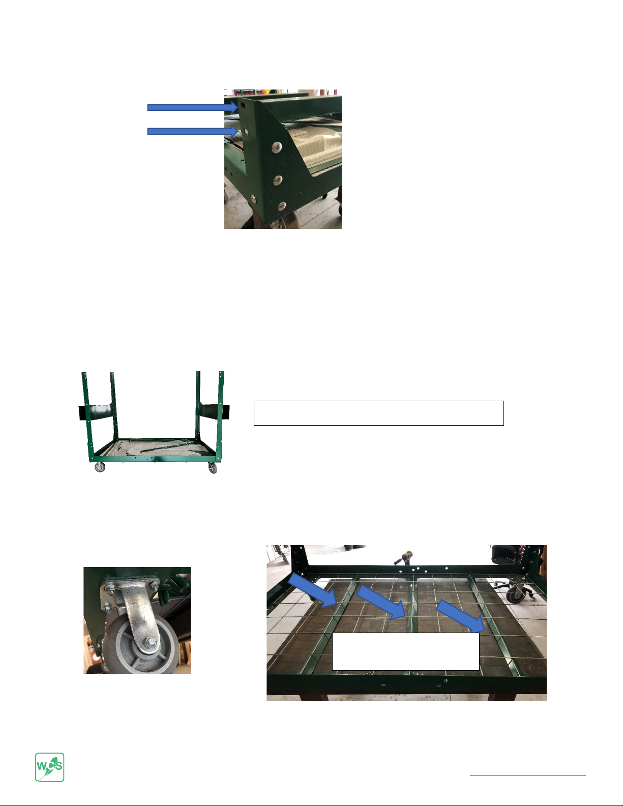
Orientation of Dumpster –Front is determined by the locking left front wheel and the front left and right vertical corner
posts are lower than the back.
Parts List
Parts Packed in Dumpster
5- bag and lid support rods (longest rod is used for the top, back bag support.)
1 - lid support rod
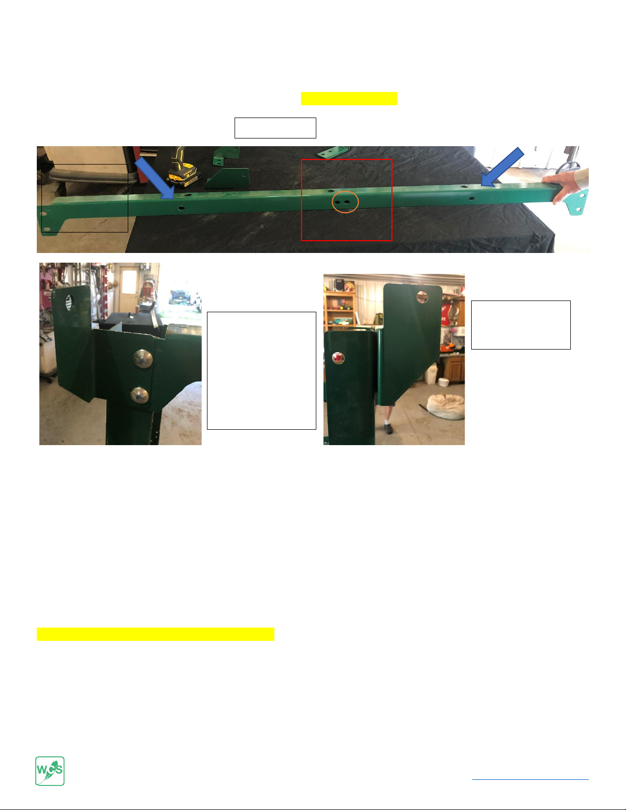
1 - left front vertical support
1- center front vertical Support
1 - right front vertical support
1 - back right vertical support
1 - back left vertical support
2- top end bag support rails (Concave Bars)
2- bottom end bag support rails (Flat bars)
2 - bag protectors
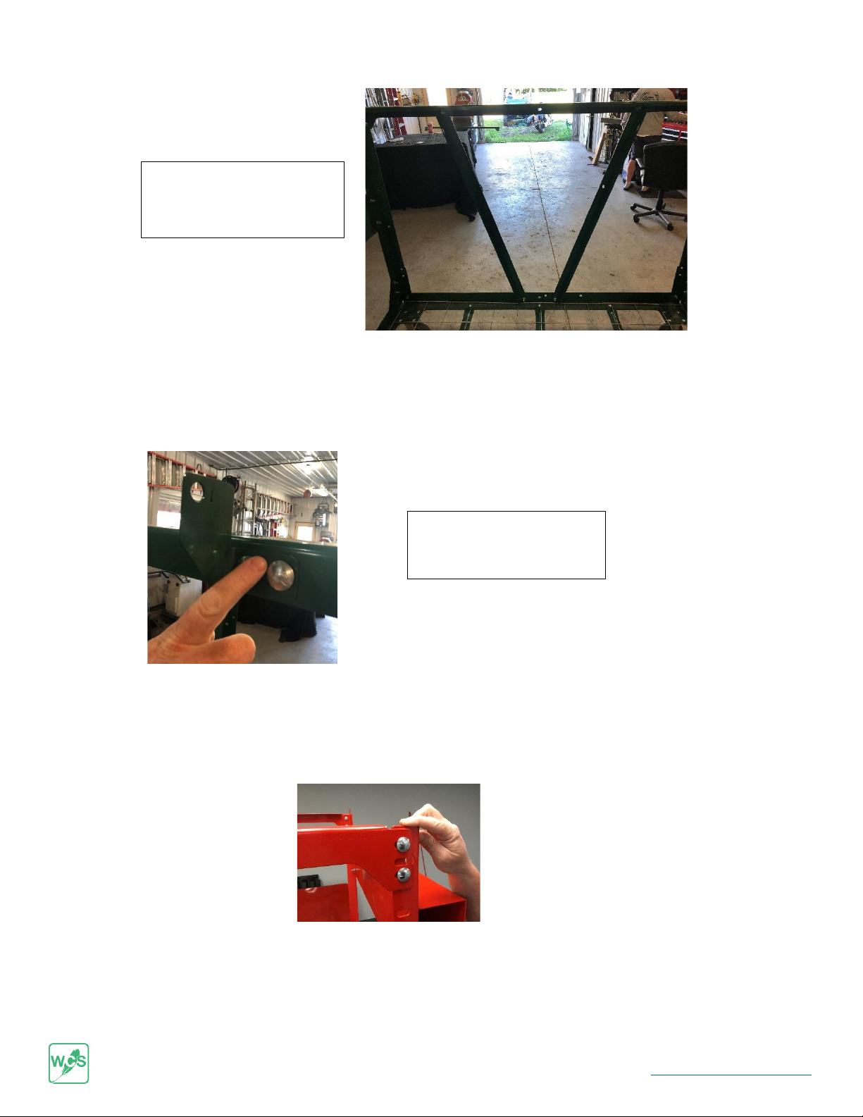
1 - Front panel
2 - Lids
Hardware Bag
5- cotter pins
18- 1-inch bolts
18- nuts
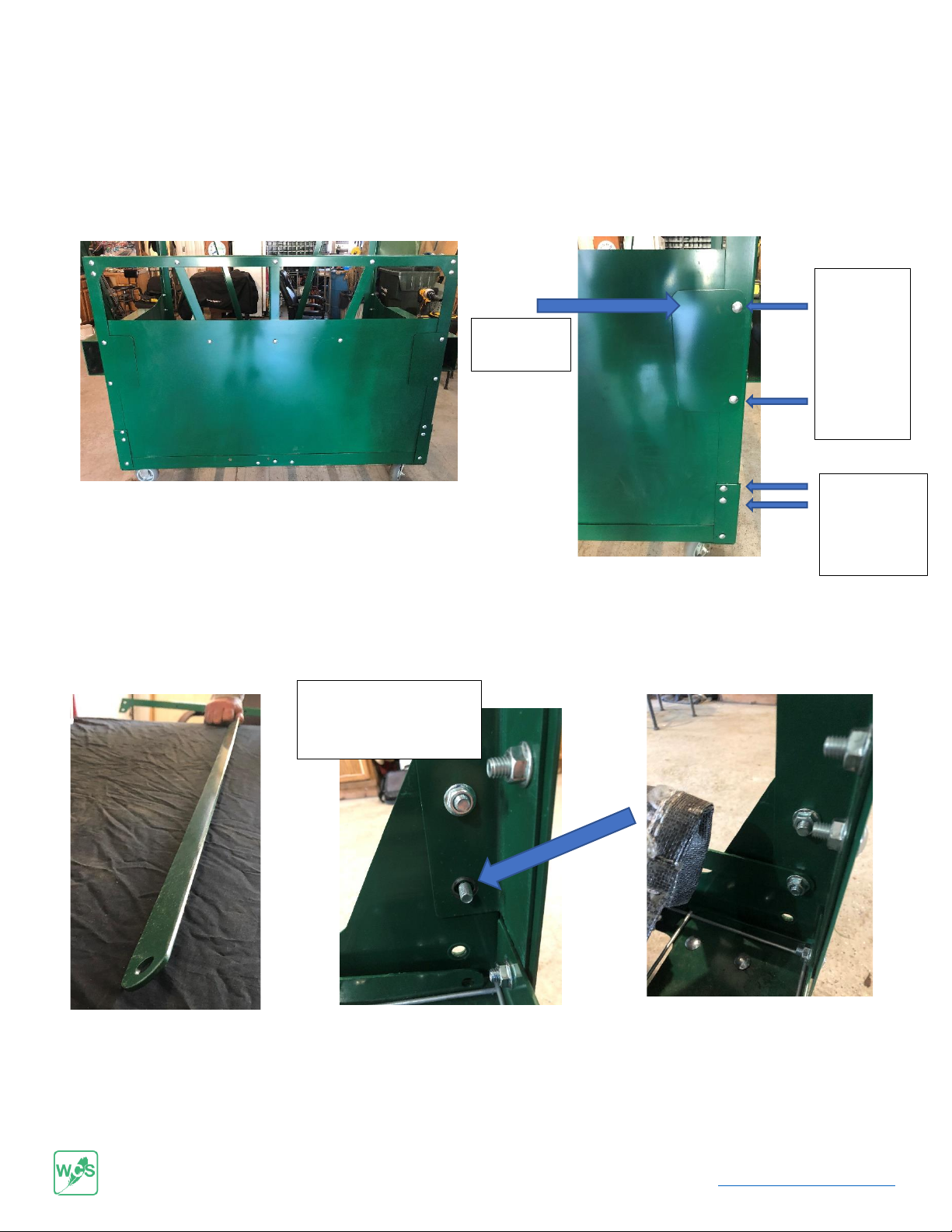
Attached to Dumpster When Shipped
2 - left and right lid brackets (Shown at Right)
1 - middle lid bracket (Shown at Right)
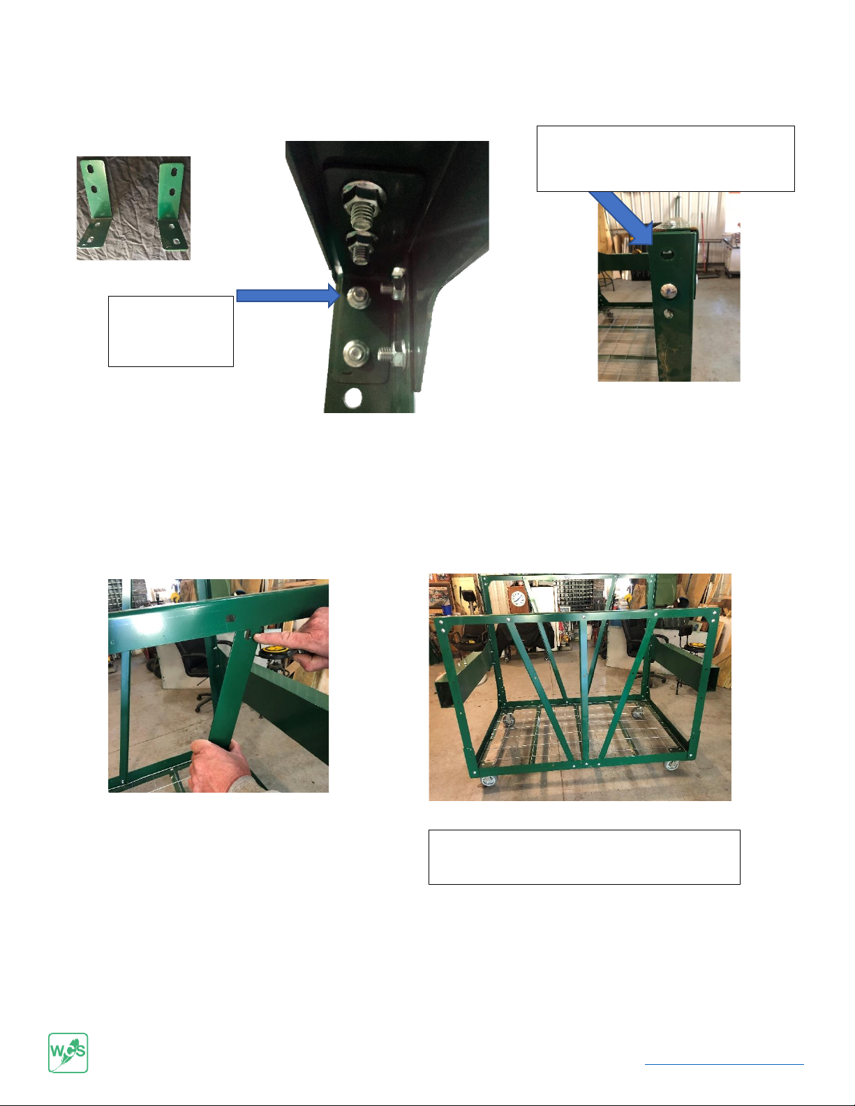
2 –Front Corner “L” Brackets