Weatronic BAT 60 User manual


User Manual
Subject to change - No liability for errors and printing errors - September 2014
weatronic ® GmbH - Schmiedestraße 2A - 15745 Wildau
2
Introduction
Thank you for hooking up with this fantastic product to fly, drive and enjoy your model. Welcome to the weatronic family!
The development, production and assembly of all weatronic products is based in Germany. All components are tested with the highest German standards. During the development process reliability and
noise immunity are considered the most. Quality and reliability are the top priorities for our specialists in the field of digital signal processing and satellite communications. Their knowledge and close
cooperation with universities take care to be all the time up to date.
Please always check www.weatronic.com for more information about the BAT 60. Under the section support videos you will find all the small videos mentioned here in this manual. Keep the manual up to
date by frequently checking our webpage. Also we strongly recommend to read this manual completely in order to avoid any misuse. Especially always mind the safety instructions.
Main features of the new weatronic® transmitter BAT 60
•A bidirectional and true redundant 2.4Ghz system with 2 integrated patch antennas is
providing a tremendous operation distance (up to 3 miles, if unobstructed view)
•22 programmable controls and the possibility to control up to 64 servos
•Huge 5inch color LCD touch screen
•Innovative new weatronic programming style - no more limits to channels or
predefined and fixed structures
•Intelligent Battery Management System
o 4 Li-Ion batteries and each with 3000mAh capacity (brand manufacturer)
o Build in charger including individual cell monitoring for capacity evaluation
o Huge charging voltage range (10-20 volts)
o Additional measurement of temperature and current
o 3 batteries are connected parallel as the main power supply
o One battery is always reserved as a 25% reserve, this job is rotating - thus ensuring
uniform aging of all 4 batteries
o Charging during flight is possible
o Each battery has its own overload protection
o Authorization under EU law
•Separation of the Flight Controller and the Linux PC - the separation of this two
elements ensures maximum safety and offers the user additional benefits
•Reliable quality control – each single transmitting module is individually tested before
installation (transmitting and receiving performance)
•Using 80 frequency channels (maximum use of all frequency channels allocated in the 2.4
GHz band)
•Frequency channel hopping rate: 100 Hz (every 10 ms - 100 times per second)
•Built in Wi-Fi, the user interface can be displayed simultaneously on every standard browser
via Wi-Fi.
•Newly designed, innovative sticks
o Proprietary gimbals design with 9 ball bearings
o Innovative throttle- / brake handle concept
o easy and quick adjust of all 4 modes
o tension, tension behavior and ratchet behavior individually adjustable
o interchangeable sticks and lengths
•3D Hall sensors on the sticks
o Wear-free and thus unsusceptible to faults
o 100% digital solution (digital interface - no loses by digitizing)
o True 12-bit resolution, 4096 points
o Temperature Compensated
•Data recording on SD memory card
•External connections are recessed, thus better protection against bending and impurities:
o 2 USB Ports
o 1 x 3,5 mm jack for stereo headphones
o 1 x 3,5 mm jack for PPM-signal
o 1 x USB mini B
o charge plug
•Audio output through built-in speaker
•Integrated GPS offers UTC time stamp and features like the “look and find” option.
•Over 1,000 model memory (only limited by capacity of the SD-card)
•weatronic® is the first manufacturer, who implements the ETSI standard EN 300 328 V1.8.1,
"listen before talk"
“MADE IN GERMANY”
NOTE: All grey marked software options are still under field-testing and are not yet activated.

Subject to change - No liability for errors and printing errors - September 2014
weatronic ® GmbH - Schmiedestraße 2A - 15745 Wildau
3
Content:
1. Scope of supply .................................................................... 4
2. Safety instructions............................................................... 5
3. Technical data........................................................................ 6
4. Care instructions .................................................................. 7
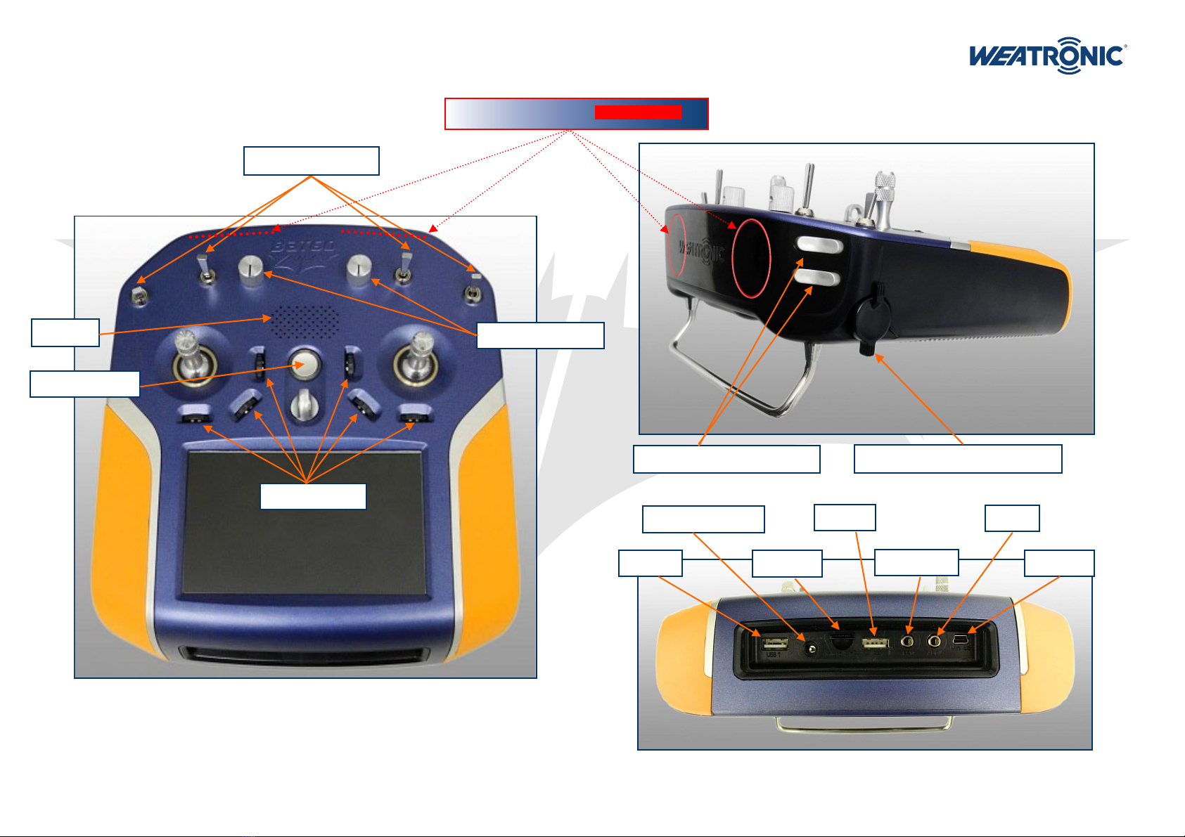
5. General overview................................................................. 8
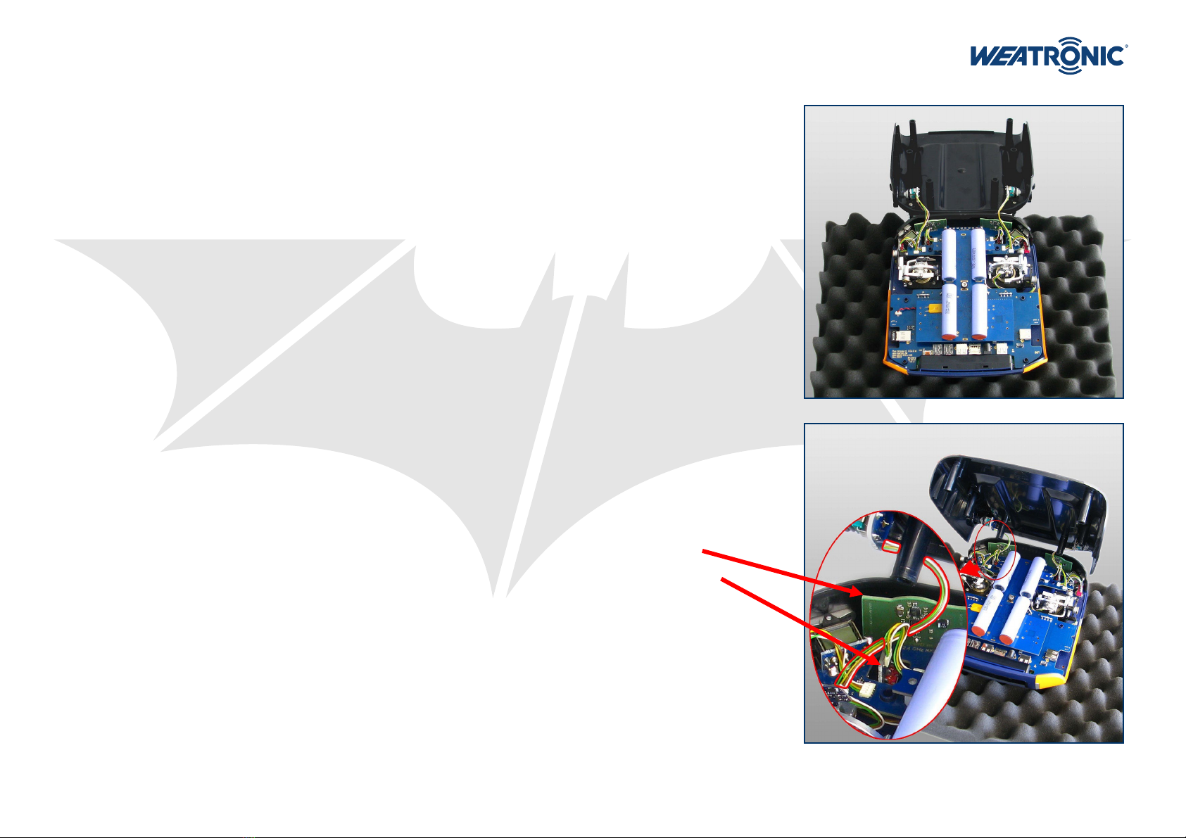
6. Overview about internal electronics............................... 9
7. How to open and close the BAT 60 ................................ 10
7.1. Open it................................................................................. 10
7.2. Close it ................................................................................. 10
8. Mechanical stick adjustment........................................... 11
8.1. How to adjust the “spring force” ...................................... 11
8.2. How to adjust the “feedback characteristics” .................. 11
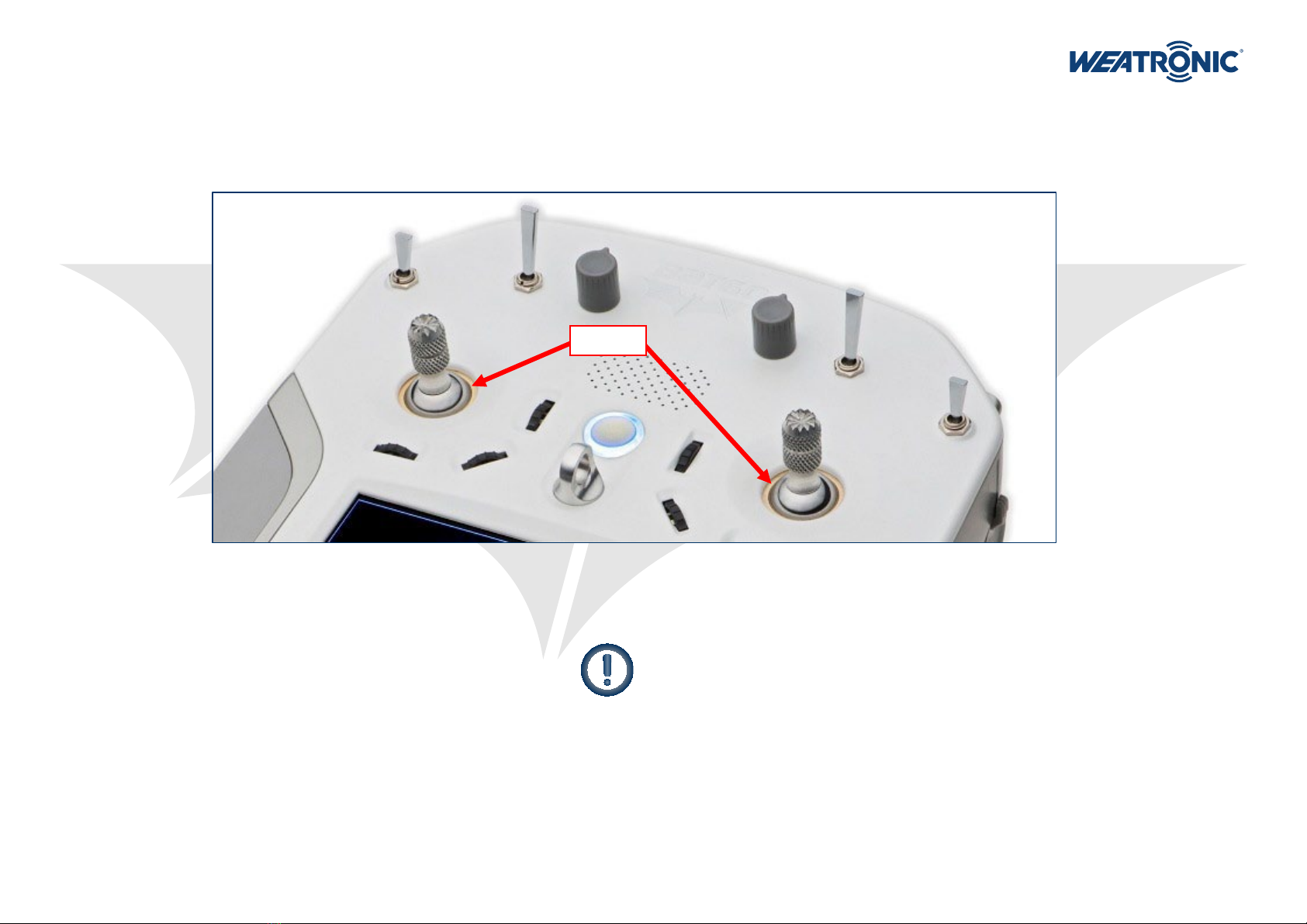
8.3. How to change the stick length......................................... 12
8.4. Laying of internal stick cables............................................ 13
9. Mechanical toggle switch adjustment.......................... 14
10. Hardware extras ................................................................. 16
11. Charging BAT 60 (10 - 19 Volt)......................................... 16
12. LED status information..................................................... 16
12.1. Transmitter is switched off and charging.......................... 16
12.2. Transmitter is switched on.................................................. 16
13. How to switch on/off......................................................... 17
13.1. ON .................................................................................. 17
13.2. OFF .................................................................................. 17
13.3. RESET .................................................................................. 17
14. Interface ............................................................................... 18
14.1. The display .......................................................................... 18
14.2. TOP INFO ROW.................................................................... 18
14.3. NAVIGATION ROW .............................................................. 19
14.4. Common interface symbols ................................................ 19
14.5. Common “pop-up” menus ................................................. 19
15. Calibration of potentiometers and sticks .................... 20
16. Software and firmware UPDATE..................................... 20
16.1. Update process of BAT 60 .................................................. 20
16.2. Update of weatronic receivers........................................... 20
17. Binding process .................................................................. 20
18. RC-equipment installation in your model.................... 20
19. “setup wizard” - how to add a new model ................ 21
19.1. 1st step: Model Configuration ........................................... 21
19.2. 2nd step: Select Stick Mode ............................................... 21
19.3. 3rd step: Receiver Configuration....................................... 21
19.4. 4th step: Servo Configuration graphic view ..................... 21
19.5. 5th step: Servo Configuration list view ............................. 21
20. weatronic programming philosophy ............................ 22
21. Menu structure ................................................................... 23
21.1. Model Settings .................................................................... 23
21.1.1. Model Configuration.................................................. 24
21.1.2. Receiver Configuration .............................................. 24
21.1.3. Servo Configuration ................................................... 25
21.1.4. Functions ..................................................................... 26
21.1.4.1. Function name ......................................................... 26
21.1.4.2. Function Setup ......................................................... 26
21.1.4.2.1. Flex Rate ................................................................ 26
21.1.4.2.2. Flex expo................................................................ 26
21.1.4.2.3. Flex Differential..................................................... 26
21.1.4.2.4. Fail Safe Pos. .......................................................... 26
21.1.4.2.5. Duration................................................................. 26
21.1.4.2.6. Curve Edit............................................................... 27
21.1.4.3. Control Assignment ................................................. 28
21.1.4.4. Trim Setup ................................................................ 28
21.1.4.5. FMO (Flight mode offset) ........................................ 28
21.1.4.6. Servo Assignment..................................................... 28
21.1.4.7. Gyro .......................................................................... 28
21.1.5. Function Mixers .......................................................... 29
21.1.6. Flight Modes ............................................................... 29
21.1.7. Virtual Switches .......................................................... 30
21.1.8. Timers .......................................................................... 30
21.1.9. Limiter ......................................................................... 30
21.1.10. Screen Adjustment ..................................................... 31
21.1.11. Control Map................................................................ 31
21.1.12. Servo Monitor ............................................................. 31
21.2. General Settings ................................................................. 32
21.2.1. Calibration .................................................................. 32
21.2.2. File Manager ............................................................... 32
21.2.3. Firmware Versions ...................................................... 32
21.2.4. PreFlight Test .............................................................. 33
21.2.4.1. Range Test ................................................................ 33
21.2.4.2. Failsafe Test .............................................................. 33
21.2.5. User Settings ............................................................... 33
21.2.6. Stick Control Config ................................................... 34
21.2.7. Unit Selection.............................................................. 34
21.2.8. Volume control ........................................................... 34
21.2.9. Brightness control....................................................... 34
21.3. Model Management........................................................... 34
21.3.1. Change model............................................................. 34
21.3.2. Add new model .......................................................... 34
21.3.3. Copy model ................................................................. 34
21.3.4. Delete model .............................................................. 35
21.3.5. Import/export.............................................................. 35
22. Declarations of Conformity............................................. 35
23. Disclaimer of warranty / damages................................. 36
24. Disposal instructions for countries within the EU..... 36
25. You need help? ................................................................... 36
BAT 60 - User Manual

BAT 60 - User Manual
Subject to change - No liability for errors and printing errors - September 2014
weatronic ® GmbH - Schmiedestraße 2A - 15745 Wildau
4
1. Scope of supply
•BAT 60 ( 4 different colors schemes are available: white / black / silver / blue )
•Robust aluminum case with foam inlay
•Switching Power Supply with UK/US/EU/AU adapter
•Allen key set
•weatronic “feedback part” standard set
( ST, SL, CD, CS, CH, one of each, check chapter 8.2 for more Info )
•Neck strap
•“setup wizard” Quick Guide (printed)

BAT 60 - User Manual
Subject to change - No liability for errors and printing errors - September 2014
weatronic ® GmbH - Schmiedestraße 2A - 15745 Wildau
5
2. Safety instructions
The weatronic ® 2.4 Dual FHSS - Remote Control System has been developed exclusively for the operation of radio-controlled model cars, model aircraft and ship models and is only allowed for this use.
weatronic ® assumes no liability for improper use. Young people under 14 years may operate remote controlled models only under adult supervision. Please operate your model only on intended areas.
Always be aware of the local airfield rules, in doubt ask local club members. Be careful during operation of your model. Even small models can be very harmful and cause serious injuries and death! Especially
rotating blades and propellers or hot exhausts can easily cause injuries. Never operate your model if your model is not fully functioning.
Be considerate to other pilots and arrange with each other. Stay in reach to other pilots, so you can communicate about your landing and take-off approaches in order to avoid accidents. Always stay away
from Non-Fly zones and never fly over spectators or any persons who are near the airfield.
The weatronic ® 2.4 Dual FHSS system can be used simultaneously with other 2.4 GHz systems, and also with 35/40/72 MHz systems. The frequency control check is no longer necessary within the 2.4GHz
Band. More than 120 weatronic ® 2.4 Dual FHSS systems can simultaneously be operated.
NOTICE
Before operation always perform the following routine checks:
•Fix your model in place.
•Keep a safe distance.
•Mind bystanders, especially spectators who are not aware of the potential dangers!
•Indicate sources of danger, such as rotating blades and propellers or the hot exhaust of jet-turbines, etc.
•First of all switch on your transmitter. Then turn on the receiver in the model.
•Before using your model test all functions, in particular their moving direction and all surface deflections should be checked. Do not operate if this is not correct!
•Check the failsafe-position and check the antenna position inside the model. Do not operate if this is not correct!
•Also check your batteries to be sufficiently charged. Do not operate if this is not correct!
NOTICE
Consider the following points in order to charge your radio in a perfect way:
•Always use a proper power supply to charge your radio. The power supply which comes with your radio is perfect. weatronic assumes no liability for damage due to a wrong
power supply. car adapter is also available. Just contact your support dealer or weatronic directly for more information.
•Never modify the internal battery board in any way.
•During charging never open the case of the radio.
Charging is only recommended if outside temperature is between 0° and 35° Celcius.
Do not short-circuit the battery, as it may generate heat.To avoid short-circuiting, do not let the battery come in contact with metal objects at any time.
Do not put the battery into a fire, as it may swell or explode.
Do not use near any type of heat source. When battery leaks electrolyte or emit a strange smell, discontinue use and move battery away from the heat source.
Be aware of rotating blades or propellers! Unintended activating of the motor is possible.
They can be very harmful and cause serious injuries like cutting fingers or even cause death.
ALWAYS remove such rotating parts from the motor to avoid danger especially during programming and adjusting your model.
ALWAYS take care of casual bystanders, because they don’t know about the potential danger!
Since the device contains small parts which can be swallowed,
an increased level of care is required, especially for babies and infants.
Not recommended for children under 3 - small parts may be inhaled or swallowed.
•
•
•
•

BAT 60 - User Manual
Subject to change - No liability for errors and printing errors - September 2014
weatronic ® GmbH - Schmiedestraße 2A - 15745 Wildau
6
3. Technical data
•transmission: adaptive frequency hopping operation with “listen before talk” function
•frequency range: 2.401 to 2.4835 GHz
•hopping-frequencies: 80
•hopping-speed: 10ms / 100Hz
•receiving Sensitivity: -100 dBm
•output Power: 20 dBm (100 mW)
•antennas: 2 x patch antennas (angle of radiation > 180°)
•resolution of the servo outputs: 4096 steps
•“channels”: Not limited to “channels” anymore - check chapter 20 for detailed information about the new weatronic programming philosophy
•display: 5 inch color LCD with a capacitive touch screen and a resolution of 800 x 480 pixel
•battery: 4 x Li-Ion à 3000mAh with build in charger and battery management
•power supply: 10,0 - 19,0 Volt
•temperature range: -10 °C to +60 °C / 14°F to 140°F, non-condensing
•dimensions: 218 x 195 x 55 mm, 8,58 x 7,68 x 2,16 in (L x W x H)
•weight: 1,3kg, 45,8oz
•firmware: upgrade via USB
•software: upgrade via USB
•extras: integrated GPS, built in Wi-Fi
•optional extras: Bluetooth, Vibration, stick switches
•stick technology: Hall sensors and adjustable stick characteristics
•stick resolution: 12bit encoding of the magnetic field
•Audio output: Internal speaker, 3,5mm stereo audio out
•Connectors: 2 x USB, 1 x USB mini, 3,5mm jack for PPM in/out signal, 3,5mm jack for headphone, standard charge plug, micro SD card slot
•weatronic disposal number: 905 344 19 WEEE
•FCC ID: W3X2754-60
•IC : 11388A-600

BAT 60 - User Manual
Subject to change - No liability for errors and printing errors - September 2014
weatronic ® GmbH - Schmiedestraße 2A - 15745 Wildau
7
4. Care instructions
•Please use a soft and damp cloth for cleaning the case and the display.
•We recommend keeping the two sticks clean. Usually you don’t need to oil the center ball of the stick! However we recommend using a very tiny amount (one drop maximum)
of synthetic lubricant which does not resinify or polymerize. Please use a cloth and apply very little. Call us if you have any questions.
•Whenever the radio is used in humid air please let it dry properly before switching it on again.
•If your BAT 60 got somehow wet inside or outside please switch it off and let it dry completely before switching it on again.
•Keep your BAT 60 clean, dry and avoid dusty environment.
•Do not block the antennas with any kind of electro conductive material. This includes also parts of the body. The Antennas are located underneath the black front cover. Check
the next page: there you see the exact place
Many components of your radio could be influenced by magnetic waves.
So please keep away any strong magnets.
•If you want to store your BAT 60 for a longer period, please charge it completely, check if it is dry and place it inside the aluminum case. Then keep it in a cool and dry place and
avoid direct sunlight.
center ball

BAT 60 - User Manual
Subject to change - No liability for errors and printing errors - September 2014
weatronic ® GmbH - Schmiedestraße 2A - 15745 Wildau
8
USB „1“
DC in (10 -19 Volt )
mini USB
USB „2“
PPM (in/out)
Audio
micro SD
5. General overview
REAR VIEW
SIDE VIEW
TOP VIEW
TOP Potentiometer
SIDE Potentiometer (left and right)
Rocker Switches (left and right)
ON / OFF Button
Rotary Encoder
Speaker
2 internal Patch-antennas DO NOT COVER!
Toggle Switches (TS)

BAT 60 - User Manual
Subject to change - No liability for errors and printing errors - September 2014
weatronic ® GmbH - Schmiedestraße 2A - 15745 Wildau
9
6. Overview about internal electronics
There are 3 main electronic PCBs (printed circuit board)
•The Main Board is the biggest one and there are several
small PCB soldered to it. Like the two antenna PCBs and
the rotary encoder PCBs and the front switches. The
Main Board takes care about the transmission and is the
most important component.
•The Battery Board takes care about the 4 Li-Ion cells. It
contains a charger and the capacity surveillance for
each cell. Furthermore it is monitoring electric
overloading, temperature and current. The battery
management is using 3 cells for operating the system
and it keeps the remaining one as a reserve. The safety
cell is selected by the system randomly on each start up.
•The Linux / Display board (LINDIS) contains the Linux
computer which provides the interface to the user!
Anyhow it is not necessarily needed to operate a model
with the BAT 60.
Also there are some more additional smaller PCBs
•Each stick includes 2 hall sensor boards. All cable
connections form the hall sensors boards to the
Main Board are the most significant cable connection
inside the BAT 60.
•There are some small PCBs at each toggle switch and at
the two side potentiometer in the bottom case.
BATTERY BOARD
LINDIS
MAIN BOARD

BAT 60 - User Manual
Subject to change - No liability for errors and printing errors - September 2014
weatronic ® GmbH - Schmiedestraße 2A - 15745 Wildau
10
7. How to open and close the BAT 60
7.1. Open it
•First of all switch off and please be aware that all internal electronics components are treated according to the
mandatory formalities of how to use electromagnetic components.
•Remove the top foam inlay of the aluminum case and place the BAT 60 upside down.
•Now use the 2.5 mm Allen key and open all of the 6 (M3x20mm) screws at the bottom.
•Lift the bottom case part vertical up for about 1cm, now flip it over to the front (beware of the two cables).
•If you want you could detach the 2 cables to the bottom part (attached to the 2 side potentiometers),
anyway we recommend to leave them attached and place the bottom part like at the picture on the right.
•There is also a small video how to open the case at our webpage.
7.2. Close it
•After you are done with your adjustments it is time to close the case. Follow the steps precisely. There is also a
short video available.
•We recommend that you use again the top inlay of the aluminum case and place the top part upside down.
•First of all please visually check all cables one more time and make sure that they are all locked in their
corresponding connectors properly. Then press each of them one more time firmly. Just to make sure. Thanks.
•If you removed the cables to the two side potentiometers please reattach them now. Also double check them.
•Now slowly flip the bottom part above the top part and make sure that the 2 cables to the bottom
potentiometers are placed in the right way.
The cables have to be placed between
the antenna board
and the toggle switch.
•Now close the case. Please check that there are no cables jammed.
•Finally screw all 6 (M3x20mm) with the 2,5mm Allen Key. We recommend a maximum torque of 80Ncm (hand
tight).
•Switch on and if necessary navigate to the calibration menu (general settings) and calibrate the controls (see
chapter 15.).

BAT 60 - User Manual
Subject to change - No liability for errors and printing errors - September 2014
weatronic ® GmbH - Schmiedestraße 2A - 15745 Wildau
11
8. Mechanical stick adjustment
The weatronic stick is a revolutionary design. It allows you to adopt each of the 4 axes to your personal needs. You can adjust the “spring
force” and the “feedback characteristics”. Check also the “weatronic-feedback parts“ description at our webpage.
Mainly you will open the case to customize the mechanical stick characteristics. Or just simply change the stick mode. There are 4 different
common stick modes. Called Mode 1 to 4. Check the picture on the right. You can order your BAT 60 with Mode 1 or Mode 2.
As the Motor/Butterfly is mostly used with the so called ratchet behavior, it is necessary to interchange the “feedback part” for Elevator and
Motor /Butterfly when ever you want to change from Mode 1/Mode 3 to Mode 2/Mode 4.
8.1. How to adjust the “spring force”
•Very easily done by simply choose one of the 8 gaps on the so called “spring arm”.
•The more you put the spring “upwards” the more tension will be applied. So you
can very easily adjust the restoring force for each axis.
•Never modify the spring in any way. If you have any problems here, don’t hesitate
to contact us.
8.2. How to adjust the “feedback characteristics”
•First of all release the tension of the spring by hooking of the spring (see the green
arrows).
•Then flip the “spring arm“ away (see the red arrow on the lower right picture).
•Use the 2mm Allen Key and unscrew the white “feedback part” (see the blue
arrow).
•Now choose your preferred new “feedback part”, there are 7 different ones (see
the mark on the outer side of every part):
o CN: CenterNormal (linear force)
o CS: CenterSoft (progressive or increasing force)
o CH: CenterHard (regressive or declining force)
o ST: STep (the “ratchet”)
o SL: SLide (no “ratchet”)
o CD: CenterDetend (like the “SL” but with a sense able center mark)
o MA: MixA (combination of “ratchet” and “spring-loaded”)
o MB: MixB (mirror part of MA)
•Screw the new “feedback part” back in place, the mark has to point outside.
•Tight the screw slightly hand-tight (maximum of 40Ncm). Make sure the plastic part
has a completely seamless fitting to the aluminum part.
•Finally flip back the “spring arm” and attach the spring back in place.

BAT 60 - User Manual
Subject to change - No liability for errors and printing errors - September 2014
weatronic ® GmbH - Schmiedestraße 2A - 15745 Wildau
12
The lower edge and the
backside of the plastic part has
zero tolerance to the aluminum
part, this ensures a perfect
alignment. If there is an excess
on the back edge of plastic part
please remove it carefully, a
slight chamfer is recommended.
The upper “feedback part”
surface (green arrow) where the
“spring arm” ball bearing is
touching is extremely critical.
Even the smallest scratch or
dent is clearly recognizable as a
“scratchy” feeling on the stick.
So please take care here. The
surface should be smooth and
clean like a mirror. Replacement
parts are available.
8.3. How to change the stick length
This is very easy. The sticks are like a screw.
Just unscrew them and replace them with a different length (23mm / 28mm / 38mm).
Please do not use any tools here. Again hand tight is enough.
screw in
screw out

BAT 60 - User Manual
Subject to change - No liability for errors and printing errors - September 2014
weatronic ® GmbH - Schmiedestraße 2A - 15745 Wildau
13
8.4. Laying of internal stick cables
The cables to the Stick PCBs (PCB = printed
circuit board) are very important!
Please always check a proper locking of the
cables to the connectors and also make sure
that the cables are placed in the right way!
See the picture on the right.
Whenever you encounter any issues or any
visual damage to one of the cables or the
stick itself
do NOT
operate your model.
Never modify the stick in any way! Contact
our service for repairs.
See here a picture of the two stick PCBs:
The bigger one is the external and fixed
“hall sensor board” and the small one is the
internal one. The small PCB board is also
providing an additional connector, which
will be used if there are stick switches or
similar controls added.

BAT 60 - User Manual
Subject to change - No liability for errors and printing errors - September 2014
weatronic ® GmbH - Schmiedestraße 2A - 15745 Wildau
14
9. Mechanical toggle switch adjustment
•You can customize the 4 top toggle switches (TS1 to TS4). See also the top view picture at chapter 5.
•There are different ones available. Please check our web shop for detail information.
•You can apply different angular positions to each switch.
•Just choose one of the 3 positions on the case (see the top right picture - the red lines are marking the 3 different angular positions).
•Align the PCB boards in the right direction. Check the next page for detailed information!
•Use a 9mm wrench to mount the dress nut. Be careful with
case surface. The paint can be scratched.
Be careful, hand-tight is enough! The plastic case or
the pin (marked with the red arrow) which prevents
the switch to turn can be easily damaged.
Also make sure that the cables are not twisted and
the connectors are placed right!
The length of the cable is 50mm.

BAT 60 - User Manual
Subject to change - No liability for errors and printing errors - September 2014
weatronic ® GmbH - Schmiedestraße 2A - 15745 Wildau
15
The backside (see the
lettering, which is on
the backside) of the
two blue switch mini
boards have to point
to each other! The
picture shows only
one side. The other
side must be arranged
identical.

BAT 60 - User Manual
Subject to change - No liability for errors and printing errors - September 2014
weatronic ® GmbH - Schmiedestraße 2A - 15745 Wildau
16
10. Hardware extras
The BAT 60 can be upgraded with some really nice features.
•There is the option to install a vibration motor, which can indicate warnings or simple information. Please note that the vibration comes not as a standard with your BAT 60
•There is also an option to install a Bluetooth chip to the Main Board. This will be available later as an option.
•The Wi-Fi dongle is a standard and connects your BAT 60 to any Wi-Fi network. If your BAT 60 is connected to the same network as your PC you will be able to access to the radio
via your browser and program simultaneous from both devices. We recommend that you use one of the devices as the “main” programming input and the “second” one as a
control display. Because it will be confusing if you change values for one “item” from 2 different sources. Please consider a detailed instruction at our webpage.
11. Charging BAT 60 (10 - 19 Volt)
The BAT 60 handheld radio is equipped with 4 Li-Ion cells which are maintained and charged by an internal charge controller. This controller checks temperature, voltage, current, and calculates the capacity
of each cell. Also it takes care about the entire charging process. Whenever there is a voltage between 10 and 19 Volts applied to the power jack the controller starts to charge the cells.
So in order to charge your BAT 60 easily attach the switching power supply which is provided with your radio. You can get some car adapter at our shop too. Also you could use any other voltage source or
external battery. So for example a 3s Li-Po battery could do the job. Just be aware that the battery pack will get discharged down to 10 Volts (default settings). If you use another voltage source than
provided by weatronic, weatronic can not assume any liability for damage due to a wrong power supply or source.
Under “General Settings” you find the battery management menu and there you can check the status of all cells and adjust the cutoff voltage for the external power supply.
Charging during operation/flight is possible.
12. LED status information
The LED ring around on/off button shows you some basic system status:
12.1. Transmitter is switched off and charging
•
Green
: fully charged
•Orange: more than 80% charged
•
Red
: <80% charged
•Red blinking: recovering of low battery status, after around 15 minutes, it should be solid.
If not please contact our service.
12.2. Transmitter is switched on
The slow pulsing blink shows the state of the BAT 60 batteries:
o
Blue
: more than 20% remaining
oOrange: less than 20% remaining capacity
o
Red
: less than 10% remaining capacity
o Red rapid flashing: Running on spare battery!
Do not operate any models anymore! Charge the radio now!
The short red blink code in between shows the receiver status (Please consider chapter 21.1.2):
o Nothing: everything Ok
o 1x red: backchannel threshold warning
o 2x red: uplink threshold warning
o 3x red: low battery threshold warning
•
•

Subject to change - No liability for errors and printing errors - September 2014
weatronic ® GmbH - Schmiedestraße 2A - 15745 Wildau
17
BAT 60 - User Manual
13. How to switch on/off
13.1. ON
Pressing the on/off button for about 0.5 seconds will activate the BAT 60 and will start the boot process of the Linux PC. The booting of the Linux will take some
seconds. Nevertheless you can fly with the last used model within less than one second with all settings, Flight modes, etc.
Linux boot is finished when you see the home screen. Now you can do changes on the settings, change model, etc…
13.2. OFF
•Tab the “shutdown” symbol at the navigation row or press the ON-OFF button continuous for more then 3
seconds.
•There will be an info pop up at the screen and the on/off button will get red. If you pressed the ON-OFF button for 3 seconds release the button
now.
•Now just press the on/off button once for about 0.5 seconds and you will see the confirmation pop up about shut down process of the BAT 60.
If there is still a connection to a receiver, you have
to confirm (just tab ignore) before you can switch
off.
13.3. RESET
Whenever there is a problem to switch the radio off, you can do a hard reset. Please do this only in case of real need.
Press the ON/OFF button for at least 15 seconds, the LED around the button will start to flash rapidly orange.
Now release the button and the LED will change the color to
Red
. Now you have 3 seconds to press the button again and the BAT 60 will turn off.
Consider that there is maybe some normal status information indicated by the LED. This is maybe
interfering with the rapid orange or red flashing.
If a hard reset is performed it is possible that some of the latest setup changes are not saved and
maybe discarded.

BAT 60 - User Manual
Subject to change - No liability for errors and printing errors - September 2014
weatronic ® GmbH - Schmiedestraße 2A - 15745 Wildau
18
14. Interface
Here you see a screenshot of the home screen. The “TOP INFO ROW”,”NAVIGATION ROW” and the rotary encoder position indicators are labeled.
Swipe left or right to reach the telemetry screens.
Go to chapter 21.1.10 for more information.
14.1. The display
The display of BAT 60 is a capacitive touch screen. This means it recognizes the presence of your finger. Pressing hard on the screen will not improve functionality but reduce
lifetime. Furthermore it will not recognize any metal, wood, plastics, etc. If you don’t want to use finger for touch please buy a special pen for capacitive touch screens. Also be
aware that the display is affected by temperature. If it is very cold it is normal that the refresh rate of the display is slower than normal.
14.2. TOP INFO ROW
The information row on top which is shown in almost all menu screens
informs you about the current model, flight mode as well as the remaining
expected runtime. The battery symbol on the top right corner gives evidence
about the battery status
Swipe Swipe Swipe

BAT 60 - User Manual
Subject to change - No liability for errors and printing errors - September 2014
weatronic ® GmbH - Schmiedestraße 2A - 15745 Wildau
19
14.3. NAVIGATION ROW
The navigation row on the bottom is used to enter the setup menus. See here the description of the symbols:
14.4. Common interface symbols
There are also some common symbols used for navigation through the interface:
14.5. Common “pop-up” menus
“Additional info”
(short link to servo
monitor, add page to
favorites menu, help)
Save settings Leave page
Abort settings Add something new to a list
Delete something from list
UNDO
“Model Settings”
“General Settings”
“Model Management”
“Home” takes
you back to the
home screen
“Favorites” will be added later
“switch off”
“Music Player” will be added later
“Notification Center” will be added later
“Help” will be added later
Value adjustment pop
-
up
Keyboard
Selection list
You can also use each of the rotary encoders to
change the value. Please note that if you assigned the
rotary encoder as a trim or as a function input, you
will change these values as well.
Press here to enter
the numpad
Scroll

BAT 60 - User Manual
Subject to change - No liability for errors and printing errors - September 2014
weatronic ® GmbH - Schmiedestraße 2A - 15745 Wildau
20
15. Calibration of potentiometers and sticks
•Go to general settings -> calibration.
•Press “Start Calibration”. Now move all sticks or potentiometer to their maximum positions.
•Moved controls are shown in red and their maximum position will be adapted to +/- 100%.
•Now press “Confirm” and move the controls to their “zero” position. Also put the throttle/brake stick to the “middle” position
before pressing “Stop Calibration”. If you are using the MA or MB “feedback part”, adjust the stick just in between the
different behaviors.
•This position will be stored as 0% by pressing “Stop Calibration”.
16. Software and firmware UPDATE
16.1. Update process of BAT 60
•Go to our download center at our webpage (www.weatronic.com) download the BAT60 firmware to your PC or MAC. Extract the compressed zip folder.
•Now copy only the “weatronic” named folder to a formatted empty USB stick.
•Insert the USB stick to one of the external USB ports at your BAT 60.
•Switch on and wait until the “home screen” appears.
•After this switch off and remove the USB stick.
•Again switch on and go to General Settings -> Firmware Versions and check if the right version is displayed.
•Now we strongly recommend to make a calibration (see chapter 15).
16.2. Update of weatronic receivers
Check the weatronic-firmware update instruction.
Please Note that the BAT 60 requires a matching firmware version for the receiver. Go to weatronic.com and download the current and matching one.
17. Binding process
Before binding process please check that there is a matching firmware installed to the receiver.
•To bind a receiver to the Bat 60 set the receiver to “Binding Mode”. Therefore have it in power off state, and then connect power supply. In between 5-30sec after power up plug
the binding jumper to the SCU red(+) and black (-). The receiver will confirm “Binding Mode” by slow blinking (1Hz) of the green LED. So as you can see, it is the same procedure
like always.
•Now navigate to the Receiver Configuration menu. Choose the correct receiver type. Press “binding” button. The “flapping-bat” pop-up shows you that the binding is in
progress. After successful binding the pop-up will disappear and the firmware version of the receiver will be shown on the screen. Also the receiver will confirm successful
binding with constant green LED.
•Remove the Binding jumper – finished.
It doesn’t matter which device is in “Binding Mode” first.
Only weatronic receivers can work with the BAT 60.
18.RC-equipment installation in your model
The correct installation of the receiver, battery, servos, electric cables and antennas is highly required to operate your model.
Avoid excessive vibration exposure and excessive heat load. Also make sure that your batteries are in perfect shape and that they are always fully charged. Take care about the voltage limits of the receiver
and the servos you are using. If you are using regulators please keep in mind that the current limit is not exceeded.
Other manuals for BAT 60
2
Table of contents
Other Weatronic Transmitter manuals