Webasto 22615 User manual

22615-76_02.docx
Instructions, Field Installation
Convert Ampro PC104 to ICOP VDX-6353RD, 50/60HZ
ABC-150
English

22615-76_02.docx
© 2019 Webasto Charging Systems, Inc. All rights reserved.
EV Test Systems is a product line of Webasto Charging Systems, Inc. Webasto and the Webasto logo are trademarks of
Webasto Charging Systems, Inc. Corporate names, trademarks, registered trademarks, service marks, symbols, and
logos stated herein are property of their respective companies. Specifications are subject to change without notice.
Images of the power cycling and test systems are representative; production models may vary. No portion of these
materials may be duplicated, used, or disclosed without prior written permission from Webasto Charging Systems, Inc.
Disclaimer: this manual includes the latest information available at the time of printing. Webasto Charging Systems, Inc.
Reserves the right to make changes to this manual and/or product without further notice. Changes or modifications to this
product not completed by an authorized service provider could void the product warranty.
These commodities, technology or software were exported from the United States in accordance with the Export
Administration Regulations. Diversion contrary to US law prohibited
Webasto Charging Systems, Inc.
+1 (866) 767-4242
evtestsystems.com

22615-76_02.docx
Warranty
Webasto Limited Warranty
Products manufactured by Webasto Inc. are warranted to the original user only to be free of defects in
material and workmanship for a period of 12 months from the date of installation, but not more than 18
months from the date of manufacture. Webasto’s liability under this warranty shall be limited to repairing
or replacing at Webasto’s option, without charge, F.O.B. Webasto’s factory, any product of Webasto’s
manufacture. Webasto will not be liable for any costs of removal, installation, transportation, or any other
charges that may arise in connection with a warranty claim. Webasto will not be liable for damage or
wear to products caused by abnormal operating conditions, accident, abuse, misuse, unauthorized
alteration or repair, or if the product was not installed in accordance with Webasto's printed installation
and operating instructions.
To obtain service under this warranty, the defective product must be returned to Webasto with proof of
purchase and installation date, failure date, and supporting installation data. Any defective product to be
returned to Webasto must be sent freight prepaid; documentation supporting the warranty claim and/or
a Return Material Authorization must be included if so instructed.
WEBASTO WILL NOT BE LIABLE FOR ANY INCIDENTAL OR CONSEQUENTIAL DAMAGES,
LOSSES, OR EXPENSES ARISING FROM INSTALLATION, USE OR ANY OTHER CAUSES. THERE
ARE NO EXPRESS OR IMPLIED WARRANTIES, INCLUDING MERCHANTABILITY OR FITNESS FOR
A PARTICULAR PURPOSE, WHICH EXTEND BEYOND THOSE WARRANTIES DESCRIBED OR
REFERRED TO ABOVE.
Some jurisdictions do not allow the exclusion or limitation of incidental or consequential damages and
some jurisdictions do not allow limitations on how long implied warranties maylast. Therefore, the above
limitations or exclusions may not apply to you. This warranty gives you specific legal rights and you may
also have other rights that vary from jurisdiction to jurisdiction.

22615-76_02.docx
Introduction
The #22615 kit is provided to allow the ABC-150 with Ampro PC104 computer board, to be converted to ICOP
VDX-6353RD, and allowing communication via CAN or/and ROS that exits in the unit. The kit contains the
following:
Item
No.
Part No.
Description
Ref
Des
Qty
1
07310
LABEL,CALIBRATION,OUTDOOR
1
2
05042
CONNECTOR, SHORTING JUMPER, SHROUD, 2PIN, 0.100(2.54), 2800VACrms, 3.0A,
-55-120C, UL E66906
3
3
05449
ASSY,MICROCIRCUIT,PROGRAMMED,AC INVERTER,ABC-150/170
U26
1
4
14286
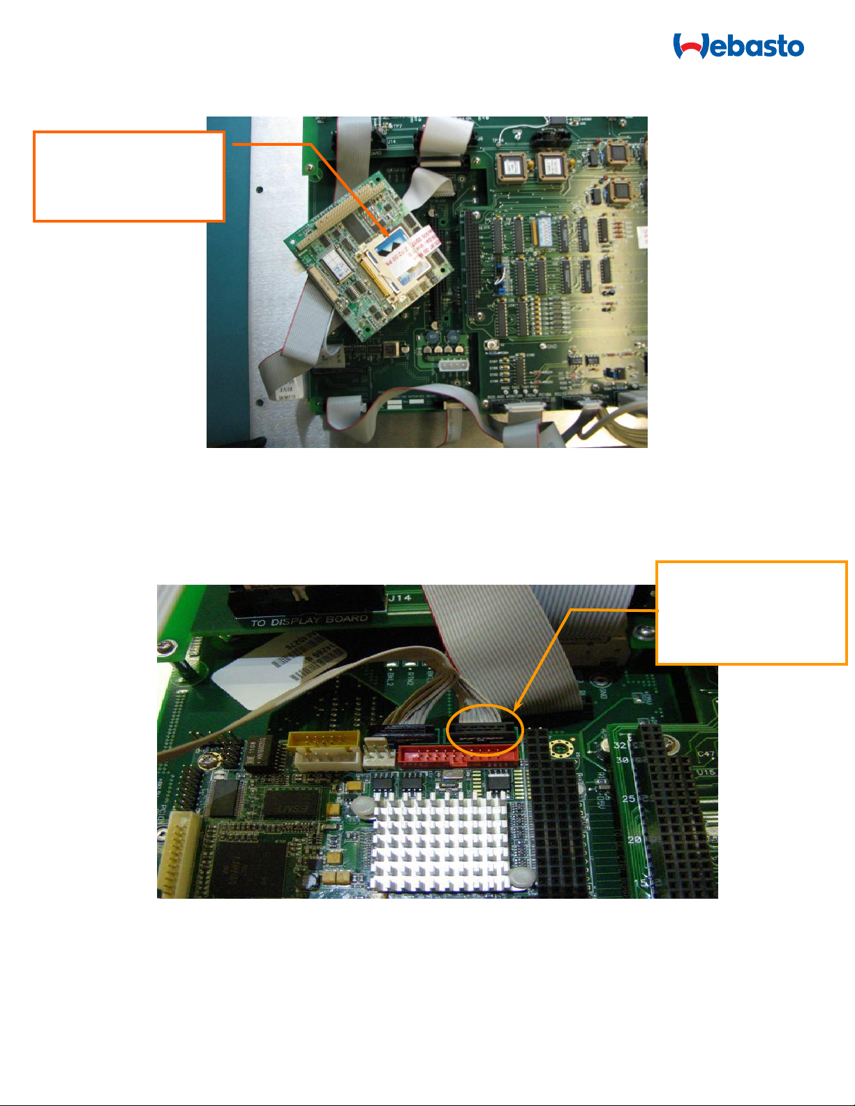
PCBA, INTERFACE, PCM/PC-104, ABC
1
5
11352
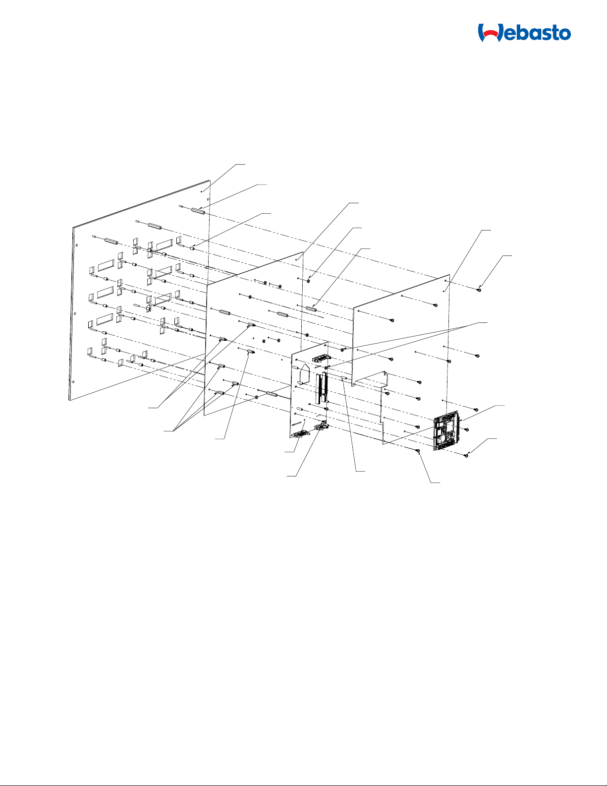
STANDOFF, FEM/FEM, RND, 4-40THR, 0.625"L, 0.187"OD, BRASS
1
6
11354
STANDOFF, MALE/FEMALE, HEX, 4-40x0.625"L, 1/4"OD, NYLON
1
7
11378
STANDOFF, FEM/FEM, HEX, 4-40X0.625"L, 1/4"OD, BRASS
3
8
11379
STANDOFF, MALE/FEMALE, HEX, 6-32X0.625"L, 1/4"OD, BRASS
2
9
11388
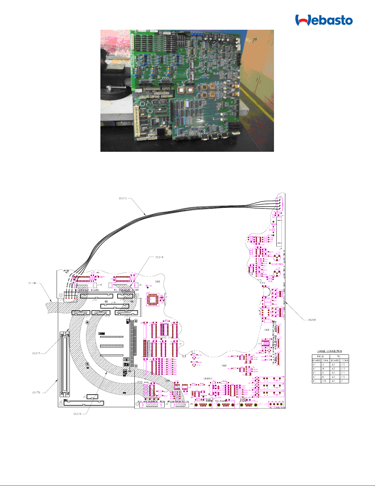
CABLE ASSY, PC104/CONVERTER CONTROL COM
1
10
29594
KIT,COMPUTER,SINGLE BOARD W PC/104
1
10.1
29595
COMPUTER,SINGLE BOARD W PC/104 AND CUSTOM BIOS,VORTEX86DX 800 MHZ CPU
W/256MB MEMORY,3.78in(96mm)X3.55in(90.2mm),-20C-70C
1
10.2
21047
CABLE ASSY, 2mmx2mm MOLDED 26 PINS CONNECTOR WITH 1mm FLAT RIBBON 26C
CABLE 7inL, 30V, -20C-85C (SHIPPED WITHIN ITEM 10).
1
10.3
21050
CABLE ASSY, 2mmx2mm MOLDED CONNECTORS WITH 1mm FLAT RIBBON 20C CABLE
8inL, 30V, -20C-85C (SHIPPED WITHIN ITEM 10).
1
11
22259
ASSY,MACH211 PAL,U24,CONTROL BOARD,DC,(VDX-6353-D),P3
U24
1
12
22517
ASSY,FLASH STORAGE VDX-6353RD,HYB,ABC-150
1
13
09434
NUT,6-32,HEX,W/TOOTH WASHER,ZN PL STL
2
13
22262
KIT,SW,ROS V6.0/CAN V1.7.1/HYBRID,P3
0
15
21128
KIT,OPTO ISOLATOR (485OPDR),ABC-150/170
1
15.1
21079
OPTOISOLATOR,RS-422/485 ISOLATED REPEATER, 4.173inDx0.992inWx3.118inH,
10-30Vdc 0.7W POWER SUPPLY, 35mm DIN RAIL MOUNTED,2KV ISOLATED,-40C-
80C,UL,CE,FCC
1
15.3
05355
ASSY,RAILING,DIN,MODIFIED,IPC/P3
1
15.4
08610
END STOP,TERM BLOCK,DIN RAIL MOUNT
2
15.5
21119
CABLE ASSY,OPTO ISOLATOR (485OPDR) TO INVERTER CONTROL BD,P3
1
15.6
21120
CABLE ASSY,OPTO ISOLATOR (485OPDR) TO CONVERTER CONTROL BD,P3
1
15.8
01798-000
WIRE,22AWG,19/34,TIN CU,BLACK,IRRADIATED PVC,300V,105C,UL 1430
30”
15.9
01798-002
WIRE,22AWG,19/34,TIN CU,RED,IRRADIATED PVC,300V,105C,UL 1430
30”
15.11
03540
CLAMP,WIRE HARNESS,NYLON,0.5(12.7),ELASTIC RELEASE,SCREW MOUNT
1
15.12
03484
CABLE TIE,MOUNT,1.00(2.54)Lx1.00(2.54)Wx0.20(3.2)H ,ABS,0.50 lbs,BLACK,ACRYLIC
ADHESIVE BACKED v
6
15.13
01150
CABLE TIE,MINI,3.1in,0.68inD,18 lbs,NATURAL,NYLON, BLACK
8
15.14
09435
NUT,10-32,HEX,W/TOOTH WASHER,ZN PL STL
2
18
23964
CABLE ASSY,INTERLOCK LOOP BACK,P3
1
Note 1: Items 10.1 through 10.3 are part of Kit P/N: 29594 (Item 10).
Note 2: Items 15.1 through 15.14 are part of Kit P/N: 21128 (Item 15).
Note 3: Item Num 18 only needed for 50Hz

22615-76_02.docx
Hardware Installation
DANGER
BEFORE performing the installation, TURN OFF the AC input
circuit breaker and DISCONNECT ALL loads from the unit’s
output terminals.
WARNING
New PC104 requires installation of ROS/CAN software, # 22262
1. Turn the unit off and turn the utility power off.
2. Open the DC converter front panel of the ABC-150.
Figure 1. ABC-150 DC Converter Font Panel
3. Locate the Ampro PC104 Computer Board (# 05176), and CAN Card (# 05890), if the unit has CAN card, in
the lower left corner of the Display Assembly.
Figure 2. DC Control Board with CAN Card and Cable Installed
Replace PAL U24
with # 22259

22615-76_02.docx
4. Remove the cable connected between the DC Control Board J21 below, as shown in Figure 3, and the CAN
Port of the User I/O Panel, as shown in Figure 4, if the unit has the cable.
Figure 3. DC Control Board CAN Port Cable [Remove]
Figure 4. User I/O Panel with CAN Port Location
5. Carefully remove the CAN Card from the Ampro PC104 Computer Board below, as shown in Figure 5.
Figure 5. CAN Card

22615-76_02.docx
Figure 6. DC Control Board and Ampro PC104 Without CAN Card
6. Carefully remove the cables #05315, #05318, #05317, and #05316. Remove other cables connected to DC
control board below, as shown in Figure 7. Keep and mark all cables so that can be easily put back later.
Figure 7. Cable connections for DC Control DC Control Board with Ampro PC 104 Computer Board.

22615-76_02.docx
7. Carefully remove mounting screws on the DC Control Board #04767 below, as shown in Figure 8. Keep all
screws and standoffs. Gently remove the DC Control Board.
Figure 8. Explode view of DC control board with Ampro PC 104 Computer Board.
8. Remove the Ampro PC104 Computer Board #05176 with RAM #05175 as shown in Figure 8.
9. Remove the NOMEX #08953 and mounting bracket #05344, as shown in Figure 8.

22615-76_02.docx
10. Refer to Figure 2, in DC Control Board #04767, locate U24. Carefully remove the U24 with PLCC Extraction
Tool (MCM electronics P/N D00038, order #22-11114).
11. Replace U24 with #22259 ASSY, MACH211 PAL, U24, CONTROL BOARD, DC, (VDX-6353RD), P3, in the
Kit. Label #04767 board with FSB-00145 and date.
12. Rearrange and install all nuts and standoffs below, as shown in Figure 9.
13. Carefully install the interface board #14286 below, as shown in Figure 9.
Figure 9. Explode view of DC control board with VDX-6353-D Computer Board.
14. Install PCBA DC CONTROL #04767 with U24 #22259.
11378
11379
05041
04860
21148
11354
01626
3X 05348
20X 03442
9X 01626
5X 05345 8X 01250
21054
2X 03280
5X 03280
11352
14286
3X03280

22615-76_02.docx
15. Insert compact flash storage memory #22517, ASSY,CF,FLASH STORAGE VDX-6353RD,HYB,ABC-150
into the computer board #29594 (part of # 29595) ,as shown in Figure 10 for the model of HYB ABC-150.
Figure 10. VDX-6353D Controller with FLASH Card Exposed
16. Carefully, install the PC104 computer board VDX-6353RD, #29595, with the Comact Flash Storage Memory
installed, into the Interface Board #14286, as shown in Figure 11. Please note: PC104 Computer Board
VDX-6353RD should be verified in factory that the Custom BIOS setup is complete.
Figure 11. VDX-6353RD Controller
COM1; cable #21047 with
red side (pin 1) flat ribbon
plug into COM1 of PC104
Computer Board VDX-
6353RD.
PC104 computer board
VDX-6353RD (# 29594)
and Compact Flash card
with label

22615-76_02.docx
17. Connect the cable #11388, #05317, #21047, #21050, #05318, and #01149 below, as shown Figure 12 and
13.
.
Figure 12. Side view of PC104 computer board VDX-6353RD with interface cables
Figure 13. PC104 computer board VDX-6353RD with interface cables

22615-76_02.docx
18. Install the ROS cable #06504 to the ROS connector J20 on the DC Control Board to User I/O front panel
below, as shown in Figure 14 and 15.
Figure 14. ROS Connection on DC Control Board
Figure 15. User I/O Panel with ROS Connection Location (External)
19. Connect all other disconnected and marked cables back to DC Control Board #04767.
20. For the HYB or CAN unit, gently install CAN card back to DC Control Board, as shown in Figure 16.
Figure 16. ABC-150 Display Assembly - PC-104 CAN Location
ROS Cable
connected to DC
Control Board J20
PC-104 CAN
board with
cable
VDX-6353D Controller
(below CAN board)
Remove Jumper
connected
between IRQ6 and
IRQ9. Install
jumper #05042 for
J2-1 IRQ15,
J2-2 IRQ14,
J2-4 IRQ11,
J2-6 IRQ9,
J2-9 IRQ5.

22615-76_02.docx
21. In DC control board # 04767, locate J2 as shown in Figure 16. Remove the jumper between IRQ6 and
IRQ9, install jumper #05042 into J2-1, J2-2, J2-4, J2-6, and J2-9.
22. Plug one end of the CAN cable #05375 into the CAN card, as shown in Figure 16 above.
23. Connect the other end of the CAN Port Cable to the ECHO port (CAN Port) DB9 connector on user I/O front
panel, as shown in Figure 17.
Figure 17. User I/O Panel with CAN Port Label Location
24. Locate U26 in PCBA AC Inverter Control #04664 as shown in Figure 18. Carefully remove U26 with
PLCC Extraction Tool (MCM electronics P/N D00038, order #22-11114).
Figure 18. Location of U26 in PCBA Inverter Control
25. Replace U26 with 05449 ASSY,MICROCIRCUIT,PROGRAMMED,AC INVERTER,ABC-150, in available kit.
26. Change Dip switch settings (2 places) for Opto isolator #21128 (485OPDR) as shown below
1 and 2: OFF
3: ON
4, 5 and 6: OFF
7 and 8: ON
For RS-485 2-Wire Half Duplex communication mode 9600 baud.
U26 of PCBA
AC Inverter
Control

22615-76_02.docx
27. Install Opto photo isolator #21079, in Kit #21128, wire mounts # 03484, and cable clamp #03540, as shown
in the Figure 19.
Figure 19. Installation location for Opto isolator
28. Install cable assy’s # 21119, #21120 and black and red twisted wires per system schematic drawing 18803-
30 (Figure 20 is for reference only).
Figure 20. Wiring for Opto isolator
21 54
P2
32 4 65
P3
7 8
BLK
GRN
ORG
GRY
BLU
RED
6
BRN
BRN
1
GRY
3 6
YEL
VIO
P4
BRN
RED #22
RED #22
P5
AV #21119
RED
BLK #22
RED
AV #21120
1
32 1 5
2
4
5
1
-S
+S
3
4
+OUT
LINEAR POWER
SUPPLY
+12V/1.7A
AC INPUT
-OUT
RS-485
BLK #22
ASSY, AV #21128
P1
AC Current
Sensors E-Stop
Unused Input Voltage
Sense
AC Control Board
AV# 04664
To IGBT Gate Drives
BLK #22
TO J13 OF
DC CONVERTER
AV #21148
1
6
A
7
4
1
8
5
2
B
9
6
3
3PDT
Relay
ASSY,REMOTE E-STOP
AV #04419
3X
7ON
X
OFF
8 X
DATA IN (A)
ISOLATED SIDE
BOARD
Opto isolator
#21079
Power
supply

22615-76_02.docx
29. Make sure that cable assy’s are all properly strain relieved with using cable ties, cable clamp and wire
mounts , as shown figure 21 and 22.
Figure 21. Wire mounts location
Figure 22. Cable ties location
30. Before closing the unit mark the back of the Control Panel with FSB-00145 and date. Close the unit using
all panel screws and restore power to the system.
31. Based on ABC-150 Field Calibration Procedure in Appendix I, calibrate the unit.
32. Place the calibration label #07310 to the unit and fill the report, as shown in Appendix II.
Wire mount
location

22615-76_02.docx
For 50Hz systems:
1. Use provided #23964 Interlock Loop cable assembly (Item Num 18).
2. Connect to P5 of PCBA AC Control Board
Figure 14. Location of P5 in PCBA Inverter Control

22615-76_02.docx
Appendix I: ABC-150 Field calibration procedure
Use data sheets 04417-97 to record the data.
1.0 Calibration Equipment:
Equipment
Manufacturer
Model
Serial
Calibration
Validity Date
DMM1
Fluke
187
DMM2
Fluke
187
Shunt
EMPRO
5089-500-500
Eprom (#05402)
Webasto
Current ROS
Eprom
*Note: If the UUT has CAN card installed internally, then it is necessary to have EPROM chip to run
ROS, which is used in this calibration procedure.
2.0 Calibration Instructions:
2.1 Turn unit ON. Wait ten minutes before beginning calibration procedure.
2.2 Connect the shunt to UUT DC output, Channel A to Channel B.
2.3 Connect a DMM1 to voltage point and a DMM2 to the current points on the shunt
2.4 Connect ROS to the UUT.
3.0 Channel A Voltage Calibration:
3.1 Set Channel A for the following limits:
Voltage: 420V, 0V Current: +20A, -20A Power: +1Kw, -1Kw
3.2 Set Channel A in Voltage mode at 8V. Adjust R314 (ALOCAL) offset till DMM1 reads 8.0000.010V.
3.3 Connect Remote Voltage Sense connector from the shunt to the Channel A RVS connector on the front
panel of the ABC-150. Turn RVS mode ON.
3.4 Set Channel A in Voltage mode at 8V. Adjust R318 (AREMOTE) offset till DMM1 reads 8.0000.010V.
3.5 Command 420V from ROS. Adjust R50 such that both local and remote readings for 420 0.250V. This
may require going back and forth between local and remote modes.

22615-76_02.docx
4.0 Channel B Voltage Calibration:
4.1 Set Channel B for the following limits:
Voltage: 420V, 0V Current: +20A, -20A Power: +1Kw, -1Kw
4.2 Set Channel B in Voltage mode at 8V. Adjust R312 (BLOCAL) offset till DMM1 reads 8.0000.010V.
4.3 Connect Remote Voltage Sense connector from the shunt to the Channel B RVS connector on the front
panel of the ABC-150. Turn RVS mode ON.
4.4 Set Channel B in Voltage mode at 8V. Adjust R316 (BREMOTE) offset till DMM1 reads 8.0000.010V.
4.5 Command 420V from ROS. Adjust R55 such that both local and remote readings for 420 0.250V. This
may require going back and forth between local and remote modes.
5.0 Channel A Current Offset Calibration:
5.1 Set channel A and B for the following limits:
Voltage: 419V, 0V Current: +265A, -265A Power: +60Kw, -60Kw
5.2 Put Channel B in voltage mode at 100V and Channel A in current mode at 0A.
5.3 Set the DMM to mV (1mV = 1A for the shunt rating: 500A/500mv)
5.4 Adjust R71 till the DMM connected to the current shunt must reads 0.000.01mVDC.
6.0 Channel B Current Offset Calibration:
6.1 Set channel A and B for the following limits:
Voltage: 419V, 0V Current: +265A, -265A Power: +60Kw, -60Kw
6.2 Put Channel A in voltage mode at 100V and Channel B in current mode at 0A.
6.3 Set the DMM to mV (1mV = 1A for the shunt rating: 500A/500mv)
6.4 Adjust R94 until the DMM connected to the current shunt must reads 0.000.01mVDC.

22615-76_02.docx
7.0 Channel A Current Gain Calibration:
7.1 Set channel A and B for the following limits:
Voltage: 419V, 0V Current: +265A, -265A Power: +60Kw, -60Kw
7.2 Put Channel B in voltage mode at 100V and Channel A in current mode at 0A.
7.3 Set the DMM to mV (1mV = 1A for the shunt rating: 500A/500mv)
7.4 Command -150A on Channel A and note the current reading from the shunt (A1). Now command +150A
on Channel A and note the current reading on the shunt (A2). Add the two readings and divide the result by
two (S). For example, the reading for –150A could be –149.33A and the reading for +150A could be +149.41.
The Absolute difference divided by two will be
C = -149.33 + 149.41 = 0.04
2
Add the number to +150A and multiply this resulting number by the shunt calibration factor noted on the shunt
(Rs). In this example:
Y = {+150 + 0.04} = 150.04A x 0.9993335 mOhm = 149.9 mV
7.5 Now command +150A on Channel A and adjust R62 on the DC Control board such that the current on the
shunt reads Y which is 149.94 in this example.
7.6 Verify the current calibration on the following points:
0A, 1A, 10A, 50 A, 100A, 250A and -1A, -10A, -50 A, -100A, -250A.
Example for recording values on the data sheet:
Command 100A on Channel A and note the reading on the DMM (assume that the reading is 99.92mV)
Divide this number by the shunt resistance and record the current value derived as shown below.
99.92 mV/ 0.9993335 m Ohm = 99.98A

22615-76_02.docx
8.0 Channel B Current Gain Calibration:
8.1 Set channel A and B for the following limits:
Voltage: 419V, 0V Current: +265A, -265A Power: +60Kw, -60Kw
8.2 Put Channel A in voltage mode at 100V and Channel B in current mode at 0A.
8.3 Set the DMM to mV (1mV = 1A for the shunt rating: 500A/500mv)
8.4 Repeat section 7.4 for Channel B.
8.5 Now command +150A on Channel B and adjust R85 on the DC Control board such that the current on the
shunt reads Y, which is 149.94 in this example.
8.6 Verify the current calibration similar to Channel A section 7.6 for Channel B.
9.0 Install Calibration Sticker
Use Label #07310, fill up the information, remove the old calibration label and install the label in the vicinity of
nameplate of the unit. Due date is one year from the date of calibration.
Calibration label is shown below.
Table of contents
Other Webasto Test Equipment manuals
Popular Test Equipment manuals by other brands

Testboy
Testboy Testavit Schuki 3 LCD manual

Gossen MetraWatt
Gossen MetraWatt SECULOAD-N operating instructions

ACE INSTRUMENTS
ACE INSTRUMENTS ACE A operating manual

YOKOGAWA
YOKOGAWA 30032A user manual

OfiTE
OfiTE 120-57 instruction manual

Sperry instruments
Sperry instruments TD-2608 operating instructions