WEDGELOCK I-LOCK MINI COUPLER User manual

Toll-free: 800 CASCADE (227.2233)
Telephone: 503-669-6257
I-LOCKTM MINI COUPLER
INSTALLATION MANUAL
Your new Wedgelock Coupler fitted with the I-LOCKTM Safety Device requires
the installation of a third hydraulic line - please follow the instructions carefully
SPECIAL NOTE
Dipper Arm
Hoses & Components
Boom Arm
Hoses & Components
Boom Base To Valve
Hoses & Components
Pump & Tank
Hoses & Components
Cabin Mounted
Components
NORTH AMERICA


1Remove Bucket if attached to the excavator dipper arm. (8)*.
2Install Quick Coupler using the carrier machine’s original dipper and linkage pins (8, 9)*.
3Once mounted, rotate coupler through its full range of movement and check clearances around
coupler and dipper arm (9)*.
4Begin routing hoses from coupler to the Hose Clamp Assembly on the dipper arm to determine
hose routing and Hose Clamp Bracket positioning (10, 12)*.
5Position dipper arm hoses, install hose clamps and connect hoses to the Hose Clamp Bracket as
labeled (10, 12)*.
6Position boom hoses, install hose clamps and join unions. Ensure all moving joints are tted with
abrasive sleeve (13)*.
7After hose routing is completed, it will be easy to determine the best/nal mounting location for the
coupler control valve (11, 14)*.
8Route hoses from valve ports to hoses on boom and join with unions (14)*.
9Locate and connect pressure line from test port on pump to “P” port on valve (14)*.
10 Locate and connect hose from hydraulic tank return line to “T” port on valve (14)*.
11 Locate mounting position for I-LOCK control switch in cab (15)*.
12 Route electrical harness from din connectors on valve to switch harness and attach positive and
negative leads (15)*.
13 Check circuit pressures (20)* and test coupler function to ensure system is working properly
(refer to Operators Manual)
*(Refers to Installation Manual page reference)
I-LOCKTM MINI COUPLER
INSTALLATION REFERENCE CARD
PLEASE READ INSTALL MANUAL THOROUGHLY BEFORE INSTALLATION

4
NORTH AMERICA
CONTENTS
PAGE
REFERENCE CARD 2,3
SECTION 1: INSTALLATION GUIDELINES
1.0 CHECK LIST
SECTION 2: PRECAUTIONS
2.0 SAFETY PRECAUTIONS 6
2.1 WELDING PRECAUTIONS 6
SECTION 3: COUPLER INSTALLATION
3.0 SAFETY DURING COUPLER INSTALLATION 7
3.1 COUPLER ORIENTATION 7
3.2 REMOVING THE EXISTING BUCKET 8
3.3 FITTING THE COUPLER (LINK PIN) 8
3.4 FITTING THE COUPLER (DIPPER PIN) 9
SECTION 4: HYDRAULIC KIT INSTALLATION
4.0 HOSE CLAMP BRACKET POSITION 10
4.1 FITTING THE HOSE CLAMP BRACKET 10
4.2 THE I-LOCK CONTROL VALVE 11
4.3 INSTALLING THE CONTROL VALVE 11
4.4 HOSE ROUTING 12
4.5 HOSE ROUTING – DIPPER ARM 12
4.6 HOSE ROUTING – BOOM 13
4.7 HOSE ROUTING – BOOM TO VALVE 14
4.8 HOSE ROUTING VALVE TO PUMP / TANK 14
SECTION 5: ELECTRICAL INSTALLATION
5.0 ELECTRICAL INSTALLATION 15
SECTION 6: ASSEMBLIES
6.0 LOOSE HOSE KIT ASSEMBLY 16
6.1 PRE-CRIMPED HOSE KIT ASSEMBLY 16
6.2 ELECTRICAL SCHEMATIC 17
SECTION 7: FINISH & TEST
7.0 FINISH & TEST 18
SECTION 8: DECALS
8.0 IN CAB DECALS 19
SECTION 9: TORQUE CHARTS
9.0 TORQUE CHART – METRIC BOLTS 20
9.1 TORQUE CHART – JIC CONNECTORS 20
9.2 PRESSURE SETTING CHART 20

5
NORTH AMERICA
Please read this Installation Manual thoroughly before you commence installation
of the I-Lock Coupler. Deviating from these instructions may result in increased
install time and / or damage to the hydraulic kit, carrier machine or attachment.
1.0 CHECK LIST
Before you start check the following
• Check the contents of the installation components supplied.
• Ensure that the components are correct for the carrier machine that the coupler is to be
installed.
• Check that the carrier machine is positioned on level ground.
• Checkthatyouhaveabsorbentmaterialsavailabletosoakupanyuidspills.
• Dispose of any used materials in a safe and environment friendly manner.
• Power off the carrier machine. If the machine has been working ensure that it has cooled down
adequately prior to commencing any part of the installation procedure.
• Before carrying out any welding on the carrier machine disconnect the battery. Refer to the
carrier machine operator / maintenance manual.
• Ensure that the pressure in the hydraulic system is relieved before opening any hydraulic
lines.
SECTION 1: INSTALLATION GUIDELINES

6
NORTH AMERICA
Please ensure you follow the stated precautions below while carrying out the coupler and hydraulic
kit installation procedure.
SECTION 2: PRECAUTIONS
2.0 SAFETY PRECAUTIONS
• Always use PPE (Personal Protective Equipment) when servicing, operating or maintaining
plant, machinery and its components.
• Refer to the carrier machine “Service Manual” for correct procedures when carrying out work on
the machine. The machine service manual takes precedence over any discrepancies between
that and this installation manual.
• Allow for hydraulic oil to cool adequately before opening or accessing any hydraulic lines.
Hydrauliclines,ttingsandcomponentscanbehotwhichcanbeharmfulcausingsevereburns.
• Relieve the hydraulic tank pressure before accessing hydraulic lines. Refer to the carrier machine
service manual for proper procedures.
• Ensure that the stick of the carrier machine is resting on the ground at all times – do not leave
attachments suspended in the air during service / installation.
• Check and tighten all ttings, hose connections and joints within the hydraulic quick coupler
circuit prior to activating the machine.
• Visuallyinspectforoilleakstightenandadjustaccordingly.Avoid contact with hydraulic uids
and high pressure oils – use cardboard or similar as a backing when checking for leaks.
• Oilspillsaresometimesunavoidable.Containalluidspillswithappropriateabsorbentmaterials
and dispose accordingly. Immediately clean affected areas to minimize safety risks.
• When operating plant and machinery keep people and property well out of harms way. Evaluate
the working environment and identify hazards. Ensure that all people involved in the installation
understand the hazards associated with this procedure.
2.1 WELDING PRECAUTIONS
• Before commencing any welding procedures on the carrier machine ensure that the engine is
turned off and the battery supply is disconnected (refer to the carrier machine service manual).
• Ensureallsurroundingareasareprotectedwithaameresistantcovering.Clearsurrounding
areasofcombustiblematerials.Ensureyouhaveareextinguisherathand.
• Cover highly susceptible surfaces like cylinder rods, glass windows, electrical components and
plastics to prevent spatter or heat damage.
• Connect the ground cable (earth lead) from the welder to the component to be welded to the
carrier machine.
• Ensure parts and surfaces to be welded are clean and prepared properly for welding.
• Use appropriate PPE (Personal Protective Equipment) when carrying out any welding procedures.

7
NORTH AMERICA
Page 6
SECTION 3: COUPLER INSTALLATION
3.0 SAFETY DURING COUPLER INSTALLATION
• Always use the correct PPE when removing attachments from carrier machines.
Stand well clear of machinery that is in motion at all times.
NEVER place hands or fingers near pin holes or recesses.
The I-Lock Coupler has been designed and manufactured to fit the dipper arm and
linkage assembly of the carrier machine. The I-Lock Coupler fits the carrier
machine in one orientation only with the C-Section facing the operators view
(see fig 3.0.1)
Always use the original bucket pins to fit the coupler the machine. These pins are designed for the
dipper arm and linkage assemblies.
Always replace o’rings to original positions and utilize pin retention systems where applicable.
DO NOT use standard attachment pins to connect the coupler to the machine. If unsure consult
your Wedgelock Dealer immediately.
If a THUMB is / will be fitted to the carrier machine utilizing the main dipper pin position refer to the
THUMB Installation Guide for reference.
3.1 COUPLER ORIENTATION
Always use correct tools when carrying out removal and installation of attachments on the carrier
machine.
Use correct lifting techniques and lifting equipment when maneuvering heavy objects
Attachments may roll or tip during removal when placed on the ground – place with extreme
caution
Always use assistance when installing and removing attachments pinned to the carrier machine
Dipper Arm
(Operator View)
Coupler C-Section Coupler C-Section
FIG 3.1.1 Coupler Orientation
Fig 3.1.1 Coupler Orientation
NORTH AMERICA
SECTION 1: SAFETY
3.0 SAFETY DURING COUPLER INSTALLATION
• Always use the correct PPE when removing attachments from carrier machines.
• Stand well clear of machinery that is in motion at all times.
• NEVERplacehandsorngersnearpinholesorrecesses.
• Always use correct tools when carrying out removal and installation of attachments on the carrier
machine.
• Usecorrectliftingtechniquesandliftingequipmentwhenmaneuveringheavyobjects.
• Attachments may roll or tip during removal when placed on the ground – place with extreme
caution.
• Always use assistance when installing and removing attachments pinned to the carrier machine.
3.1 COUPLER ORIENTATION
TheI-LockCouplerhasbeendesignedandmanufacturedtotthedipperarm
andlinkageassemblyofthecarriermachine.TheI-LockCouplertsthecarrier
machine in one orientation only with the C-Section facing the operators view.
(seeg3.0.1)
• Alwaysusetheoriginalbucketpinstotthecouplertothemachine.Thesepinsaredesignedfor
the dipper arm and linkage assemblies.
• Always replace o-rings to original positions and utilize pin retention systems where applicable.
• DO NOT use standard attachment pins to connect the coupler to the machine. If unsure consult
your Wedgelock Dealer immediately.
• If a THUMBis/willbettedtothecarriermachineutilizingthemaindipperpinpositionreferto
the THUMB Installation Guide for reference.
Fig 3.1.1 Coupler Orientation

8
NORTH AMERICA
SECTION 3: COUPLER INSTALLATION
3.2 REMOVE THE EXISTING BUCKET
• Beforeyoutthecouplertothecarriermachineyouhave
to rst remove any existing attachment from the dipper
arm. (Fig 3.2.1)
• Place the bucket or attachment in a safe position on the
ground.
• Undo the pin retention systems holding the dipper pin and
link pin in their position.
• Gentle raise the bucket off the ground and rotate the
cylinder until the weight is off the dipper pin.
• Remove the dipper pin and place in a clean area.
• Lower the bucket to the ground with the bucket curl cylinder
until there is no longer weight on the link pin.
• Remove the link pin and place in a clean place.
3.3 FITTING THE COUPLER (Link Pin)
• Ensurethecouplerissittingonaatsurfaceinthecorrect
orientation.
• Align the dipper arm of the carrier machine with the coupler.
• Position the o-rings for the linkage boss assembly on the
linkageboss(iftted).
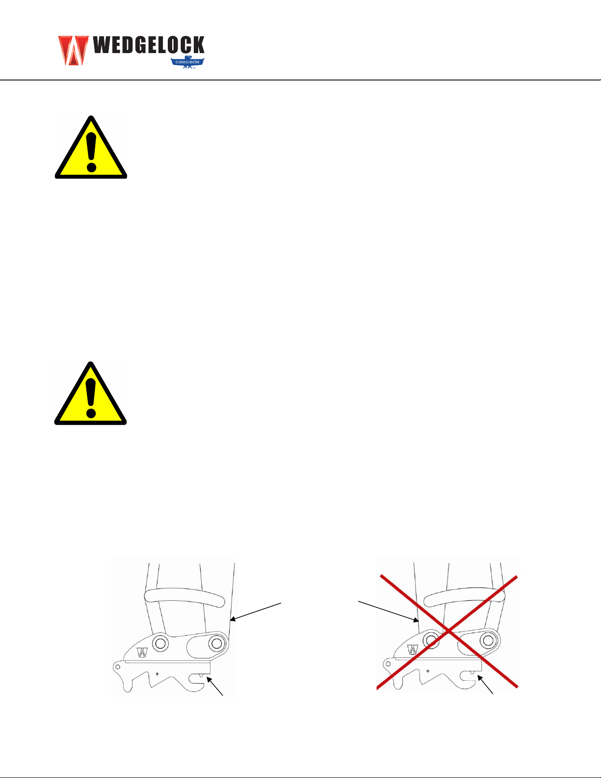
• Using the bucket curl cylinder lower the linkage into position
on the rear boss of the coupler (Fig 3.3.1).
• Align the coupler if necessary using a bar or lever.
• Insert the linkage pin through the coupler boss and linkage
boss.
• Alignpinretentionsystemandxlinkagepinintoplace.
• Locatetheo-ringsintothecorrectposition(iftted).
• NOTE – ORIGINAL OEM LINKAGE PIN MUST BE USED.
Page 7
SECTION 3: COUPLER INSTALLATION
3.2 REMOVE THE EXISTING BUCKET
• Before you fit the coupler to the carrier machine you have
to firstly remove any existing attachment from the dipper
arm. (Fig 3.2.1)
Place the bucket or attachment in a safe position on the
ground.
Undo the pin retention systems holding the dipper pin and
link pin in their position.
Gentle raise the bucket off the ground and crowd the
cylinder until the weight is off the dipper pin.
Remove the dipper pin and place in a clean area.
Lower the bucket to the ground with the crowd cylinder
until there is no longer weight on the link pin.
Remove the link pin and place in a clean place
Fig 3.2.1 Remove Bucket
3.3 FITTING THE COUPLER (Link Pin)
• Ensure the coupler is sitting on a flat surface in the correct
orientation.
Align the dipper arm of the carrier machine with the
coupler.
Position the o’rings for the linkage boss assembly on the
linkage boss (if fitted).
Using the crowd cylinder lower the linkage into position on
the rear boss of the coupler (Fig 3.3.1)
Align the coupler if necessary using a bar or lever.
Insert the linkage pin through the coupler boss and
linkage boss.
Align pin retention system and fix linkage pin into place.
Locate the o’rings into the correct position (if fitted).
NOTE – ORIGINAL OEM LINKAGE PIN MUST BE
USED.
Fig 3.3.1 Lower linkage into coupler
NORTH AMERICA

9
NORTH AMERICA
SECTION 3: COUPLER INSTALLATION
3.4 FITTING THE COUPLER (Dipper Pin)
• Placeo-ringsoverearplatesofcouplertoholdinpositionuntilreadyfornalplacement.
• Carefully raise the dipper arm of the carrier machine so that the weight of the coupler is off the
ground. Ensure that the dipper arm is in a vertical position. (Fig 3.4.1).
• Retract the bucket curl cylinder until the coupler front boss aligns with the dipper pin hole. The
coupler will balance allowing an easy insertion of the main dipper pin.
• Alignpinretentionsystemandxdipperpinintoplace.
• Grease both the dipper pin and the linkage pin.
• Rotate coupler through full rotation to check clearances.
• NOTE – ORIGINAL OEM DIPPER PIN MUST BE USED.
Fig 3.4.1 Raise dipper arm to
take weight off coupler
Fig 3.4.2 Retract bucket curl cylinder
to align dipper pin
CAREFULLY ROTATE THE COUPLER THROUGH FULL ROTATION TO
CHECK CLEARANCES
IF THERE ARE ANY SIGNS OF INTERFERENCE STOP IMMEDIATELY AND
CONTACT YOUR WEDGELOCK DEALER
Page 8
SECTION 3: COUPLER INSTALLATION
3.4 FITTING THE COUPLER (Dipper Pin)
Place o’rings over ear plates of coupler to hold in position until ready for final placement.
Carefully raise the dipper arm of the carrier machine so that the weight of the coupler is off the
ground. Ensure that the dipper arm is in a vertical position. (Fig 3.4.1).
Retract the crowd cylinder until the coupler front boss aligns with the dipper pin hole. The coupler
will balance allowing an easy insertion of the main dipper pin.
Align pin retention system and fix dipper pin into place.
Grease both the dipper pin and the linkage pin.
Crowd coupler through full rotation to check clearances.
NOTE – ORIGINAL OEM DIPPER PIN MUST BE USED.
Fig 3.4.1 Raise dipper arm to
take weight off coupler
Fig 3.4.2 Retract crowd cylinder
to align dipper pin
CAREFULLY CROWD THE COUPLER THROUGH FULL ROTATION TO CHECK
CLEARANCES
IF THERE ARE ANY SIGNS OF INTERFERENCE STOP IMMEDIATELY AND
CONTACT YOUR WEDGELOCK DEALER
NORTH AMERICA

10
NORTH AMERICA
SECTION 4: HYDRAULIC KIT INSTALLATION
There are three main sections to the hydraulic kit installation which consists of:
• Fitting of the Hose Clamp Bracket to the dipper arm.
• Fitting of the I-Lock Control Valve in the engine/pump compartment.
• Routing the 3 Line Hydraulic Circuit to complete the hydraulic part of the coupler installation.
4.0 HOSE CLAMP BRACKET
The Hose Clamp Bracket is a square steel plate with 2 holes drilled and
tapped for attaching the hose clamps to it. Note correct orientation. (Fig
4.0.1)
• Positioning of the Hose Clamp Bracket and the hose routing is
criticaltothelifecycleofthejumperhoses.(Fig4.0.2)
• To determine the optimum position of the hose clamp bracket
rstrotatethebucketcurlcylinderthroughfullrotationtocheck
available clearances for the bracket at both full stroke and zero
stroke.
• The hose clamp bracket should be placed as close as possible to the
main dipper pin to minimize hose length.
4.1 FITTING THE HOSE CLAMP BRACKET
• Once the optimum position has been determined, clean and prepare the surface of the dipper
arm to be welded.
• Lightly tack the hose clamp bracket into position, carefully tacking only the ends of the bracket.
(Refer to welding precautions and carrier machine service manual for welding instructions).
• Fit all 3 (Blue) hoses to the Coupler and Safety cylinders. (This may require removing the coupler
cylindertoaccessthettings)Coverthehoseswiththenylonabrasivesleeveprovidedand
route the 3 hoses together through the Hose Clamps and attach to the bracket.
• Rotate coupler SLOWLY through full rotation checking that
the hoses can move freely and are not subject to pinching
or crushing at any point. Re-position hose clamp bracket if
required.
• Remove hoses, stitch weld the sides ONLY of the hose clamp
bracket to the dipper arm. (Fig 4.1.1 Stitch weld location)
• Touch up paint nish on welded component to match carrier
machine color.
Fig 4.0.2
Fig 4.0.1 Hose Clamps and Bracket
weld bracket
to boom
weld bracket
to boom
Fig 4.1.1

11
NORTH AMERICA
SECTION 4: HYDRAULIC KIT INSTALLATION
Fig 4.3.1 Mounting Plate
4.2 THE I-LOCK CONTROL VALVE
The I-Lock Coupler is designed to operate on the carrier machine’s MAINS PRESSURE
supply.TheI-LockControlValvecontrolstheoilpressureandoilowtothecoupler
for both the Primary Wedge function AND the Safety Knuckle function. The I-Lock
Coupler Control Valve MUST BE USED for any installation of an I-Lock Coupler.
• The I-Lock Control Valve consists of twin solenoid valves, one pressure reducing
valve and 5 ports for hose routing. The distinguishable markings are there to assist with the
electrical connection and hose routing to ensure that the coupler operates in accordance with
which it has been designed. (Fig 4.2.1)
• The markings on the control valve are as follows.
Twin Solenoid Valves
• SAFETY – safety knuckle solenoid.
• WEDGE – primary wedge solenoid.
One Pressure Reducing Valve
• 1. PRV set to 145 Bar
5 Ports for hose routing
• P – pressure in.
• T – tank return.
• RET – primary wedge retract.
• EXT–primarywedgeextend.
• SAFETY – safety knuckle release.
• For pressure settings refer to the pressure settings chart on page 20.
• For service details regarding the control valve refer to the service section in the Operators
Manual.
4.3 INSTALLING THE CONTROL VALVE
• IdentifythepumpthatdeliversowtotheBUCKETCURLCYLINDERofthecarriermachine.
This is the most common pump used for hydraulic couplers operating on
mains pressure (refer to the carrier machine service manual if required).
• Utilizing the mounting plate supplied determine a suitable location in the
pump / engine compartment of the carrier machine to mount the control
valve. The mounting plate can either be welded or bolted into position. (Fig
4.3.1 Mounting Plate)
• Bolt the Control Valve to the mounting plate with the bolts provided.
NOTE: The best position for mounting of the control valve may be determined after the hose routing
fromtheboomtothepumpcompartment.Checkwherethehosesexitfromtheboomendinthe
pump compartment before mounting the valve as the I-Lock hoses will invariable follow this same
route.
Fig 4.2.1 I-Lock Control Valve
Twin Solenoids
PRV set to 145 Bar
P
Check Valve

12
NORTH AMERICA
SECTION 4: HYDRAULIC KIT INSTALLATION
4.4 HOSE ROUTING
Wedgelock Hose Kits have been designed to improve the speed and ease in which an installer
cantthehydraulickit.Thecontentofthehydraulichosekithasbeenpredeterminedtoensure
that,inmostcases,themajorityofttingsrequiredtocompletetheinstallareprovided.Insome
circumstancesadditionalttingsmayhavetobesourcedtocompletetheconnectiontothepump
test port and tank return. For information regarding the port type at these locations please refer to
the carrier machine service manual.
The “Pre-Crimped” Wedgelock hose kits are color coded at each end of the pre-crimped hoses.
Following the Installation Reference Card will assist with identifying each of the hoses to be routed
in respect to their relative positions on the carrier machine. Once the Hose Clamp Bracket and
solenoid control valve are in position begin routing the hoses from the coupler end of the machine
to the engine compartment end.
If using a “Pre-Crimped” Hose Kit follow the instructions ensuring that each color coded hose is
positioned as required. If using a ‘Lose Fitting Kit” you can use the color coded instructions as a
guide to achieve the same results.
4.5 HOSE ROUTING – DIPPER ARM
• Connect the “Dipper Arm” hoses to the coupler cylinder and the safety latch cylinder. These
hoses will be color coded BLUE. Route these hoses through the Hose Clamp Bracket and up
along the upper side of the of the dipper arm.
• Determine best position for the hose clamps provided. Prepare surface of the dipper arm for
welding the clamps into position. Weld clamp assemblies (if needed) ensuring that only the
vertical ends of the clamp brackets are welded. Touch up paint the dipper arm and clamp to
match the carrier machine color.
• During clamp welding procedure ensure that the dipper hoses are placed in a clean and safe
position away from heat and the welding area.
• Lightly clamp dipper arm hoses into position, do not fully tighten at this stage. (Fig 4.5.2)
Fig 4.5.2 Hose Clamp Assembly

13
NORTH AMERICA
SECTION 4: HYDRAULIC KIT INSTALLATION
4.6 HOSE ROUTING – BOOM
• Fit the nylon abrasive sleeve over the loose ends of the Dipper hoses.
Using the GREEN color coded hoses for the Boom, connect these to the
dipper arm hoses. (Fig 4.6.1)
• Lay the Boom hoses along the top of the boom arm in preparation of
determining the best hose clamp position for this part of the installation.
(Fig 4.6.2)
• Mark the position of the top hose clamp on the boom, allowing for the hose to follow the boom
movementrelativetothedipperarmmovementonthetoppivotpoint.Followingtheexisting
hose route and length through this pivot area is recommended.
• Mark the position of additional hose clamps along the top of the boom. With some kits hose
clamps are only provided for the Dipper. Use the Zip-Ties provided for securing the coupler
hoses to the boom. Prepare the surface of the boom for welding in these locations. Weld clamp
assemblies ensuring that only the vertical ends of the clamp brackets are welded. Touch up
paint the boom and clamp to match the carrier machine color.
• Tightenallhosejointsbetweenthecouplercylinderandthedipperarmtoboomconnections.
• Tightentheclampassemblies,pullingthroughanyexcesshose,workingfromthedipperend
to the bottom of the boom. Allow “hose slack” for pivot movement and ensuring that the hose
Dipper to Boom Hose Joint
Clamp Assemblies
(Multiple locations along boom)
Boom to
Valve Hose
Joint
Hose slack for
pivot movement
(with nylon abrasive sleeve)
Fig 4.6.1 Hose Joint
(Typical)
Hose slack for pivot movement
(with nylon abrasive sleeve)
Clamp Assemblies
(Multiple locations along boom)
Fig 4.6.2 Boom Hose Routing
Dipper to Boom Hose Joint
Boom to Valve Hose Joint

14
NORTH AMERICA
SECTION 4: HYDRAULIC KIT INSTALLATION
4.7 HOSE ROUTING – BOOM TO VALVE
• Connect the RED color coded hoses for the Boom to Valve to the boom hoses at the base end
of the boom.
• Route the hoses through to the pump compartment towards the control valve following the
existinghoseroutingfromtheboomend.
• Trace the hoses from the quick coupler cylinder right through to the end where they connect to
the valve to determine the correct hose for each port position on the valve.
• Connect the hose ends to the control valve ensuring that they are connected to their respective
port positions relative to the cylinder.
• CabletieBoomtoValvehosestoexistinghoseswhereappropriateandcoilanyexcesshosein
the pump compartment. Ensure that the hoses are not bound up or under any strain.
• Tightenallhosejointsandttingsbetweenthelowerboomendandthecontrolvalve.
4.8 HOSE ROUTING – VALVE TO PUMP / TANK
• Using the BLACK color coded hoses from the install kit connect the hose ends to the valve
marked P (Pump) and T (Tank).
• The supplied Check Valve should be connected directly to the “P” (Pressure) port on the I-Lock
ControlValvewiththettingsprovidedinthekit.(SeeControlValveAssyFig4.2.1)
• Utilizing a “TEST PORT” on the pump that delivers hydraulic pressure to the bucket curl cylinder
circuit (see section 4.3) connect the hose from the check valve on the “P” port to the test port.
• Locateanexistingtanklinehoseonthemainreturnmanifoldorhydraulictank.Disconnectthe
existinghoseandinstallateetting.
• Reinstalltheexistinghoseontooneendoftheteeandthenconnectthenewtanklinehosefrom
the control valve “T” port to the other end of the tee.
• Cabletiehosestoexistinghoseswhereappropriateandcoilanyexcesshoseifrequired.Ensure
that the hoses are not bound up or under any strain.
• Tightenallhosejointsandttingsbetweenthecontrolvalveandthepumpandtank.
NOTE 1: When utilizing a “Pre-Crimped” or “Loose” hose kit supplied by Wedgelock we have
endeavoredtosupplythemajorityofthettingsrequiredtocarryoutacompleteinstallofanI-Lock
Coupler,howeverduetothevastarrayofdifferentcarriermachines,ttingtypesandportsizes,not
allcircumstancesmaybeaccountedfor.Ininstanceswherethettingssupplieddonotmatchthe
port size or the type of carrier machine that this install is being carried out on please contact your
nearestmachinerydealerorhydraulicttingsproviderfortheadditionalappropriatecomponent(s).
NOTE 2: See Hydraulic Schematic (Fig 6.0.1)

15
NORTH AMERICA
SECTION 5: ELECTRICAL INSTALLATION
Fig 5.0.3 Solenoid Loom
Fig 5.0.1 Dual Switch Assembly
Fig 5.0.2 I-Lock Controller
The I-Lock Controller, Dual Switch Assembly and Solenoid Loom are designed to enable a “plug &
play” electrical installation process.
• Determine a suitable position for the I-Lock Controller. Ensure the position is a dry location and
easilyaccessible.Mountintoposition.(Caution-Donotovertightenxingscrews)
• Find two spare locations in the machine console, preferably side by side, to insert the dual
rocker switches.
• RoutetheswitchwirestotheI-LockController.Connectthecorrespondingmalespadettingto
the female connector on each of the assemblies.
• Locate a switched (fused) power source from within the console of the carrier machine. Connect
the RED power lead on the Dual Switch Assembly to the power source.
• Find a suitable earth location (negative) and connect the BLACK wire from the I-Lock Controller.
• Plug the Solenoid Loom into the I-Lock Controller.
• Route the Solenoid Loom from the I-Lock Controller position through to the engine compartment
where the I-Lock Solenoid Valve is located.
• Connect the RED labeled DIN Plug to the “WEDGE” solenoid.
• Connect the BLACK labeled DIN Plug to the “SAFETY” solenoid.
• Ensurethatallelectricalloomsareroutedandxedsecurelyusingcabletieswhererequired.
• NOTE: See Electrical Assembly (Fig 6.2.2)
5.0 ELECTRICAL INSTALLATION
The I-Lock Coupler must be operated utilizing the I-LOCK CONTROLLER, DUAL SWITCH
ASSEMBLY and SOLENOID LOOM. The proprietary electrical components have been
designedinconjunctionwiththefunctionalityandoperationofthecouplersafetyfeatures.
The built in “Timer” and “Operational Sequences” controlling the solenoid valves are
features which provide the operator and fellow co-workers a safe work environment during
attachment change over.
Failure to utilize the proprietary electrical components with the I-Lock Coupler could result in coupler
malfunction, causing serious harm or even death. (Fig 5.0.1 & 5.0.2 & 5.0.3)

16
NORTH AMERICA
SECTION 6: ASSEMBLIES
6.0 LOOSE HOSE KIT ASSEMBLY
6.1 PRE-CRIMPED HOSE KIT ASSEMBLY
Fig 6.0.1 Loose Hose Kit Assembly
Fig 6.1.1 Pre-crimped Hose Kit Assembly
HYDRAULIC
COUPLER & I-LOCK
SAFETY SYSTEM
Pump & Tank Hoses
Dipper Arm Hoses
Boom Hoses
Coupler Hoses
MACHINE
SPECIFIC
SETTINGS
CHECK
VALVE
I-LOCK SAFETY
SYSTEM & COUPLER
CONTROL VALVE
12V OR 24V
HYDRAULIC
COUPLER & I-LOCK
SAFETY SYSTEM
MACHINE
SPECIFIC
SETTINGS
CHECK
VALVE
I-LOCK COUPLER
CONTROL VALVE
Pump & Tank Hoses
Dipper Arm Hoses
Boom Hoses
Coupler Hoses

17
NORTH AMERICA
Fig 6.2.2 Electrical Assembly
6.2 ELECTRICAL ASSEMBLY
SECTION 6: ASSEMBLIES
I-Lock Controller
Male / Female
Connectors
Solenoid Loom
Earth Connection
Din Plugs

18
NORTH AMERICA
SECTION 7: FINISH & TEST
7.0 FINISH & TEST
Before starting this section, position the machine in the “Oil Level Check” position as
suggestedbytheexcavatormachinemanufacturer.Checktheoillevelsightgauge
on the hydraulic tank. Add hydraulic oil if necessary (refer to the carrier machine
service manual for further information).
• Check the hose clamp assemblies and valve mounting bolts are tightened as
per the Torque Setting of Metric Bolts & Nuts Chart (Fig 9.0.1)
• Starting at the coupler end thoroughly check that the hose connections are tightened through
out the complete circuit as per the JIC (SAE 37º FLARE) Connection Chart (Fig 9.1.1).
• Clear all personnel and all obstacles from the swing radius area and working parameter of the
machine.
• From the seat of the excavator, start the machine and lower the excavator arm to near the
ground.Inaveryslowmotion,usingtheexcavatorlevers,raisethedipperarmandrotatethe
couplerthroughfullrotation.Thenraisetheboomoftheexcavatorandmotionthedipperarm
cylinder to full extension. Now motion the dipper arm cylinder to full retraction, lowering the
boom arm in unison. Use this process to check the hose routing throughout the complete circuit.
Ensure that the hoses are not under any strain or subject to potential jamming or pinching.
Assistance will be required to do this. Modify hose routing if required.
• Running the machine at idle or a low engine RPM setting to supply a low volume of oil through
the circuit. Activate the circuit and check for any leaks. Shut down the machine immediately if
leaks are detected, then tighten coupler as required and re-check.
• Activate the circuit several times to ensure that the system is working correctly – refer to the
I-Lock Coupler Operators Manual.
• Once the test procedure has been completed, touch up paint any welded brackets or assemblies
and cable tie any loose hoses.
• Afx“InCab”Decalsinasuitablelocationwithintheoperatorsworkingarea.(Seesection8.0
In Cab Decals)
Before using the I-Lock Coupler carefully read the
I-Lock Coupler Operators Manual thoroughly.

19
NORTH AMERICA
8.0 IN CAB DECALS
Thefollowingtwo“InCab”Decalsmustbeafxedinasuitablelocationwithintheoperatorsworking
area. For replacement decals please call your nearest Wedgelock dealer. (Fig 8.0.1 Warning Decal &
8.0.2 I-Lock Coupler Oerating Decal)
Fig 8.0.1 Warning Decal
Fig 8.0.2 I-Lock Coupler Operation Decal
SECTION 8: IN CAB DECALS

20
NORTH AMERICA
SECTION 9: TORQUE CHARTS
9.0 TORQUE CHART – METRIC BOLTS
The following chart gives the standard torque setting of the bolts used in this hydraulic kit installation.
It is important to follow the chart when installing bolts and nuts. Failure to do so could result in
prematurefailure,damagetocomponents,orevenseriousinjury.(Fig8.0.1)
Fig 9.0.1 Torque Setting of Metric Grade 8.8 Bolts & Nuts
9.1 TORQUE CHART – JIC CONNECTIONS
JIC(SAE37ºFlare)Connectionsareaverycommonconnectioninuidpowerapplications.Both
themaleandfemalettingshavea37ºseat.Thesealtakesplacebetweenthemaleareandthe
female cone seat. The thread holds the connection mechanically.
Fig 9.1.1 JIC Connections Chart
Torque Setting of Metric Grade 8.8 Bolts & Nuts
Bolt Dia x Pitch (mm) Nm Lb.Ft
M6x1.0 9.9 7.3
M8x1.25 24.0 17.7
M10x1.5 48.0 35.4
M12x1.75 83.0 61.2
M14x2.0 132.0 97.3
M16x2.0 200.0 147.4
M18x2.5 275.00 202.7
M20x2.5 390.0 287.4
Note: 1Nm = 0.102kgm = 0.737 lb.ft
Torque Setting of JIC Connectors
Nominal Size Dash Size Nm Lb.Ft F.F. F. T.
1/4” -4 15 - 17 10.8 - 12.5 2
3/8” -6 27 - 30 19.6 - 22.0 1 1/4
1/2” -8 59 - 65 45.5 - 47.8 1
9.2 PRESSURE SETTING CHART
The following chart shows the range of allowable pressure settings for the I-Lock Coupler circuit.
It is highly recommended that the pressures for each function are tested and checked
before the equipment is put to use.
I-Lock Control Valve
Marking Function Pressure Range (bar) Pressure Range (psi)
P Pressure In Full Mains
T Tank return N/A
RET Retract Primary Wedge FullMains(260barmax) Fullmains3750psimax
EXT ExtendPrimaryWedge 138-145 2000-2100
SAFETY Safety Knuckle Release FullMains(260barmax) Fullmains3750psimax
I-Lock Primary Cylinder
Marking Function Pressure Range (bar) Pressure Range (psi)
RET Retract Primary Wedge FullMains(260barmax) Fullmains3750psimax
EXT ExtendPrimaryWedge 138-145 2000-2100
SAFETY Safety Knuckle Release FullMains(260barmax) Fullmains3750psimax
Table of contents
Other WEDGELOCK Industrial Equipment manuals