WEDICO MAN C User manual

57-e.DOC / K-MAN 29.01.2004 Page 1
qÉÅÜåáÅ~ä=Ç~í~W=
Truck tractor:
Length..................................................450 mm
Width....................................................175 mm
Height...................................................265 mm
Track (tread) front.................................140 mm
Track (tread) rear..................................116 mm
Weight with motor drive and NiCads........3.5 kg
Superstructure:
Components of die cast aluminium
and aluminium sheet,
stainless steel threaded connectors and
bending wire components,
high impact plastic components.
Cab tiltable.
Model is prepared for RC-installation.
We are glad that you have decided on one of the precious WEDICO
truck models! For the manufacture of individual parts WEDICO uses
durable materials of high quality - rarely to find in these days. This
guarantees durability and enjoyment of your model for years to come.
If you should ever require replacement parts, please get in touch
with your dealer or directly with WEDICO. For order purpose it is im-
portant using not only those EDP-numbers mentioned within the gen-
eral parts list (see last page of this instruction) but also indicating the
necessary details concerning colour, quantity and exact term of the
spares required. You may be assured that WEDICO will supply the re-
placement part as quick as possible.
®WEDICO
Technical data
Drive Motor: WEDICO-
Bühler electric motor, rated voltage
12 volts, 7-
segment collector. Idling speed 6000 rpm.
Torque 5 Ncm (approx. 500 pcm) at 4000 rpm.
Power drawn under load at max. torque approx. 3 A.
Idling power consumption with connected gearing
and one differential approx. 0.5 A.
Gearbox Standard single speed 2-
stage spur gearbox with
self-lubricating gearwheels. Reinforced housing.
Gear ratio 5.6 : 1.
Power
transmission
Stainless steel drive shafts with ball joints between
gearbox and differential. Differential gear.
Gear ratio 2 : 1.
Superstructure
Frame made of aluminium section, 2 mm thick; to
r-
sion resistant.
Rear bumper made of section 2 mm thick.
3-part (rear) to 4-
part (front) stainless steel leaf
spring packages on all axles.
Soft rubber tires with reproduction of original tread
pattern.
Fastening components made of stainless steel. All
body parts are made from aluminium sheet an
d
aluminium die cast 1.5 to 2 mm thick.
Finish
Extremely hard epoxy powder coating. Excellent
base when repainting for special purposes.
Assembly During assembly it is advisable following the s
e-
quence given by these instructions. Observe the
notes expl
aining the various steps in assembly and
use only those parts which are provided; this will
insure a correct result of assembly.
WEDICO system kits are known for their exact fit.
© 2000 by WEDICO, P.O. Box 20 04 18, D - 42 204 Wuppertal, Germany.
We can assume no liability for technical or typographical errors.
We reserve the right to incorporate technical modifications.
Duplication and reproduction only with our express consent.
Art.-No. 57 white
Art.-No. 58 red
Art.-No. 59 black
`çãéäÉíÉ=háí==j^k
=
aêáîáåÖ=ãçÇÉä==`=
B-57-0

`çãéäÉíÉ=háí==j^k=
`çãéäÉíáçå=çÑ=~ëëÉãÄäó=Öêçìéë
613
607
633
615
611
610
609
616
397
115
632
10
632 1
10
612
397 623 13 10
622
13 10 56
617
618
600
608
609
498
614
470
NÉåÉê~ä=
1.1 The assembly instruction
On the left side you find the illustrations of the assembly groups in-
cluding the part lists indicating the necessary components. On the
right side, marked by the corresponding number of illustration, the in-
structions for the proper assembly.
1.2 Screws and other small parts
M3 nuts are generally not provided with an identification number. As
a help easier to find out screws and small parts, please see ill. 1
which is showing you the most important components at original size.
1.3 Cutting threads
Threads have to be cut into eleven of the screw holes on the front
panel (see ill. 2 on the right-hand top side), as well as into the four
lateral screw holes on the underside of the roof, and into both screw
holes on the side panels. Before you start the proper assembly, use
those two self-tapping screws 111 supplied with this kit to cut these
threads. You should lubricate the screw and the screw holes (using a
little petroleum jelly, for instance) before doing so and afterwards use
a soft cloth to remove excess lubricant.
O^ëëÉãÄäó=Öêçìé=çÑ=íÜÉ=Ñêçåí=ëÉÅíáçå=
2.1 Assembly of the doors
Into the inner cover of the left door lay one door lock 610 and two
door hinges 615. Press the mirror support 470, the door shield 613 as
well as the door lock bushing 614 into the corresponding openings of
the left door 607. Then insert the door handle 611 from inside into
the corresponding opening of the door and screw up the inner door
cover with the proper door using two screws 397 and one screw 115.
From the enclosed plastic tube cut off a piece of 27mm length. The
bushing you have thereby made is indicated in the illustration by 633.
From underneath press then the pin for door hinge 616 into the
proper door hinge. First slide the bushing 633 and afterwards one of
the door hinge bushings 612 between both door hinges onto the door
hinge pin and press now the door hinge pin into the upper door
hinge. Slide now the second door hinge bushing 612 onto the bottom
part of the hinge pin.
Prepare now the right door 608 by the same way.
2.2 Assembling radiator, front panel, steering wheel, doors
Use two screws 397 to fix the radiator grille 617 as well as the grille
frame 618 onto the front panel 600 and press the front screen 623
into the front panel. For this purpose lay the screen into the opening
on the left inner side of the front panel and bend it on its centre point
backwards until the screen may laid as well into the right side. Press
then the screen frontwards onto the front panel. The screen should
now be fixed.
With screw 1add now the dashboard switch 498 as well as the steer-
ing wheel 56 onto the dashboard 622. Slide the door hinge pins with
the pre-mounted doors into the bushings lateral of the dashboard.
With screws 10 and washers 13 fix then the proper dashboard with
the doors onto the front panel. Screw the door hinge pins with the at-
tached bushings 612, with hinge supports 632 and screws 10 onto
the front panel. Adjust the doors until they lay - when closed - in
parallel to the front panel and to the roof. For this purpose lightly
bend the aluminium door hinges as follows: squeeze the upper
hinges a bit together, and push a bit the bottom hinges apart.
57-e.DOC / K-MAN Page 2
Assembly group of the front section ill. 2
Screws and other small parts at 1:1 ill. 1
Tapping screw 2.2 x 6.5
Part no. 397
Tapping screw 2.2 x 4.5
Part no. 21
Countersunk tapping screw 2.2 x 4.5
Part no. 564
Nut M4
Part no. 19
Nut M3
---
Nut M2
Part no. 109
Square nut M3
Part no. 12
Knurled nut M5
Part no. 210
M3 x 8
Part no. 2
M3 x 6
Part no. 1
Self-cutting screw M3 x 8
Part no. 111
Self-cutting screw M3 x 6
Part no. 10
M2 x 8
Part no. 115
M2 x 6
Part no. 114
Stud bolt M3 x 18
Part no. 16
M4 x 25
Part no. 18
M4 x 8
Part no. 17
M3 x 25
Part no. 6
M3 x 20
Part no. 5
M3 x 16
Part no. 4
M3 x 12
Part no. 3
M3 x 10
Part no. 57
Shim 5 x 10 x 1
Part no. 391
Washer 4.3
Part no. 20
Washer 3.2
Part no. 13
Washer 2.2
Part no. 24
Spring washer 3.2
Part no. 14
Serrated washer 3.2
Part no. 15
Retaining washer 3.2
Part no. 25
B-57-1
B-57-8
Qty.
No. Assembly part
2 611
Door handle, MAN
4 612
Hinge bushing, door
2 613
Door shield, MAN
2 614
Door lock bushing
4 615
Door hinge, MAN
2 616
Pin for door hinge
∅1.5 x 43.5
1 617
Radiator grille, MAN
1 618
Frame radiator grille
1 622
Dashboard MAN
1 623
Windscreen MAN
4 632
Hinge support
2 633
Bushing 27mm
(to be cut off the
plastic tube 70mm)
Qty.
No. Assembly part
1 1
Screw M3 x 6
6 10
Self-cutting screw M3 x 6
2 13
Washer 3.2
1 56
Steering wheel
2 111
Self-cutting screw M3 x 8
(for threading)
2 115
Screw M2 x 8
6 397
Tapping screw 2.2 x 6.5
2 470
Mirror hinge, bottom
1 498
Switch dashboard
1 600
Front panel MAN
1 607
Door -lh-, MAN
1 608
Door -rh-, MAN
2 609
Doorinner cover,MAN
2 610
Door lock, MAN

`çãéäÉíÉ=háí==j^k=
`çãéäÉíáçå=çÑ=~ëëÉãÄäó=Öêçìéë
707
13
26
19
706
15
15
707
13
26
568
655
19
19
713
1256
713
289
706
4
4
483
1257
26 16
13
26 16
13
12
96
383
93
372
383
96
12
95
P^ëëÉãÄäáåÖ=íÜÉ=êççÑ=ëÉÅíáçå=
3.1 Antenna socket and horns
Affix the components for the antenna socket 568 as shown in the il-
lustration. Please note that the antenna cable from the remote con-
trol receiver will have to be soldered to the antenna socket.
The horns 707 are fitted with bushings 26 and washers 13 and then
affixed, through the holes provided in the roof 1263, using screws 4,
nuts M3 and serrated washers 15.
3.2 Roof lamps
Install a bulb 713 in each of the roof lamps 706, threading the leads
through the lamp housings first. The cables are easier to thread if
you twist the two conductors together and bend the ends slightly.
Pointed tweezers can help in pulling the cable through. Do not pull
the bulbs too far into the lamp housings; the bulbs should protrude by
2 to 3 mm. After the roof lamp lenses 289 have been pressed onto
the lamp housings, the housings are inserted in the holes in the roof
and secured with nuts 19.
The bulb leads and the red/black cable from the switch panel are at-
tached to the terminal strip - see Section 23.3 and ill. 23. Use adhe-
sive pads 655 to affix the terminal strip under the roof so that the ca-
bles are not visible inside the cab.
QoÉ~ê=é~åÉä=ëÉÅíáçå=
4.1 Assembling the exhaust system
The illustration is showing the assembly of the left side only. Please
mount the right side in the same sense.
Slide one square nut 12 each into the depressions at the exhaust
caps 96. Now slide these caps into the muffler 93 so that the nut is
located behind the hole. Slide the exhaust tail pipe 95 from above
into the muffler cap until catching; clamp it in place with a stud 16.
Ensure that the tip of the exhaust pipe points is aligned with the nut.
Follow the same procedure for the exhaust manifold 483. Its lower
opening must also be aligned with the nut. Then a bushing 26 and
washer 13 are slid onto the two studs.
Now use the stud bolts to insert the exhaust system through the mat-
ing holes at the rear panel 1257, and afterwards secure it with the
M3 nuts. Press the fixing caps 383 from above and below onto the
muffler and slide the exhaust shield 372 over them.
57-e.DOC / K-MAN Page 3
Assembling the roof section ill. 3
Rear panel section ill. 4
B-57-2
For threading the bulb leads
see proper text
Please clip
off the
solder pins
Terminal strip
for roof lamps
Qty.
No. Assembly part
4 96
Exhaust cap
2 372
Exhaust shield, chromed
4 383
Fixing cap
2 483
Exhaust manifold
1 1257
Rear panel, Complete
Kit MAN “C”
Qty.
No. Assembly part
4 ---
Nut M3
4 12
Square nut M3
4 13
Washer 3.2
4 16
Stud bolt M3 x 18
4 26
Bushing 4 x 0.5 x 7
2 93
Muffler 80mm
2 95
Exhaust tail pipe
Qty.
No. Assembly part
1 655
Adhesive pad,
double-sided
5 706
Roof lamp, chromed
2 707
Horn
5 713
Bulb 3V
1 1256
Roof, Complete Kit
MAN “C”
1 ---
Terminal strip for roof
lamps, 6-pole
Qty.
No. Assembly part
2 ---
Nut M3
2 4
Screw M3 x 16
2 13
Washer 3.2
2 15
Serrated washer 3.2
5 19
Nut M4
2 26
Bushing 4 x 0.5 x 7
5 289
Lens for roof lamp,
orange
1 568
Antenna socket,
complete

`çãéäÉíÉ=háí==j^k=
`çãéäÉíáçå=çÑ=~ëëÉãÄäó=Öêçìéë
10
111
15
111
15
12
225
75
13
76
12
103
57
619
620
397
631
621
12
602
2
605
13
2
603
606 222
366
109
10
713
14
463 114
624
459
4
R`~Ä=ëÉÅíáçå=
5.1 Assembling the cab
Use screws 4to screw the premounted front section onto the roof.
Make sure that on both sides the roof sits absolutely close to the
front section!
With screws 114 and nuts 109 attach the footboards 463 onto the
fenders 605 and 606. Screw on the left fender 606 with screws 10
onto the left side panel 6115, and the right fender 606 onto the right
side panel 603. Side panels with the fenders are now screwed on
as follows: with screws 10 onto the roof, and with screws 2, washer
13 and square nuts 12 onto the front panel along those webs pre-
pared. Now check again the position of the doors and re-adjust them
if necessary.
Should you intend applying a decal it is advisable doing it right now.
5.2 Seat rear panel and battery plate
First pass the switch toggles at the switch panel through the holes
provided in the seat rear panel 222; secure from the front using
four knurled nuts 210 (see therefore illustration 12).
Accordingly to the illustration attach the switch sticker onto the seat
rear panel; the letters indicating the switches do now stand on their
heads. Please see ill. 13b for the assignment of the switches. Now
slide one each square nut 12 into the slits of the four fixing gaps of
the side panels. Then fix the seat rear panel from underneath onto
the side panels using screws 2. Hang both seats 103 onto the seat
rear panel.
Now start mounting the battery carrier plate 225. Turn a nut M3 onto
the door handle 75 and tighten it. Then set on one washer 13 and
one spring washer 14 and insert the handle through the hole pro-
vided for in the battery plate. From the rear slide the door lock 76
over it and screw on one square nut 12. Door handle and door lock
should be fixed that way that they stay right-angled towards. It is ad-
visable using pliers to hold the door lock while securing it with the nut
M3. Finally set the battery plate into place: on the left side panel of
the cab it has to catch the groove provided for, and on the right side
panel insert it underneath that plate with the half-round sparing. By
turning the handle the plate gets locked.
5.3 Assembling the bumper with the lighting
Press the blinker lenses 621 as well as the headlight lenses 624 -the
funnel-formed side showing outwards- into the corresponding open-
ings of the bumper 619. Press one each bulb 713 into the outer clips
for the blinkers, and into the socket 459 for the head lights. Press the
socket, together with the bulbs, from the rear into the recesses of the
reflectors. Glue both reflector foils 631 into the reflectors 620 and
screw then the reflectors onto the bumper using screws 397. With
screws 57 and nuts M3 attach the bumper onto the front panel. Use
caps 366 to cover the recesses in the bumper.
57-e.DOC / K-MAN Page 4
Cab section ill. 5
Premounted
roof section
Sticker for
switch
Premounted
front section
Qty.
No. Assembly part
2 366
Lens flat, black
2 397
Tapping screw 2.2 x 6.5
2 459
Rubber funnel for
reflector
4 463
Access, fender
1 602
Side panel -lh-, MAN
1 603
Side panel -rh-, MAN
1 605
Fender -lh-, MAN
1 606
Fender -rh-, MAN
1 619
Bumper MAN
2 620
Reflector MAN
2 621
Blinker lens MAN
2 624
Headlight lens, MAN
2 631
Reflector foil MAN
4 713
Bulb 3V
1 ---
Decal
1 ---
Sticker for switch
Qty.
No. Assembly part
4 ---
Nut M3
6 2
Screw M3 x 8
3 4
Screw M3 x 16
4 10
Self-cutting screw M3 x 6
7 12
Square nut M3
3 13
Washer 3.2
1 14
Spring washer 3.2
4 15
Serrated washer 3.2
2 57
Screw M3 x 10
1 75
Door handle
1 76
Door lock
2 103
Seat
4 109
Nut M2
4 111
Self-cutting screw M3 x 8
4 114
Screw M2 x 6
1 222
Seat rear panel
1 225
Battery carrier plate
B-57-3

`çãéäÉíÉ=háí==j^k=
`çãéäÉíáçå=çÑ=~ëëÉãÄäó=Öêçìéë
115
929
760
723
655
176
13
26
2
2
26
13
28
655
2
2
13
5
476
74
477
4
4
45
720
721
721
722
719
724
564
564
57-e.DOC / K-MAN Page 5
SmêÉîáÉï=çÑ=íÜÉ==
ÉäÉÅíêáÅ~ä=ëóëíÉã=áåëí~ää~íáçå=
The illustration at the left shows the locations of the PCBs and the
routing of the ribbon cable beneath the frame. The cable will have to
be installed underneath the frame before the electrical devices are
installed in their entirety. The cable should run between the frame
and the axles, the fifth-wheel shaft and the screws used to affix the
tank. If the cable were to be laid later it would be necessary to disas-
semble some components already installed.
The best course of action is to read all the information on the electri-
cal system in Chapter 13 before you begin assembling the compo-
nents on the frame. This will give you an idea of which components
will be connected by cable.
T`çãéçåÉåíë=~íí~ÅÜÉÇ=íç=íÜÉ==
Ñêçåí=Ñê~ãÉ=ëÉÅíáçå=
7.1 Fixing parts for the cab
Using each two nuts M3 to attach one screw 4, washer 13 and bush-
ing 26 onto the lower front holes on both sides of the frame. At a
later stage of assembly (after the completion of all assembly groups -
see Chapter 12 - the front panel of the cab will be set hereon.
Once you have cut off the lateral cover on the locking device 476 (for
this purpose use either pliers or scissors), tense both springs 176
between those spigots of the locking device therefore provided. Then
press the locking device into the base 477 and fix the screw 115 into
the bore on top of the locking device. Now hang in the spring 74 as
follows: on top behind the screw head, and at the bottom on the nose
of the base. Now add the base cab locking onto the frame 45 with
screws 2and nuts M3. After adding the cab to the frame the locking
device catches the gaps of the rear panel and thereby holds of it.
7.2 Mounting the servo unit
Accordingly to the drawing, use screws 5, washers 13 and nuts M3
to fix the bushings 28 onto the steering servo. Add now this complete
unit onto the servo supporting angle and fix it with screws 2. Use
screws 2and nuts M3 to attach the servo supporting angle under-
neath the frame.
7.3 Mounting the PCB support
Use two adhesive pads 655 to affix the PCB support 723 behind the
servo supporting angle under the frame.
7.4 Assembling the blinker switch
Slide two single-bent springs 721 into the corresponding holes and
slots in the base plate 720. Insert the double-bent spring 722 into the
two holes on the lever blinker switch 724 and then place the eye of
the lever over the boss on the base plate. The cover plate 719 is now
secured to the base plate with countersunk screws 564.
Attach the blinker switch with two adhesive pads 655 that way onto
the steering servo, that the clamp-type connector 929 lays closely on
the fore edge of the housing.
Components attached to the front frame section ill. 7
View from below showing the location of components mounted onto the frame ill. 9
Cut off
this part
Assembly of blinker switch
Ribbon cable
from the switch
Steering servo
(not incl.
in the kit)
fully assembled
blinker switch
Front PCB Steering servo Ribbon cable Tank Rear axle Rear PCB
Blinker switch Gear Speed controller Differential B-44-6
green
brown
white
B-44-7
Qty.
No. Assembly part
4 564
Countersunk tapping
screw 2.2 x 4.5
4 655
Adhesive pad,
double-sided
1 719
Cover for blinker switch
1 720
Base for blinker switch
2 721
Spring, single bent
1 722
Spring, double bent
1 723
PCB support, small
1 724
Lever for blinker switch
1 760
Servo angle 1, small
1 929
Clamp-type connector,
3-pole
Qty.
No. Assembly part
12 ---
Nut M3
6 2
Screw M3 x 8
2 4
Screw M3 x 16
2 5
Screw M3 x 20
8 13
Washer 3.2
2 26
Bushing 4 x 0.5 x 7
2 28
Threaded bushing 20mm
1 45
Frame 3-axle chassis,
432mm
1 74
Draw spring
1 115
Screw M2 x 8
2 176
Coil spring for lever
1 476
Cab locking device
1 477
Base for locking device
Moment of torsion
of the servo should
be at 30 Ncm. The servo supporting angle
will fit servos with the following data:
L x W x H:........................41 x 20 x 38 mm
Gauge for screwing....................48 ±2 mm

`çãéäÉíÉ=háí==j^k=
`çãéäÉíáçå=çÑ=~ëëÉãÄäó=Öêçìéë
109
26
13
13
3
26
13
3
13
33
32
5
36
30
30
29
53
53
52
27
20
18
5
20
2
19
19
55
36
29
2
20
52
27 20 18
33
32
3
13
26
13
13
2613 3
30
789
1390
13
13
908
908
34
34
41
42
4
41
41
41
42
4
72
71
1
21
57
57
723
655
655
710
709
2
1
25
73
25
709
342
342
341
44 74
46
341
47
57-e.DOC / K-MAN Page 6
Front axle section ill. 9
Components attached to the rear frame section ill. 8
U`çãéçåÉåíë=~íí~ÅÜÉÇ=íç=íÜÉ==
êÉ~ê=Ñê~ãÉ=ëÉÅíáçå=
8.1 Mounting the fifth-wheel components
Attach the spring 74 to the link lever 44 with a screw 1and M3 nut.
Insert the bar 72 into the opening from above, securing it from below
with the link lever and a tapping screw 21. Mount the fifth-wheel 71
from above, inserting the feet into the slots in the frame. Slide the
shaft 73 through the holes at the side of the frame and the feet of the
fifth-wheel, catching the free end of the spring 74 between the feet
when doing so. The shaft is secured with two retaining washers 25.
Please ensure when attaching the fifth-wheel that the ribbon cable
with the two circuit boards is located between the frame and the
shaft (ill. 6).
8.2 Mounting the rear bumper assembly
First insert the bulbs 713 in the lamp caps 709 as shown in the figure.
Now affix the assembled caps to the rear bumper 47 using one each
screw 57 and M3 nut. From the rear insert the lenses into the bumper:
outwards the blinker lenses 341, inwards the rear light lenses 342.
Attach the frame tail piece 46 underneath the frame using screws 1
and M3 nuts. Then the bumper and carrier plate 710 are set in front
of the frame tail piece and attached with screws 2and M3 nuts.
Take particular care that the bulb cables are not clamped between
the bumper and the frame tail piece; this could cause a short cir-
cuit!
Using two adhesive pads 655, affix the PCB support 723 on the front
surface of the carrier plate, centred and flush with the bottom edge.
Vcêçåí=~ñäÉ=ëÉÅíáçå=
9.1 Mounting the suspension with front axle
First install the screws 3together with washers 13, bushings 26, and
M3 nuts at the rearward holes in the frame, provided for attaching the
springs. Then attach the open ends of the two long spring leaves 32
at the bushings and use an identical set of parts to screw the closed
ends to the front of the frame 45. One nut 19 each is pressed into the
hexagonal depressions at the steering lever 42. Use two screws 5
and M3 nuts to attach to the long spring leafs, previously mounted,
two medium spring leaves 33 and a short spring leaf 34 along with
two half-axle guards 41, into which the front axle 55 and steering
lever 42 have been inserted. Before tightening down the screws 5
ensure that the spring sets are not under tension and can move
freely.
11.2 Mounting the wheels and steering linkage
First mount the standard tyres 53 on the rims 52. Then use screws
18 and one washer 20 each in front of and behind the axle tube 27
located in the hub to bolt the wheels to the steering lever, using the
nut already inserted. To the outer holes on the steering levers fix two
screws 4along with nuts M3. To this unit add now the track rod 1390
using washers 13 and stop nuts 908; do not tighten the stop nuts but
leave the track rod moveable.
With screws 2fix two ball bolts 29 to the inner holes on the steering
levers for the attachment of the steering rods. To a steering rod 36
add one nut 109, fork head 789 and ball socket 30. The steering rod
has to be bent slightly, depending on the size of the servo unit. After-
wards clip this steering rod for the servo linking to the left-hand ball
bolt. For operation of the blinker switch, add to the right-hand ball
bolt another steering rod 36, equipped with two ball sockets 30. Ad-
just the distance between the ball sockets so that the wheels are in
the straight-ahead position when the lever of the blinker switch is in
its neutral setting.
Note!
The kit contains two
additional red lenses 342
for the US chassis version
equipped with red blinkers.
Frame
B-44-9
B-44-9
For a better overview the
illustration is showing
an assembly without the
parts attached to the front
frame section
Qty.
No. Assembly part
1 73
Shaft for fifthwheel
1 74
Draw spring
2 341
Blinker lens high, orange
4 342
Lens/rear light high, red
2 655
Adhesive pad,
double-sided
2 709
Lamp cap
1 710
Carrier plate for
support PCB
6 713
Bulb 3V
1 723
PCB support, small
Qty.
No. Assembly part
7 ---
Nut M3
3 1
Screw M3 x 6
2 2
Screw M3 x 8
1 21
Tapping screw 2.2 x 4.5
2 25
Retaining washer 3.2
1 44
Link lever
1 46
Frame tail piece
1 47
Bumper, rear
2 57
Screw M3 x 10
1 71
Standard fifthwheel
1 72
Bar for kingpin
Qty.
No. Assembly part
2 32
Spring long, “AF“
4 33
Spring medium, “AF“
2 34
Spring short, “AF“
2 36
Steering rod M2 x 50
4 41
Half-axle guard
2 42
Steering lever
2 52
Rim, chromed
2 53
Standard tyre
“Ecocontrol“
1 55
Front axle
1 109
Nut M2
1 789
Fork head
2 908
Stop nut M3
1 1390
Track rod, flat
Qty.
No. Assembly part
10 ---
Nut M3
2 2
Screw M3 x 8
4 3
Screw M3 x 12
2 4
Screw M3 x 16
4 5
Screw M3 x 20
12 13
Washer 3.2
2 18
Hex head screw
M4 x 25
2 19
Nut M4
4 20
Washer 4.3
4 26
Bushing 4 x 0.5 x 7
2 27
Axle tube
2 29
Ball bolt M3
3 30
Ball socket
Frame
Inserting the bulbs
Bulb for
brake light
Bulb for blinker
Bulb for rear light
709
713
709

`çãéäÉíÉ=háí==j^k=
`çãéäÉíáçå=çÑ=~ëëÉãÄäó=Öêçìéë
1160
1160
714
15
6
717
6
15
13
13
13 26
3 13 26
33
32
33
32 13
26
13
13
3
13
26
68
70
70
70
70
17
20
17
20
52
52
3
13
26
3
13
26
33
32
13
1
13
66
12
12
32
13
13
26
13
3
1
26
13
3
715
716
33
109
109
717
34
34
4
114
34
64
714
114
4
34
57-e.DOC / K-MAN Page 7
Rear axle section ill. 10
NM oÉ~ê=~ñäÉ=ëÉÅíáçå=
10.1 Mounting the mud guards
The mud guard support 715 is marked with an "X" and will later be
mounted on the passenger’s side, the mud guard support 716
marked "O" on the driver's side. First attach to these supports the
mud flaps 717 and the mud guards 714 with four screws 114 and
nuts 109 each. Then use screws 6, serrated washers 15, bushings
26, two washers 13 and M3 nuts to attach the supports to the holes
at the rear of the frame.
10.2 Mounting the spring set and axle
Attach the open ends of the two long spring leaves 32 to the bushing
and use a screw 3, bushing 26, washer 13 and M3 nut to screw the
closed end to the frame. Press one each M3 nut into the hexagonal
recess at the lower spring carrier 70. The axle 68 can now be
mounted together with the spring carriers, one medium spring leaf 33
each, a short spring leaf 34 and screws 4.
Ensure that the end of the spring carrier 70 identified with an "M"
is toward the wheel.
The ribbon cable with the two lamp PCBs should be mounted
when attaching the rear axle and the differential!
10.3 Mounting the spring set and differential
First attach the long spring leaves 32 to the frame. Once you have
inserted one square nut 12 each into the grooves at the side of the
differential the springs can be attached with screws 1. The differential
has two cams on the wheel mounts; the grooves in the hubs are
aligned exactly with these cams. The wheels are affixed using
screws 17 (which will cut their own threads) and washers 20. Press
the joint ball 64 into the joint socket at the mounted differential.
In no case should you use an M3 screw more than 6 mm long to
affix the spring set as this would cause binding and damage the
shafts on the differential!
10.4 Mounting the wheels
Note: Sometimes it happens that the chromed rims sit too tightly on the
axle (work tolerance); in this case remove a bit the chrome inside the
rims, and lightly grease the running surface (e.g. using Vaseline).
Once you have mounted the drive axle tyres 1160 on the rims 52 the
wheels are mounted on the shaft, with the wheel nuts facing one an-
other and the chromed rims toward the outside; secure with a washer
20 and a screw 17. The wheels should turn easily but there should
not be too much play.
Drive shaft
Frame
(grey)
(chromed)
B-44-10
For a better overview the
illustration is showing
an assembly without rear
bumper and fifth-wheel
Qty.
No. Assembly part
4 52
Rim, grey
4 52
Rim, chromed
1 64
Ball joint
1 66
Standard differential,
mounted
1 68
Rear axle 144mm
4 70
Spring carrier, plastic
8 109
Nut M2
8 114
Screw M2 x 6
2 714
Mud guard
1 715
Mudguard support “X“
1 716
Mudguard support “O“
2 717
Mud flap
8 1160
Drive axle tyre “Ecoforce“
Qty.
No. Assembly part
12 ---
Nut M3
4 1
Screw M3 x 6
6 3
Screw M3 x 12
4 4
Screw M3 x 16
2 6
Screw M3 x 25
4 12
Square nut M3
16 13
Washer 3.2
2 15
Serrated washer 3.2
4 17
Hex head screw M4 x 8
4 20
Washer 4.3
8 26
Bushing 4 x 0.5 x 7
4 32
Spring long, “AF“
4 33
Spring medium, “AF“
4 34
Spring short, “AF“

`çãéäÉíÉ=háí==j^k=
`çãéäÉíáçå=çÑ=~ëëÉãÄäó=Öêçìéë
1580
2
13
5
58
2
391
2
60
62
61
63
59
708
503
503
5
359
54
64
49
48
54
54
503
49
NN aêáîÉ=ëÉÅíáçå=
11.1 Mounting the motor and gearbox
Use screws 2to bolt the gear cover 59 to the motor 708 (we supply
the white motor pinion 60 (14t.) already mounted to the motor shaft).
Before assembling the gearing lubricate the gears and shafts lightly
with Vaseline. Then clip the joint ball 64 in the gear wheel 62. Lay this
gear wheel, the double pinion 61 with shaft 63 and -not to forget!- the
shim 391 in the gear housing 58 and use screws 2and M3 nuts to
secure the gear housing to the cover. Once assembled, this unit is
inserted from above into the opening in the frame and secured at the
sides with screws 2, washers 13 and M3 nuts. At the same time the
drive shaft 359 is inserted at the joint balls between the gearbox and
the differential.
11.2 Mounting the tank and speed controller
When affixing the tank please ensure that the ribbon cable with the
two lamp PCBs are located between the frame and the screws
used to affix the tank (ill. 6).
Press the tank cap 49 into the tank tube 48. Now attach the tank and
the speed controller 1580 to the frame. The insulation strips 503 must
be wrapped around these two components in such a way that the re-
inforcement, about 20 mm long, is located between the tank tube and
the frame and that no contact with other components is possible.
First use a screw 5and an M3 nut to attach the straight ends of the
clamp fittings 54 to the top of the frame. Now pass the other end
around the tank or speed controller, clamping the insulating strips in
between, and slide the free end from below the frame onto the threads
of the screw 5. Now the tank and the speed controller are in contact
with the frame. The cable exit at the speed controller should point to
the front and toward the frame. The clamp fittings are secured from
below with M3 nuts.
NOTE: Instead of the tank, to the left frame side you perfectly may
add an Electronic Original Diesel Engine Sound, Art.-No. 189.
57-e.DOC / K-MAN Page 8
Drive section ill. 11
Brake light
green/yellow
to the radio receiver
Reinforcement
to battery
B-44-11
Qty.
No. Assembly part
1 61
Double pinion
1 62
Gear wheel with joint
socket
1 63
Shaft for gear 116
1 64
Ball joint
1 359
Drive shaft 145mm
1 391
Shim 5 x 10 x 1
4 503
Insulating strip
1 708
Bühler motor incl.
14 teeth pinion
1 1580
Speed controller,
round tank short
Qty.
No. Assembly part
14 ---
Nut M3
9 2
Screw M3 x 8
4 5
Screw M3 x 20
2 13
Washer 3.2
1 48
Tank tube, polished
2 49
Tank cap, flat
4 54
Clamp fitting, standard
frame
1 58
Case for gear 116
1 59
Cap for gear 116
(1)
60
Motor pinion white,
14teeth

`çãéäÉíÉ=háí==j^k=
`çãéäÉíáçå=çÑ=~ëëÉãÄäó=Öêçìéë
10
10
632
632
1254
574
574
24
655
655
1258
1255
228
655
282
573
628
210
115
629
630
282
718
701
390
560
573
109
628
57-e.DOC / K-MAN Page 9
Assembling all sections ill. 12
NO ^ëëÉãÄäáåÖ=~ää=ëÉÅíáçåë=
12.1 Attaching the jacks into the rear panel
The jacks 701 attached to the switch panel are clipped into the
matching slots in the cab rear panel. The insulating discs, red 629
and black 630, are attached from the outside and secured with the
knurled nuts 560. The black insulating disc serves to identify the jack
with the two black conductors.
When installing the rear panel make sure that the solder lugs of
the jacks do not touch!
The oval plug 390 is clipped in the unused holes in the cab rear
panel.
12.2 Attachment of the cab onto the frame
Attach the cab by fixing the front panel onto the frame. Open slots at
the bottom of the front panel serve for this purpose: Slide them onto
those bushings screwed onto the front frame, and then fix them with
two hinge supports 632 and with self-cutting screws 10. Thereby the
cab remains tiltable frontwards. After having slid the rear panel into
the guide grooves of both side panels, use now screws 115, washers
24 and nuts 109 to attach the cab rear panel onto the frame. The
noses of the rear locking device you mounted already onto the frame
will now catch the sparings of the rear panel whereby they are fixing
them, too.
12.3 Attaching the small exterior components
Press the three windscreen wipers 228 into the holes at the front
panel. The sun visor 1258 is attached above the windshield with two
adhesive pads 655. Insert the antenna 718 into the antenna socket
after sliding the ball onto the tip of the antenna.
For the easier identification, both wind deflectors 1254 and 1255 are
marked by different letters: „L“ (left-hand side), and „R“ (right-hand
side); attach them to the cab’s front using one each adhesive pad
655.
Finally add the side mirrors. Stick the reflector foil 574 onto the mir-
rors 573 and press them onto the mirror supports 628. After the clips
282 has been pressed into the upper bore of the door, hang on the
complete mirror unit.
Premounted
rear panel
section
Fixing
bridge on the
front panel of the
fully assembled cab
Switch panel
to front PCB
to battery
to blinker
switch
to rear PCB
to terminal strip
for roof lamps
to speed controller
to charging cable
Qty.
No. Assembly part
2 628
Mirror support, MAN
1 629
Insulating disc, red
1 630
Insulating disc, black
2 632
Hinge support
4 655
Adhesive pad,
double-sided
2 701
Jack bush 3.5mm
1 718
Antenna with ball
1 1254
Wind deflector -lh-, MAN
1 1255
Wind deflector -rh-
, MAN
1 1258
Sun visor MAN
Qty.
No. Assembly part
2 10
Self-cutting screw M3 x 8
2 24
Washer 2.2
2 109
Nut M2
2 115
Screw M2 x 8
4 210
Knurled nut M5
3 228
Windscreen wiper
2 282
Fixing clip
1 390
Welsh plug, oval
2 560
Knurled nut M6
2 573
Mirror black
2 574
Mirror foil
B-57-4
B-57-5

`çãéäÉíÉ=háí==j^k=
`çãéäÉíáçå=çÑ=~ëëÉãÄäó=Öêçìéë
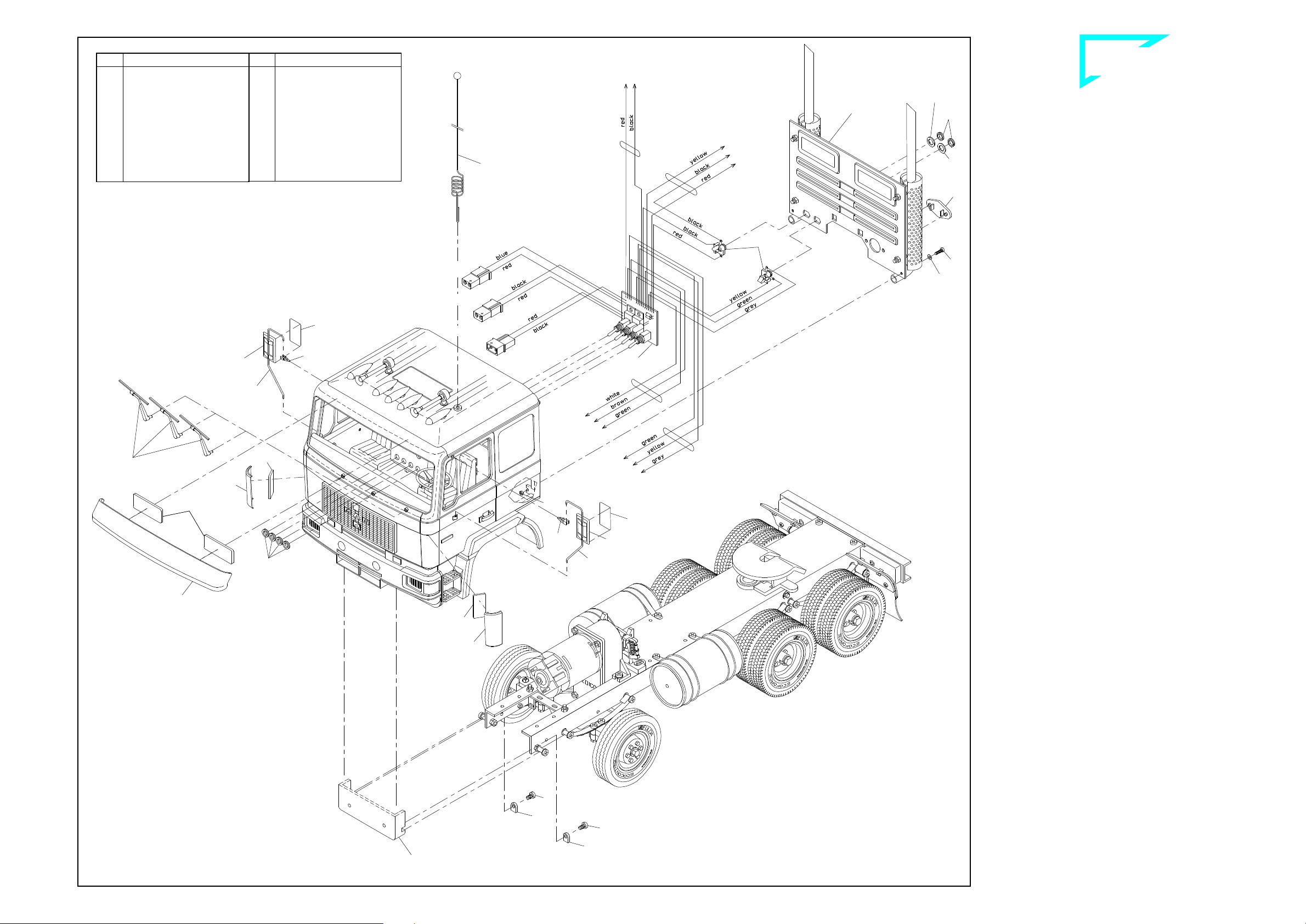
NP qÜÉ=ÉäÉÅíêáÅ~ä=ëóëíÉã=
The wiring diagram shows the cable connections for the individual
electrical components.
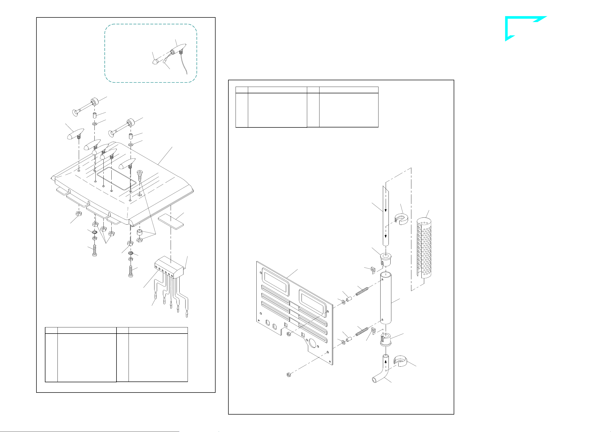
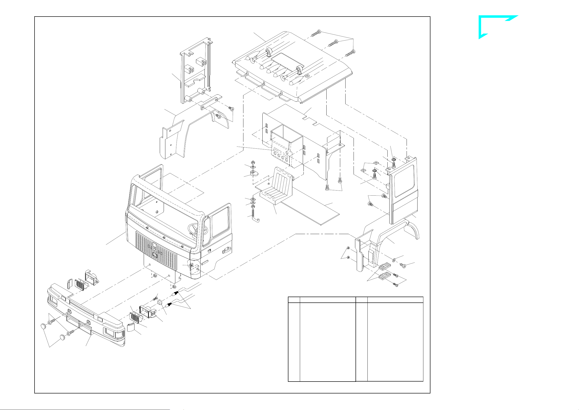
13.1 Mounting the switching panel and lamp PCBs
The switch panel is inserted into the seat rear panel of the cab. First
connect the bulbs and cables and then clip the lamp PCBs in place
at the front and rear in the supports provided for this purpose.
13.2 Information on the bulbs, troubleshooting
All the bulbs are 3-volt bulbs connected in series. This means that
the conductors are not each connected to the supply voltage, as in
an automobile. Instead, the ends are joined one to another to form a
chain and the ends of the chain are attached to the power supply.
Consequently just a single defective bulb will interrupt the entire cir-
cuit and none of the lamps in the chain will light. The best way to lo-
cate the defective bulb is to use a cable to bypass each of the bulbs
in the series, one after the other. When you bypass the defective
bulb, the rest in the chain will light. The reason for using a series
circuit, which may appear to be complicated, is the low power con-
sumption. 3-volt bulbs use far less power than 12-volt bulbs in rela-
tion to their brightness. The power consumed by a chain of up to five
3-volt bulbs is just 0.1 A in the series connection which we use; 12-
volt bulbs, by comparison, would draw 0.3 A.
13.3 Wiring the roof lamps
The bulb leads and the red and black cables from the switch panel are
attached at the screw terminal strip for the roof lamps. Then attach
the terminal strip under the roof as described in Section 3.2.
Be careful when clipping off the solder pins at the terminal strip as
there is a danger of shorts!
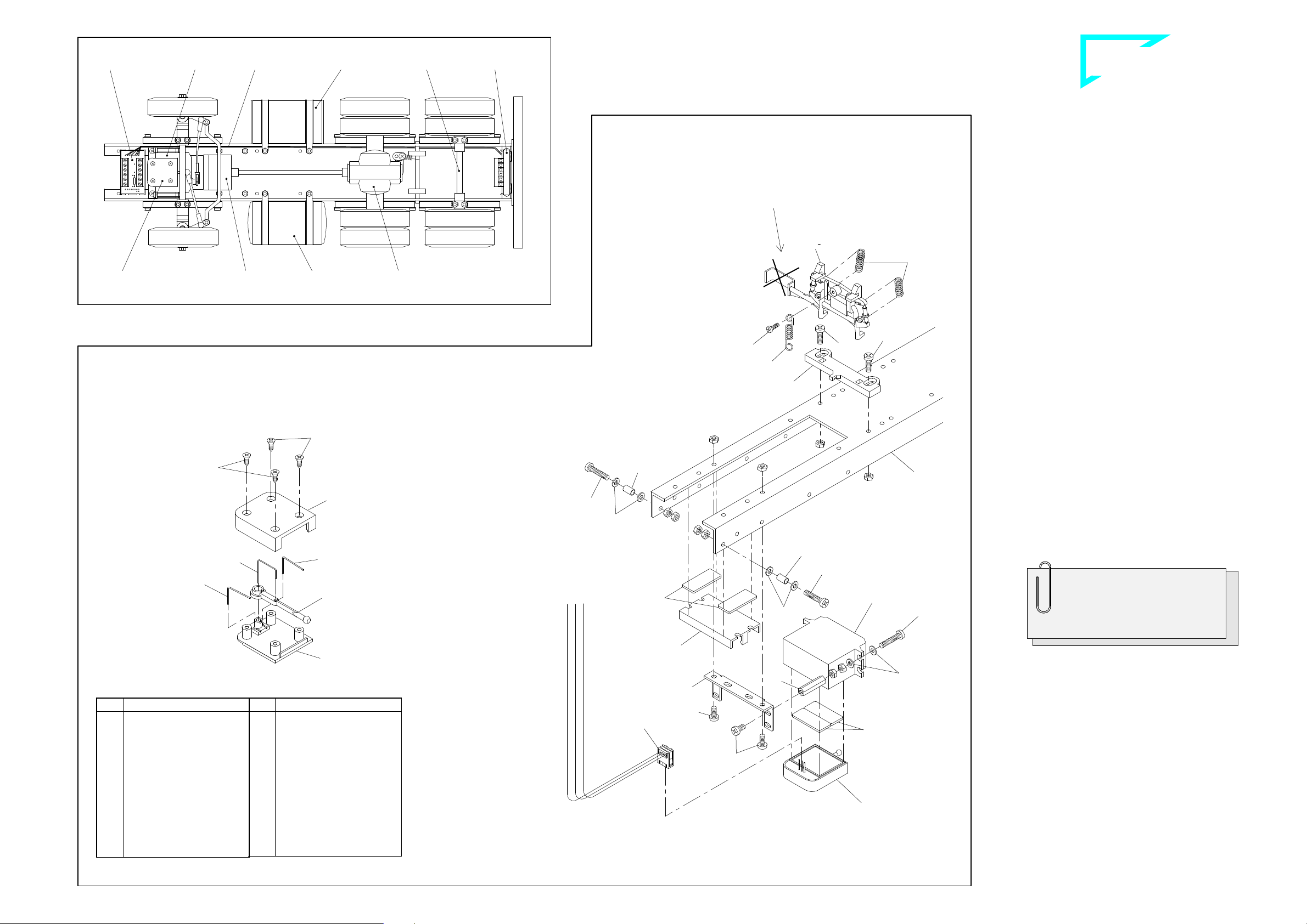
13.4 Wiring at the rear lamp PCB
(tail and brake lights, rear blinkers)
The red/black/yellow cable exiting the switch panel for the rear lamps
are routed under the frame and to the rear and connected to the PCB
- marked on the bottom with „H“ for rear - as shown in the illustration.
The green/yellow brake light cable coming from the speed controller
is also to be connected at this PCB. Once the bulb leads have been
attached, the PCB is clipped in place at the support which was previ-
ously affixed with adhesive pads.
Explanation: The green/yellow brake light cable connects the brake
light bulbs to ground when the vehicle is at a standstill. This circuitry
incorporates an element which limits the current to 750 mA and will
disable the circuit in case of an overload or short. Switching off the
supply voltage for about one second will reset this element, provided
that the reason for the malfunction has been corrected.
13.5 Wiring at the front lamp PCB
(headlamps, front blinkers)
The green/yellow/grey cable serving the lamps at the front also exits
from the switch panel and is routed below the frame and to the front
in exactly the same fashion. After connecting to the PCB - marked
on the bottom with „V“ for front - and connecting the bulb leads, the
lamp PCB is clipped in place in the support previously mounted.
13.6 Wiring the blinker switch
The green/brown/white cable for the blinker switch terminates in a
clamp-type connector (see therefore ill. 13a on page 11). This con-
nector is attached to the blinker switch (if the direction of travel does
not correspond to the blinking, please rotate it through 180°), mounted
beneath the steering servo, already illustrated in ill. 7.
57-e.DOC / K-MAN Page 10
Wiring diagram of the electrical equipment ill. 13
Supplied with the kit:
No. Assembly part
568
Antenna socket
708
Drive motor
929
Clamp-type connector
1580
Speed controller,
round tank short
---
Terminal strip, 6-pole
for roof lamps
---
Blinker switch
---
Drive battery 12 V
---
Charging cable with AMP-plug
---
Set of circuit boards f. complete
chassis with lamp PCBs
---
Switch panel with jack bushes
Not supplied with the kit:
RC receiver
Steering servo
Servo connecting cable
Cable for receiver voltage
Blinker switch
Steering servo
(not incl. in the kit)
white
brown
green
black
red
Brake light
yellow/green
Motor
yellow
yellow
yellow
yellow
red
black
Antenna socket
brown/red/orange
Terminal strip
roof lamps
Clamp type
connector
red
black
red
black
yellow
green
yellow
grey Head lamps -lh-/-rh-
RECEIVER
(not incl. in the kit)
to the battery box of the
remote control system
or alternative to the
switch panel (ill. 16)
Cable for receiver voltage
(not incl. in the kit)
Speed controller
Antenna cable
black
red
Blinker -lh-
Blinker -rh-
12V Battery
Switch panel
Charging
cable
black
red
blue
Jack bush
Jack bush
Knurled nut
Disc red
Knurled nut
Disc black
grey
green
yellow
Front lamp PCB
Set of circuit boards
for chassis
Blinker -rh-
Blinker -lh-
Rear lamp PCB
black
black
red
yellow
Brake lights
Rear lights
yellow/green
red
black
red
red
B-57-7
Control LED
red/black
V
H
V
H

`çãéäÉíÉ=háí==j^k=
`çãéäÉíáçå=çÑ=~ëëÉãÄäó=Öêçìéë
Blinking LED
Hazard warning
Lights
Receiver
Power / Charging
Main switch
OFF
ON
red
blue
black = minus pole (-)
red = plus pole (+)
Charging cable
from the
switch panel Switch panel Plug for the connection
to receiver battery
(+) red (5V)
(-) black
57-e.DOC / K-MAN Page 11
1. Put in the servo
connecting cable in
the matching colour
sequence, the wire ends
protruding about 10 mm.
3. Cut off the
wire ends and
insulate wires.
2. Carefully squeeze the
clamp-type connector
using a pair of pliers or
better, a small vice, until
the locks at the sides
snick audibly into place.
B-44-15
13.7 Connecting the speed controller
Connect the AMP socket with the yellow cables to the corresponding
AMP plug at the drive motor, and the AMP plug with the red/black
cables to the AMP socket at the switch panel.
The connection of the green/yellow brake light cable has already
been described in Section 13.4. The signal "brake light" is switched
by minus line, and it is time-triggered: As soon as one changes the
position of the control lever from either "forward" or from "reverse" to
the neutral position (switched-off), the brake light starts lighting for
approx. eight seconds. But as soon as the travelling operation is
started again, the brake light stops automatically its blinking, even
before having finished these eight seconds.
Attach the connecting socket with the brown/red/orange cable to one
of the receiver terminals. If the socket doesn't match the receiver,
you will need to add an adapter cable (not making part of this kit).
13.8 Starting the electrical system (see switches, ill.13b)
The electrical system is put into operation by turning on the main
switch; the LED blinks. Then the transmitter and receiver are switched
on, in this order. (Always switch off the receiver first and then the
transmitter!) If a speed controller has been installed, the brake lights
will go on. If the light switch is on, the headlamps, the roof lamps and
the tail lamps will light.
NQ qÜÉ=ëéÉÉÇ=ÅçåíêçääÉê=
The WEDICO speed controller is matched to the WEDICO-Bühler
motor. The electronics are permanently installed in a tank housing,
which should never be opened! Never apply force as this could
damage the speed controller and nullify any and all guarantee enti-
tlements. Prior to its supply, each speed controller is individually
tested and provided with a basic programming. In your particular
case, probably this general basic programming may not be the opti-
mal for the type of RC equipment you are using, but you of course
may change it (for further details please refer to the section 14.2
"programming").
14.1 Starting the speed controller
Switch the electrics on by the following sequence: start by the main
switch of the Electr. System, then switch on the transmitter, and finally
the receiver; keep your eye on the control LED. Before you make the
motor starts working remote-controlled, it is the speed controller which
has first to detect the programmed neutral position; this position sits
approx. in the centre on the control lever of your transmitter unit. Once
the speed controller has correctly detected said position, as a con-
firmation the control LED starts blinking for a ten times term. Only
then one may consider the speed controller as in state of readiness;
and now the motor power can be controlled for both senses of direc-
tion via the control lever.
14.2 How to programme the speed controller
Continue paying your attention to the control LED. For the correct ad-
justment of the control lever on the transmitter, set the shift controller
in neutral position; slide then the control lever into that position at
which you wish the motor to be "off". As a confirmation, lightly press
the programming key "4" on the speed controller (refer to next para-
graph). Do not move the control lever on the transmitter. Now, the
speed controller detects the neutral position, and the control LED
starts its ten times blinking.
Immediately after the blinking activity has started, slide the control
lever into the position for maximum "forward" speed; secure the lever
at this point. Do not move it. Even after the 10th blinking, the control
LED remains dark. As soon as the transmitter of your RC equipment
has detected the pulse corresponding to the maximum speed, the
control LED starts blinking again for a ten times term.
Immediately after the start of this blinking activity move the control
lever from the position "forward" directly to the position provided for
maximum "reverse" speed; secure the lever at this position. Again,
after the 10th blinking the control LED remains dark. Once the
transmitter of the RC unit has detected that pulse responsible for the
maximum speed, the control LED starts blinking again.
This signifies that the programming procedure of the speed controller
has been completed. The transmitter of the RC unit has successfully
detected the pulse coming from the speed controller, and now the
complete system is ready to operate.
If an error has been made during the programming procedure, the
system will not accept the new figures. In this case switch your Elec-
trical System off just for a short moment, and then switch it on again;
this procedure will re-activate the previous version of the program-
ming you have chosen for your speed controller. At this stage you
may start again any new programming.
14.3 Options for adjusting the speed controller
The holes at the rear tank cover are identified by numbers and serve
for the following types of adjustments, as there are:
•to "3": By a potentiometer, adjustment of the maximum motor speed
from 50 to 100% for the 1st direction (either forward or reverse, see
below),
•to "4": By key initiating the programming procedure,
•to "5": By potentiometer, adjustment of the maximum motor speed
from 50 to 100% for the 2nd direction (either forward or reverse, see
below).
It is by testing only that you find out which of both holes, either "3" or
"5", is responsible for the maximum motor speed of the direction
“forward” resp. the direction “REVERSE”.
Standard values on the speed controller are adjusted by manufactur-
ers. For any alteration of adjustment use a small screwdriver. Be
careful and don't apply any force!
14.4 Troubleshooting
No blinking activity on the
speed controller after hav-
ing put into operation
The position of the shifting lever
provided for the adjustments does
not correspond to the position of the
programming procedure. Make sure
the shifting lever has been set to neu-
tral position!
Motor does not react at all
Inadequate wire connections;
receiver voltage below 3 V;
main NiCads too low (below 8 V)
NR `Ü~êÖáåÖ=íÜÉ=ÇêáîÉ=Ä~ííÉêó=
For charging the drive battery connect as follows:
•the AMP-plug of the charging cable to that AMP-socket with the
blue/red cable of the cab's switch panel,
•the banana plugs of the charging cable to a charging unit.
Warning: Ensure that the banana plugs for the charging cable do
not touch while the charging cable is connected to the switch
panel.
At normal discharge levels it will take about 12 to 14 hours to re-
charge the battery (at 150 mA). Quick charging should be used only
in exceptional cases at a maximum of 1.5 A for one hour.
NS qÜÉ=êÉãçíÉ=Åçåíêçä=ëóëíÉã=
To operate the speed controller and the steering servo an inexpensive
2/4 channel system will be sufficient. Should you intend installing
additional electrical accessories, such as e.g. Diesel Engine Sound,
Art.-No. 189, for an RC equipment we would recommend a 2/4 chan-
nel unit, offering the installation of retrofit sets for the operation of
switching functions. Please ask your dealer for advice. Follow the in-
structions provided by the RC system manufacturer when installing
the receiver unit.
Should you don't wish the receiver voltage of your radio unit being
supplied via an independent battery, you may connect it to your 12V
truck battery. For this purpose you have to solder the wires of the re-
ceiver battery onto the switch panel (see ill. 16).
Note: By the installed voltage regulator (as a series fitting) the bat-
tery voltage of 12V on the switch panel is now automatically being
reduced to 5 volts.
NT pìééäÉãÉåí~êó=áåÑçêã~íáçå=
Attention: This special electrical equipment making part of our pro-
duction line "Complete Kits" will not fit any other electrical accessory
offered within the range of WEDICO System-Kits.
Should you once wish to extend your "Complete Kit" by
one or the
other electric accessory you will have to exchange this electrical sys-
tem. WEDICO offers you the following Electrical Systems:
•Art.-No. 783: The information to the semi-
trailer is transmitted via a
multi-frequency system. When adding an Infrared System (Art.-
Nr.
790 as transmitter, and Art.-
No. 791 as receiver), you may drive
your prime mover with any of a semi-trailer -
it does not depend on
the type of Electrical System your truck is equipped with.
•Art.-No. 796: The information is serially tra
nsmitted via one data
line only inside the prime mover. The information to the semi-
trailer
is transmitted via an Infrared Diode (transmitter).
Except these electrical components, all other accessories (for stan-
dard chassis) being offered within our programme WEDICO System-
Kits will fit your truck and/or semi-trailer and may be installed.
Switches of the switch panel ill. 13b
Attachment of the clamp-type connector ill. 13a
Charging the batteries ill. 15
Solder points for the connection of 5V receiver voltage ill. 16
At electrical connections, please
make sure that soldering points
are clean and plug connectors
are properly cramped!
Loose plugs and loosely twisted
wire connections cause faults
which are often hardly to locate.

`çãéäÉíÉ=háí==j^k=
`çãéäÉíáçå=çÑ=~ëëÉãÄäó=Öêçìéë
57-e.DOC / K-MAN Page 12
NU= ÉåÉê~ä=é~êíë=äáëí=
For gaining an easier overview of all single components and
their necessary quantity for the correct assembly of this model,
on the left side of this page you find a complete list including
each single item. For reasons of packaging some of the small
parts are packed in a higher number of pieces than necessary.
On the left side you find the quantity mentioned for each part.
Next to this column you find the numbers of the assembly parts
and their terms, followed by the EDP-numbers to be used
when re-ordering one or the other item.
Complete list of parts necessary for the assembly (please use EDP-number when ordering spare parts)
Qty.
No. Assembly part EDP-No.
11 655
Adhesive pad, double-sided
................................
20410
2 701
Jack bush 3.5mm
................................
26076
5 706
Roof lamp, chromed
................................
20352
2 707
Horn................................
................................
20350
1 708
Bühler motor including
14 teeth pinion
................................
22298
2 709
Lamp cap................................
................................
20264
1 710
Carrier plate for support PCB
................................
23334
15 713
Bulb 3V ................................
................................
20310
2 714
Mud guard................................
................................
21272
1 715
Mudguard support “X“
................................
21275
1 716
Mudguard support “O““
................................
21274
2 717
Mud flap................................
................................
24074
1 718
Antenna with ball
................................
20432
1 719
Cover for blinker switch
................................
24920
1 720
Base for blinker switch
................................
24916
2 721
Spring, single bent
................................
25066
1 722
Spring, double bent
................................
25068
2 723
PCB support, small
................................
21530
1 724
Lever for blinker switch
................................
24918
1 760
Servo angle 1, small
................................
26122
1 789
Fork head................................
................................
20400
2 908
Stop nut M3................................
................................
30568
1 929
Clamp-type connector, 3-pole
................................
21772
8 1160
Drive axle tyre “Ecoforce“
................................
28172
1 1254
Wind deflector -lh-, MAN
................................
25422
1 1255
Wind deflector -rh-, MAN
................................
25420
1 1256
Roof, Complete Kit MAN “C”:
white ................................
................................
28586
red................................
................................
28598
black ................................
................................
28600
1 1257
Rear panel, Compl. Kit MAN “C”:
white ................................
................................
28584
red................................
................................
28594
black ................................
................................
28596
1 1258
Sun visor MAN
................................
25732
1 1390
Track rod, flat
................................
29312
1 1580
Speed controller, round tank short
................................
29764
1 ---
Sticker for switch
................................
20558
1 ---
Drive battery 12V
................................
21441
1 ---
Terminal strip, 6-pole
................................
21878
1 ---
Charging cable with AMP-plug
................................
25946
1 ---
Switch panel with jack bushes
................................
26068
1 ---
Set of circuit boards
for complete chassis
................................
26072
1 ---
Decal................................
................................
---
Qty.
No. Assembly part EDP-No.
1 568
Antenna socket, complete.
................................
20430
2 573
Mirror black................................
................................
20398
2 574
Mirror foil................................
................................
20366
1 600
Front panel MAN:
white................................
................................
25634
red ................................
................................
25638
black................................
................................
25640
1 602
Side panel -lh-, MAN:
white................................
................................
25658
red ................................
................................
25662
black................................
................................
25664
1 603
Side panel -rh-, MAN:
white................................
................................
25650
rot................................
................................
25654
black................................
................................
25656
1 605
Fender -lh-, MAN
................................
25416
1 606
Fender -rh-, MAN
................................
25418
1 607
Door -lh-, MAN:
white................................
................................
25692
red ................................
................................
25696
black................................
................................
25698
1 608
Door -rh-, MAN:
white................................
................................
25684
red ................................
................................
25688
black................................
................................
25690
2 609
Door inner cover, MAN
................................
25440
2 610
Door lock, MAN
................................
25434
2 611
Door handle, MAN
................................
25444
4 612
Hinge bushing, door
................................
25442
2 613
Door shield, MAN
................................
25448
2 614
Door lock bushing
................................
25446
4 615
Door hinge, MAN
................................
25436
2 616
Pin for door hinge ∅1.5 x 43.5
................................
25438
1 617
Radiator grille, MAN
................................
25414
1 618
Frame radiator grille
................................
25413
1 619
Bumper MAN ................................
...............................
25392
2 620
Reflector MAN
................................
25404
2 621
Blinker lens MAN
................................
25432
1 622
Dashboard MAN
................................
25430
1 623
Windscreen MAN
................................
25628
2 624
Headlight lens, MAN
................................
25338
2 628
Mirror support, MAN
................................
25426
1 629
Insulating disc, red
................................
26230
1 630
Insulating disc, black
................................
26232
2 631
Reflector foil MAN
................................
25362
6 632
Hinge support................................
...............................
25704
2 633
Bushing 27mm (to be cut off the
plastic tube 70mm)
................................
20210
Qty.
No. Assembly part EDP-No.
1 62
Gear wheel with joint socket
................................
20326
1 63
Shaft 5 x 24 for gear 116
................................
20330
2 64
Ball joint ................................
................................
20328
1 66
Standard differential, mounted
................................
21234
1 68
Rear axle 144mm
................................
20126
4 70
Spring carrier, plastic
................................
20138
1 71
Standard fifthwheel
................................
20008
1 72
Bar for kingpin
................................
20010
1 73
Shaft for fifthwheel
................................
20012
2 74
Draw spring................................
................................
20462
1 75
Door handle ................................
................................
20084
1 76
Door lock ................................
................................
20086
2 93
Muffler 80mm................................
................................
20074
2 95
Exhaust tail pipe
................................
20078
4 96
Exhaust cap ................................
................................
20079
2 103
Seat................................
................................
20080
15 109
Nut M2................................
................................
21208
6 111
Self-cutting screw M3 x 8
................................
20223
12 114
Screw M2 x 6
................................
21268
5 115
Screw M2 x 8
................................
21269
2 176
Coil spring for lever
................................
20260
4 210
Knurled nut M5
................................
20440
1 222
Seat rear panel
................................
21962
1 225
Battery carrier plate
................................
21966
2 228
Windscreen wiper -lh-
................................
21972
2 228
Windscreen wiper -rh-
................................
21974
2 282
Fixing clip................................
................................
20360
5 289
Lens for roof lamp, orange
................................
20404
2 341
Blinker lens high, orange
................................
20304
4 342
Lens/rear light high, red
................................
20308
1 359
Drive shaft 145mm
................................
20716
2 366
Lens flat, black 23864
2 372
Exhaust shield, chromed
................................
20356
4 383
Fixing cap for exhaust shield
................................
20426
1 390
Welsh plug, oval
................................
20292
1 391
Shim 5 x 10 x 1
................................
23346
8 397
Tapping screw 2.2 x 6.5
................................
23690
2 459
Rubber funnel for reflector 24518
4 463
Access, fender Volvo/MAN
................................
24256
2 470
Mirror hinge, bottom
................................
24292
1 476
Locking device
................................
24302
1 477
Base for locking device
................................
24300
2 483
Exhaust manifold
................................
21202
1 498
Switch dashboard
................................
24714
4 503
Insulating strip
................................
20296
2 560
Knurled nut M6
................................
---
4 564
Countersunk
tapping screw 2.2 x 4.5
................................
25072
Qty.
No. Assembly part EDP-No.
65 ---
Nut M3
................................
................................
20040
6 1
Screw M3 x 6
................................
20016
27 2
Screw M3 x 8
................................
20018
10 3
Screw M3 x 12
................................
20022
13 4
Screw M3 x 16
................................
20024
10 5
Screw M3 x 20
................................
20224
2 6
Screw M3 x 25
................................
20026
12 10
Self-cutting screw M3 x 6
................................
20222
15 12
Square nut M3
................................
20044
49 13
Washer 3.2................................
................................
20046
1 14
Spring washer 3.2
................................
20056
8 15
Serrated washer 3.2
................................
20054
4 16
Stud bolt M3 x 18
................................
20258
4 17
Hex head screw M4 x 8
................................
20036
2 18
Hex head screw M4 x 25
................................
20038
7 19
Nut M4................................
................................
20042
8 20
Washer 4.3................................
................................
20048
1 21
Tapping screw 2.2 x 4.5
................................
20052
2 24
Washer 2.2................................
................................
21210
2 25
Retaining washer 3.2
................................
20058
20 26
Bushing 4 x 0.5 x 7
................................
20088
2 27
Axle tube ................................
................................
20150
2 28
Threaded bushing 20mm
................................
20070
2 29
Ball bolt M3 ................................
................................
20170
3 30
Ball socket ................................
................................
20172
6 32
Spring long, “AF“
................................
20132
8 33
Spring medium, “AF“
................................
20134
6 34
Spring short, “AF“
................................
20136
2 36
Threaded rod M2 x 50
................................
20268
4 41
Half-axle guard
................................
20144
2 42
Steering lever
................................
20146
1 44
Link lever ................................
................................
20148
1 45
Frame 3-axle chassis, 432mm
................................
20254
1 46
Frame tail piece
................................
20002
1 47
Bumper, rear
................................
20006
1 48
Tank tube, polished
................................
20120
2 49
Tank cap, flat................................
................................
20122
4 52
Rim, grey ................................
................................
20128
6 52
Rim, chromed
................................
20420
2 53
Standard tyre “Ecocontrol“
................................
28840
4 54
Clamp fitting, standard frame
................................
20124
1 55
Front axle ................................
................................
20142
1 56
Steering wheel
................................
20156
4 57
Screw M3 x 10
................................
20020
1 58
Case for gear 116
................................
20318
1 59
Cap for gear 116
................................
20320
(1) 60
Motor pinion, white, 14teeth
................................
20300
1 61
Double pinion for gear 116
................................
20324
This manual suits for next models
3
Other WEDICO Motorized Toy Car manuals