WEDICO Mercedes ACTROS Driving model C User manual

80-e.DOC / K-Actros 29.01.2004 Page 1
We are glad that you have decided on one of the precious WEDICO
truck models! For the manufacture of individual parts WEDICO uses
durable materials of high quality - rarely to find in these days. This
guarantees durability and enjoyment of your model for years to come.
If you should ever require replacement parts, please get in touch
with your dealer or directly with WEDICO. For order purpose it is
important using not only those EDP-numbers mentioned within the
general parts list (see last page of this instruction) but also indicating
the necessary details concerning colour, quantity and exact term of the
spares required. You may be assured that WEDICO will supply the
replacement part as quick as possible.
qÉÅÜåáÅ~ä=Ç~í~W=
Truck tractor:
Length...............................................458 mm
Width.................................................190 mm
Height................................................226 mm
Track (tread) front..............................140 mm
Track (tread) rear...............................116 mm
Weight with motor drive and NiCads.....3.5 kg
Superstructure:
Components of die cast aluminium
and aluminium sheet,
stainless steel threaded connectors
and bending wire components,
high impact plastic components.
Cab tiltable. The roof -together with the
top device of the rear panel- is detachable.
Model is prepared for R/C-installation.
®WEDICO
Art.-No. 80 white
Art.-No. 81 blue
Art.-No. 82 yellow
`çãéäÉíÉ=háí=
jÉêÅÉÇÉë==^`qolp=
aêáîáåÖ=ãçÇÉä==`=
B-80-01
B-80-02
Technical data
Drive Motor: WEDICO-
Bühler electric motor, rated voltage
12 volts, 7-
segment collector. Idling speed 6000 rpm.
Torque 5 Ncm (approx. 500 pcm) at 4000 rpm.
Power drawn under load at max. torque approx. 3 A.
Idling power consumption with connected gearing
and one differential approx. 0.5 A.
Gearbox Standard single speed 2-
stage spur gearbox with
self-lubricating gearwheels. Reinforced housing.
Gear ratio 5.6 : 1.
Power
transmission
Stainless steel drive shafts with ball joints between
gearbox and differential. Differential gear.
Gear ratio 2 : 1.
Superstructure
Frame made of aluminium section, 2 mm thick; to
r-
sion resistant.
Rear bumper made of section 2 mm thick.
3-part (rear) to 4-
part (front) stainless steel leaf
spring packages on all axles.
Soft rubber tires with reproduction of original tread
pattern.
Fasten
ing components made of stainless steel. All
body parts are made from aluminium sheet and
aluminium die cast 1.5 to 2 mm thick.
Finish
Extremely hard epoxy powder coating. Excellent
base when repainting for special purposes.
Assembly During assembly it is advisable following the s
e-
quence given by these instructions. Observe the
notes explaining the various steps in assembly and
use only those parts which are provided; this will
insure a correct result of assembly.
WEDICO system kits are known for their exact fit.
© 2001 by WEDICO, P.O. Box 20 04 18, D - 42 204 Wuppertal, Germany.
We can assume no liability for technical or typographical errors.
We reserve the right to incorporate technical modifications.
Duplication and reproduction only with our express consent.

`çãéäÉíÉ=háí==^`qolp=
`çãéäÉíáçå=çÑ=~ëëÉãÄäó=Öêç éë
114
114
24
109
109
24
114
109
114
109
982
983
984
985
986
987
988
989
990
991
NdÉåÉê~ä=
1.1 The assembly instruction
On the left side you find the illustrations of the assembly groups in-
cluding the part lists indicating the necessary components. On the
right side, marked by the corresponding number of illustration, the in-
structions for the proper assembly.
1.2 Screws and other small parts
M3 nuts are generally not provided with an identification number. As
a help easier to find out screws and small parts, please see ill. 1
which is showing you the most important components at original size.
OmêÉãç åíáåÖ=íÜÉ=ÑÉåÇÉêë=
Slide the stepboards 986, 988 and 990 into the lateral guiding lines on
the left fender 982; in the same sense add now the steps 987, 989
and 991 to the right fender 983. Once the steps are sitting correctly
and close, secure them behind the fenders by twisting the protruding
pins by 30 degrees.
Afterwards set the left fender with it's collar on top of the left fixing
plate 984. Secure both parts with screws 114 and nuts 109; for the
attachment to the slotted fixing hole you need one additional U-washer
24. The assembly of the right fixing plate 985 with the right fender
has to be done in the same sense.
80-e.DOC / K-Actros Page 2
M4 x 25
Part no. 18
M4 x 8
Part no. 17
M3 x 35
Part no. 949
M3 x 25
Part no. 6
M3 x 20
Part no. 5
M3 x 16
Part no. 4
M3 x 12
Part no. 3
M3 x 10
Part no. 57
M3 x 8
Part no. 2
M3 x 6
Part no. 1
Self-cutting screw M3 x 8
Part no. 111
Self-cutting screw M3 x 8
Part no. 355
Countersunk screw M3 x 6
Part no. 7
M2 x 8
Part no. 115
M2 x 6
Part no. 114
M2 x 5
Part no. 742
M2 x 4
Part no. 741
Countersunk screw M2 x 8
Part no. 907
Countersunk screw M2 x 5
Part no. 926
Tapping screw 2,2 x 9,5
Part no. 479
Tapping screw 2,2 x 6,5
Part no. 397
Tapping screw 2,2 x 4,5
Part no. 21
Countersunk tapping screw 2,2 x 6,5
Part no. 727
Countersunk tapping screw 2,2 x 4,5
Part no. 564
Nut M4
Part no. 19
Nut M3
---
Nut M2
Part no. 109
Stop nut M3
Part no. 908
Square nut M3
Part no. 12
Knurled nut M5
Part no. 210
Shim 5 x 10 x 1
Part no. 391
Washer 4.3
Part no. 20
Washer 3.2
Part no. 13
Washer 2.2
Part no. 24
Spring washer 3.2
Part no. 14
Serrated washer 3.2
Part no. 15
Retaining washer 3.2
Part no. 25
B-233-3
Qty.
No. Assembly part
2 24
Washer 2.2
6 109
Nut M2
6 114
Screw M2 x 6
1 982
Fender with entry, -lh-
1 983
Fender with entry, -rh-
1 984
Fixing plate f. fender, -lh-
1 985
Fixing plate f. fender, -rh-
Qty.
No. Assembly part
1 986
Top stepboard, -lh-
1 987
Top stepboard, -rh-
1 988
Centre stepboard, -lh-
1 989
Centre stepboard, -rh-
1 990
Bottom stepboard, -lh-
1 991
Bottom stepboard, -rh-
For securing purpose
use pliers to twist the
pins of the stepboards
by 30 degrees
Screws and other small parts at 1:1 ill. 1
Premounting the fenders ill. 2

`çãéäÉíÉ=háí==^`qolp=
`çãéäÉíáçå=çÑ=~ëëÉãÄäó=Öêç éë
109
109 827
975
975
974
973
827
926
968
970 827
971 972
971
972
827
972
971
975
975
972 971
827
970
968
926
827
973
974
907
977
979
981
470
470
611
980
727
741
727
981
978
976
980
611
470
470
741
907
727
727
PmêÉãç åíáåÖ=íÜÉ=Çççêë
The following text describes the assembly of the left door only; the
attachment of the right-hand door has to be done accordingly.
3.1 Assembly of the hinge parts (ill. 3a)
Drawings in the upper line show the assembly of the right-hand side,
those in the lower line the assembly of the left-hand side.
When adding the hinge pins make sure that all hinge components
are in correct position. This is very important for both, the function
and the correct fitting of the cab door. For a better orientation
some of the components are specially marked (see corresponding
arrows in the drawing). Please refer to ill. 3b which is showing not
only the hinge components at original size and completely assem-
bled but also the correct position of the angled hinge components
(length of leg and angle position).
1st step: Lay the hinge support 970 from inside into both long open-
ings on the left inside door panel 968; press then one nut 109 into
the hexagonal slot of the support and fix it from outside using one
countersunk screw 926.
2nd step: Push one hinge pin 827 into the hole on the longer leg
(note the corresponding mark!) of one of the door hinges 972 until
the top of the pin sits flush. From the top press then this pin through
that hole provided for on the support you have already pre-mounted.
On the bottom insert a second hinge pin 972 (note the corresponding
mark!); use an appropriate tool to push it into place until the upper
door hinge snaps into that slot on the inside door panel. The two
door hinges 971 have to be mounted in the same way.
3rd step: Now set the door hinge 974 between both already pre-
mounted angled hinges (use the centre holes) and fix it with a further
pin 827. Afterwards the shorter leg (note the corresponding mark!) of
the hinge 973 has to be added to the other hinges in the same way.
4th step: Attention! The holes on the supports 975 are not central!
Note the correct position of the corresponding mark when mounting
the supports along with pins 827 to the free holes of the hinges!
3.2 Assembly of the door (ill. 3c)
First remove the protecting foil from the door window 981. Now use
the mirror support 470 as well as the tapping screw 907 in order to
premount the following parts: door 976, door window 981, door lock
980 and inside door panel 968. Please pay attention to the correct
position of the door lock!
For easier differentiation both door trims 978 and 979 are marked by
letters: „L“ = left, „R“ = right. Lead one door handle 611 through the
left door cover 978. Afterwards set the door trim along with the han-
dle onto the proper door, whereby the short axles on the door handle
must sit exactly inside the half-round bearing of the door panel. With
two countersunk screws 727 fix then door panel with door and trim.
Using one screw 741 add finally the second mirror support 470 onto
the top of the door.
80-e.DOC / K-Actros Page 3
Qty.
No.
Assembly part
2 109
Nut M2
14 827
Pin for door hinge
∅1 x 36mm
2 926
Countersunk screw
M2 x 5
1 968
Inside door panel, -lh-
1 969
Inside door panel, -rh-
2 970
Support 2, door hinge
4 971
Door hinge 2
4 972
Door hinge 3
2 973
Door hinge 1
2 974
Door hinge 4
4 975
Support 1, door hinge
B-233-2
1st step 2nd step 3rd step 4th step
Important!
The door trims will
correctly fit only if
each opening for the
door handles lays
at the bottom.
Qty.
No.
Assembly part
4 470
Mirror hinge, bottom
2 611
Door handle
4 727
Countersunk tapping
screw 2.2 x 6.5
2 741
Screw M2 x 4
2 907
Countersunk screw
M2 x 8
Qty.
No.
Assembly part
1 976
Door -lh-
1 977
Door -rh-
1 978
Door trim -lh-
1 979
Door trim -rh-
2 980
Door lock
2 981
Door window
Assembly of the hinge parts ill. 3a
Assembly of the doors ill. 3c
Top view of the assembled hinge components ill. 3b
M 1:1
Right
side
Left
side
„L“
„L“
„R“
„R“
B-233-2b

`çãéäÉíÉ=háí==^`qolp=
`çãéäÉíáçå=çÑ=~ëëÉãÄäó=Öêç éë
109
109
742
742
1046
1046
742
1046
14 12
14
14
1
1
1
1
1
996
713 1000
998
997
995
994
993
992
742
2
2
12
75
12
76
13
13
75
14
13
76
13
12
4,5mm
4
4
568
15
26
707
707
26
14
14
1386
15
Q^ëëÉãÄäáåÖ=íÜÉ=êççÑ=ëÉÅíáçå=
4.1 Cutting threads
Threads have to be cut into six screw holes on the roof. Before you
start the proper assembly, use self-cutting screws 111 supplied with
this kit to cut these threads. You should lubricate the screw and the
screw holes (using a little petroleum jelly, for instance) before doing
so and afterwards use a soft cloth to remove excess lubricant.
4.2 Antenna socket and horns
Affix the components for the antenna socket 568 to the roof 1386 as
shown in the illustration. Please note that the antenna cable from the
remote control receiver will have to be soldered to the antenna
socket.
The horns 707 are fitted with bushings 26 and spring washers 14 and
then affixed, through the holes provided in the roof, using screws 4,
nuts M3 and serrated washers 15.
4.3 Assembly of roof, locking device and rear panel
When adding the assembly of the roof and upper rear panel to the
cab, do not tighten the fasteners as both units have to be detachable.
For locking the roof, two door locks catch behind those metal sheets
specially provided for that on the side panels.
To a door handle 75 add one nut M3 and tighten it. Then slide the
door lock 76 over it and screw on one square nut 12. Fix door handle
and door lock that way that they are facing same direction. When
fastening the door lock it is advisable securing it with pliers. Afterwards
add a further nut M3. Once you have added one spring washer 14
and one washer 13, slide the handle through that hole provided for
on the left-hand roof locking plate 994. From behind add now one
washer 13 and fasten the unit using two nuts M3. By the same way
add a door handle to the right-hand side roof locking plate 995.
Now provide a guide post on each locking sheet by using each one
bolt 1046 and screws 742. Build another similar post onto the guide
sheet 996; as the hole is not central please note the correct side (di-
mension in the illustration is of 4.5) when adding it. Use two screws 1
to fix the guide sheet underneath the roof.
Press now the lenses 997 and 998 into those holes provided in the
front of the roof. Feed the wires from each bulb 713 through the
holes provided on both roof locking sheets.
Fix the left hand roof locking sheets onto the underside of the roof
with screws 1. Use screws 742 and nuts 109 to add the 7-pole pin
terminal 1000 to the right hand roof locking sheet. Once all wires
have been connected (see chapter 4.5), similarly to the left-hand one
fix the right-hand roof locking sheet underneath the proper roof. Af-
terwards insert the bulbs into the roof lamp lenses.
Fixing the rear panel 993 to the roof: For this purpose slide each one
square nut 12 with one spring washer 14 into those slots on the two
fixing links underneath the roof. Set the rear panel into the guide
groove and squeeze it by tightening screws 2.
Note:Those free holes on the rear panel 993 are provided for the at-
tachment of the side spoilers (accessories).
80-e.DOC / K-Actros Page 4
Qty.
No. Assembly part
2 111
Self-cutting screw M3 x 8
Qty.
No. Assembly part
2 ---
Nut M3
2 4
Screw M3 x 16
2 14
Spring washer 3.2
2 15
Serrated washer 3.2
2 26
Bushing 4 x 0.5 x 7
Qty.
No. Assembly part
1 568
Antenna socket, compl.
2 707
Horn
1 1386
Roof, Complete Kit
ACTROS “C“
Antenna socket and horns ill. 4.2
Qty.
No.
Assembly part
8 ---
Nut M3
6 1
Screw M3 x 6
2 2
Screw M3 x 8
4 12
Square nut M3
4 13
Washer 3.2
4 14
Spring washer A 3.2
2 75
Door handle
2 76
Door lock
2 109
Nut M2
2 713
Bulb 3V, 100mA
5 742
Screw M2 x 5
Qty.
No.
Assembly part
1 993
Rear panel, top ACTROS
1 994
Locking sheet / roof, -lh-
1 995
Locking sheet / roof, -rh-
1 996
Guide sheet for roof
1 997
Lens, roof lamp -lh-
ACTROS
1 998
Lens, roof lamp -rh-
ACTROS
1 1000
7-pole pin terminal
3 1046
Bolt with thread
Assembly of roof, locking device and rear panel ill. 4.3
B-80-2
B-80-1
B-223-1
Cutting threads ill. 4.1

`çãéäÉíÉ=háí==^`qolp=
`çãéäÉíáçå=çÑ=~ëëÉãÄäó=Öêç éë
1002
1001
1004
1003
21
21
564
564
564
13
2
2
2
1038
995
1000
1001
564
564
624
624
1005
1006
1007
1008
1009
1010
1011
1015
498
56
2
4.4 Fixing the air filter
Using two panel screws 21, start by mounting the side part 1004 onto
the outside part 1002. With countersunk screws 564 add afterwards
the inside part 1003 to the outside part 1002. Finally fix this unit with
screws 2 onto the rear panel, and with screws 2and washers 13
onto the roof.
4.5 Connecting diagram for the clamp-type terminals
When removing the roof, you may also disconnect the cabling at the
pin and socket connector. For this purpose use the 7-pole pin termi-
nal 1000 and the 7-pole socket terminal 1001. Accordingly to the il-
lustration, a resistor 1038 for the roof lamps has to be mounted onto
the pin terminal and the antenna cable has to be soldered to the an-
tenna socket.
The illustration shows the different connections. To make both sides
clearly visible, you find two illustrations of the pin terminal 1000.
Installing the Diesel Engine Sound, Art.-No. 193: The Diesel
engine sound includes the loudspeaker, which can be stuck into
the area provided on the underside of the roof, using double sided
adhesive pads.
RmêÉJ~ëëÉãÄäó=çÑ=íÜÉ=Ä ãéÉê
Assembly of headlights and blinkers
Cut the piece of reflector foil 1037 (no ill.) to size according to the
size of the headlight housings 1006 and 1007 and lay these pieces
into the lamp cases. Accordingly to the drawing, afterwards press
one bulb into each of the clips provided on the lamp housings. As per
drawing feed the wires through the narrow slots inside these lamp
cases outwards.
First fit the lens 1010 of the left blinker into the corresponding opening
on the bumper 1005 by pressing it into place from the inside, flush to
the left, and add a headlight lens 624 with the funnel-shaped ribbing
showing outwards. The lugs on the top and bottom of the outer left
blinker lens 1008 fit into the slots in the grooves on the left bumper
side. Now set the left-hand lamp housing 1006 that way onto the fix-
ing domes inside the bumper that the upper collar of the blinker lens
gets fixed behind the cut-out of the headlight housing. Finally fix the
housing with screws 564. Do the assembly of the right-hand head-
light housing 1007 in the same way.
SmêÉé~ê~íáçå=çÑ=íÜÉ=Ç~ëÜÄç~êÇ
Peel the stickers showing the instruments and switches from the de-
cal sheet 1014 and stick them in place on the dashboard 1015. With
screw 2fix then the shift for the switch 498 onto the dashboard and
press the steering wheel 56 onto this shift.
Fixing the air filter ill. 4.4
80-e.DOC / K-Actros Page 5
Connecting diagram for the clamp-type terminals ill. 4.5
Pre-assembly of the bumper ill. 5 Preparation of the dashboard ill. 6
Qty.
No.
Assembly part
1 1038
Resistor for roof lamps,
80.6 Ω/ 0.5 W
Space for the attachment
of the loudspeaker
of Art.-No. 193
Cab roof
Loudspeaker of
Art.-No. 193
Roof lamps
Connection of roof lamps
from switch panel
Antenna receiver
Loudspeaker conne
c
tion
to the engine sound
Antenna socket
B-233-5
Stickers taken
off the decal
sheet 1014
Inserting the bulbs
B-80-3 B-233-4b
B-233-5
Qty.
No.
Assembly part
1 2
Screw M3 x 8
1 56
Steering wheel
1 498
Switch dashboard
Qty.
No.
Assembly part
1 1014
Decal sheet ACTROS
1 1015
Dashboard ACTROS
Qty.
No.
Assembly part
1 1008
Blinker lens outside -lh-
ACTROS
1 1009
Blinker lens outside -rh-
ACTROS
1 1010
Blinker lens -lh- AC-
TROS
1 1011
Blinker lens -rh- AC-
TROS
1 1037
Reflector foil
Qty.
No.
Assembly part
4 564
Countersunk tapping
screw 2.2 x 4.5
2 624
Headlight lens, MAN
4 713
Bulb 3V, 100mA
1 1005
Bumper ACTROS
1 1006
Headlight housing -lh-
ACTROS
1 1007
Headlight housing -rh-
ACTROS
Qty.
No.
Assembly part
1 1002
Air filter, outside part
ACTROS
1 1003
Air filter, inside part
ACTROS
1 1004
Air filter, side part
ACTROS
Qty.
No.
Assembly part
3 2
Screw M3 x 8
1 13
Washer 3.2
2 21
Tapping screw 2.2 x 4.5
3 564
Countersunk tapping
screw 2.2 x 4.5
1 1001
7-pole socket terminal

hçãéäÉííJ_~ ë~íò=^Åíêçë=
cÉêíáÖëíÉää åÖ=ÇÉê=_~ Öê ééÉå
`çãéäÉíÉ=háí==^`qolp=
`çãéäÉíáçå=çÑ=~ëëÉãÄäó=Öêç éë
1387
109
109
114
114
1017
1
12
12
12
12
12
1
1018
222
1022
1
1
1025 1025
1016
1019
1021
1020
15
15
355
355
1
1
1
1
1
80-e.DOC / K-Actros Page 6
T^ëëÉãÄäáåÖ=íÜÉ=Å~Ä=
7.1 Cutting threads (see small drawing)
Threads have to be cut into eight screw holes on the front panel. Use
self-cutting screws 111 to cut these threads by the same method as
described under chapter 4.1.
7.2 Mounting the front- and side panels
Don't tighten all screwed connections as the cab skeleton has still to
be adjusted.
Start by securing the left-hand fixing plate 1020 into the suiting cut-
out made for this purpose on the front panel 1016; use countersunk
screw 355, serrated washer 15 and nut M3 for that. Afterwards slide
two square nuts 12 into both upper slots on the fixing frames of the
left side panel 1017; then fix the side panel with screws 1onto the
fixing plate. Make sure that the external sides of both, front- and side
panels, are exactly in alignment. Now mount the right-hand fixing
plate 1021 and the right-hand side panel 1018 in the same way. Slide
another square nut 12 into each of the rear upper fixing slots on the
side panels; with screws 1secure then the fixing angle 1022 into
place between the two side panels.
At this stage of assembly adjust the external contours of the pre-
mounted cab with the roof assembled at chapter 4.1. From top slide
that rear panel you have already mounted onto the roof into the verti-
cal grooves on the side panels. Both lateral fixing plates mounted
onto the cab, as well as the fixing angle include fixing holes; these
holes have to be aligned with those pilots which previously were
added to the roof. At the screwed connections on the panels all com-
ponents may now suitably be moved.
Once all parts have been adjusted correctly, tighten all nuts and
screws.
7.3 Doors, windscreen and dashboard
Set the doors you have assembled at stage 3.2 into their places on
the cab. With screws 1 fix the hinge supports to the front panel. When
closed, the doors should stay parallel to the side panel; by moving
the supports you achieve the final adjustment.
Press the windscreen 1019 into the front panel. For this purpose slide
the screen from inside into the groove on the left side of the front
panel. In order to fit the screen into the groove on the right hand side
you need to bow it inwards slightly, then press it forward gently until
it clicks into place. Finally attach the dashboard with screws 1onto
the front panel.
7.4 Seat- and lower rear panel
First pass the switch toggles at the switch panel through the holes
provided in the seat rear panel 222; secure from the front using
four knurled nuts 210 (see therefore illustration 14).
Attach the switch sticker onto the seat rear panel - above the four
holes for the toggle switches on the switch panel - ; the letters indi-
cating the switches are now upside down. Slide one square nut 12
into each of the slots on the centre fixing frames of the side panels.
Afterwards attach the seat rear panel 222 that way that those sides
with the fixing holes lay underneath the fixing frames on the side
panels; insert screws 1from the bottom and tighten them on the right
side. Don't tighten the screws on the left-hand side as the left side
panel has still to remain moveable. With screws 114 and nuts 109 fix
the stopping devices for the cab lock 1025 onto the lower rear panel
1387. Slide the lower rear panel into the suiting groove on the right
side panel, press then the left side panel outwards and slide the rear
panel also into same groove. Now tighten the screws on the left side
on the seat rear panel.
Assembling the cab ill. 7
Qty.
No. Assembly part
2 ---
Nut M3
16 1
Screw M3 x 6
10 12
Square nut M3
2 15
Serrated washer A 3.2
4 109
Nut M2
2 111
Self-cutting screw M3 x 8
4 114
Screw M2 x 6
1 222
Seat rear panel
2 355
Countersunk screw
M3 x 8
1 1016
Front panel ACTROS
1 1017
Side panel, -lh-
ACTROS
Qty.
No. Assembly part
1 1018
Side panel, -rh-
ACTROS
1 1019
Windscreen ACTROS
1 1020
Fixing plate for front, -lh-
1 1021
Fixing plate for front, -rh-
1 1022
Fixing angle for
side panels
2 1025
Stopping device for
cab lock
1 1387
Rear panel, bottom
Complete Kit
ACTROS. “C“
---
Switch sticker
B-80-4
Break the
inner edge at
the bottom
B-233-1

`çãéäÉíÉ=háí==^`qolp=
`çãéäÉíáçå=çÑ=~ëëÉãÄäó=Öêç éë
1030
929
760
723
655 13
26
2
2
26
13
655
2
2
13
57
176
176
1029
1388
1385
4
4
weiß
grün
braun
720
721
721
722
719
724
564
564
80-e.DOC / K-Actros Page 7
UmêÉîáÉï=çÑ=íÜÉ==
ÉäÉÅíêáÅ~ä=ëóëíÉã=áåëí~ää~íáçå=
The illustration at the left shows the locations of the PCBs and the
routing of the ribbon cable beneath the frame. The cable will have to
be installed underneath the frame before the electrical devices are
installed in their entirety. The cable should run between the frame
and the axles, the fifth-wheel shaft and the screws used to affix the
tank. If the cable were to be laid later it would be necessary to disas-
semble some components already installed.
The best course of action is to read all the information on the electri-
cal system in Chapter 17 before you begin assembling the compo-
nents on the frame. This will give you an idea of which components
will be connected by cable.
V`çãéçåÉåíë=~íí~ÅÜÉÇ=íç=íÜÉ==
Ñêçåí=Ñê~ãÉ=ëÉÅíáçå=
9.1 Fixing parts for the cab
Using each two nuts M3 to attach one screw 4, washer 13 and bush-
ing 26 onto the lower front holes on both sides of the frame 1388. At
a later stage of assembly (after the completion of all assembly
groups - see Chapter 16 - the front panel of the cab will be set
hereon.
Press the locking device 1029 into the base 1030 and set both pres-
sure springs 176 laterally between the pigots of these two parts. Ac-
cordingly to the illustration mount the base with screws 2and nuts
M3 onto the frame. After adding the cab to the frame both noses of
the locking unit catch over those stopping devices mounted on the
rear panel and thereby secure the cab.
9.2 Mounting the servo unit
Accordingly to the drawing, use screws 57, washers 13 and bushings
1385 to fix the steering servo onto the servo supporting angle 760.
Use screws 2and nuts M3 to attach the servo supporting angle un-
derneath the frame.
9.3 Mounting the PCB support
Use two adhesive pads 655 to affix the PCB support 723 behind the
servo supporting angle under the frame.
9.4 Assembling the blinker switch
Slide two single-bent springs 721 into the corresponding holes and
slots in the base plate 720. Insert the double-bent spring 722 into the
two holes on the lever blinker switch 724 and then place the eye of
the lever over the boss on the base plate. The cover plate 719 is now
secured to the base plate with countersunk screws 564.
Attach the blinker switch with two adhesive pads 655 that way onto
the steering servo, that the clamp-type connector 929 lays closely on
the fore edge of the housing.
Components attached to the front frame section ill. 9
View from below showing the location of components mounted onto the frame ill. 8
Moment of torsion
of the servo should
be at 30 Ncm. The servo supporting angle
will fit servos with the following data:
L x W x H:........................41 x 20 x 38mm
Gauge for screwing....................48 ±2 mm
Qty.
No. Assembly part
8 ---
Nut M3
6 2
Screw M3 x 8
2 4
Screw M3 x 16
8 13
Washer 3.2
2 26
Bushing 4 x 0.5 x 7
2 57
Screw M3 x 10
2 176
Coil spring for lever
4 564
Countersunk tapping
screw 2.2 x 4.5
4 655
Adhesive pad,
double-sided
1 719
Cover for blinker switch
1 720
Base for blinker switch
Qty.
No. Assembly part
2 721
Spring, single bent
1 722
Spring, double bent
1 723
PCB support, small
1 724
Lever for blinker switch
1 760
Servo angle 1, small
1 929
Clamp-type connector,
3-pole
1 1029
Cab locking device
ACTROS
1 1030
Cab base ACTROS
2 1385
Threaded bushing 18mm
1 1388
Frame ACTROS,
432mm
Assembly of blinker switch
Blinker switch Gear Speed controller Differential
B-80-6
Ribbon cable
from the switch
Steering servo
(not incl.
in the kit)
fully assembled
blinker switch
Front PCB Steering servo Ribbon cable Exhaust unit Rear axle Rear PCB
green
brown
white
B-80-5

`çãéäÉíÉ=háí==^`qolp=
`çãéäÉíáçå=çÑ=~ëëÉãÄäó=Öêç éë
72
71
1
21
57
57
723
655
655
710
709
2
1
25
73
25
709
342
342
341
44 74
46
341
47
908
908
13
13
1390
789
30
3
13
26
13
13
26 13 3
32 33
18
20
27
52
20
2
29
36
55
19
19
2
20
5
18 20 27
52
53
53
29
30
30
36
5
3233 13
3 13 26
3 13
13
26
109 41
42
4
41
41
41
42
434
34
NM `çãéçåÉåíë=~íí~ÅÜÉÇ=íç=íÜÉ==
êÉ~ê=Ñê~ãÉ=ëÉÅíáçå=
10.1 Mounting the fifth-wheel components
Attach the spring 74 to the link lever 44 with a screw 1and M3 nut.
Insert the bar 72 into the opening from above, securing it from below
with the link lever and a tapping screw 21. Mount the fifth-wheel 71
from above, inserting the feet into the slots in the frame. Slide the
shaft 73 through the holes at the side of the frame and the feet of the
fifth-wheel, catching the free end of the spring 74 between the feet
when doing so. The shaft is secured with two retaining washers 25.
Please ensure when attaching the fifth-wheel that the ribbon cable
with the two circuit boards is located between the frame and the
shaft (ill. 8).
10.2 Mounting the rear bumper assembly
First insert the bulbs 713 in the lamp caps 709 as shown in the figure.
Now affix the assembled caps to the rear bumper 47 using one each
screw 57 and M3 nut. From the rear insert the lenses into the bumper:
outwards the blinker lenses 341, inwards the rear light lenses 342.
Attach the frame tail piece 46 underneath the frame using screws 1
and M3 nuts. Then the bumper and carrier plate 710 are set in front
of the frame tail piece and attached with screws 2and M3 nuts.
Take particular care that the bulb cables are not clamped between
the bumper and the frame tail piece; this could cause a short cir-
cuit!
Using two adhesive pads 655, affix the PCB support 723 on the front
surface of the carrier plate, centred and flush with the bottom edge.
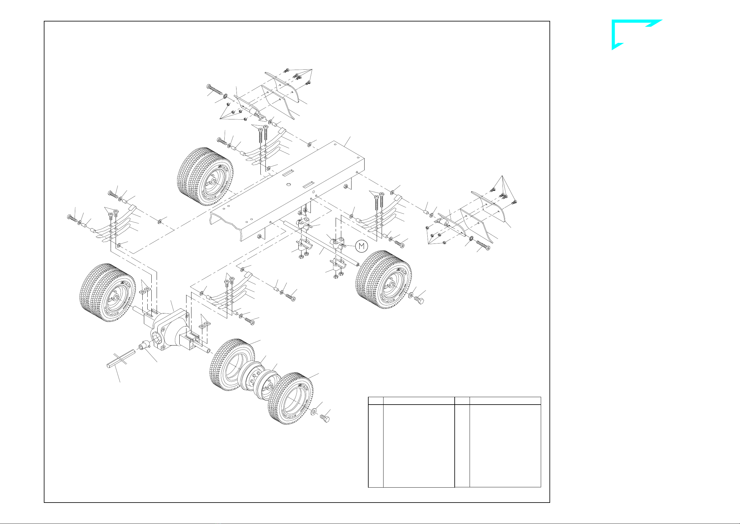
NN cêçåí=~ñäÉ=ëÉÅíáçå=
11.1 Mounting the suspension with front axle
First install the screws 3together with washers 13, bushings 26, and
M3 nuts at the rearward holes in the frame, provided for attaching the
springs. Then attach the open ends of the two long spring leaves 32
at the bushings and use an identical set of parts to screw the closed
ends to the front of the frame 45. One nut 19 each is pressed into the
hexagonal depressions at the steering lever 42. Use two screws 5
and M3 nuts to attach to the long spring leafs, previously mounted,
two medium spring leaves 33 and a short spring leaf 34 along with
two half-axle guards 41, into which the front axle 55 and steering
lever 42 have been inserted. Before tightening down the screws 5
ensure that the spring sets are not under tension and can move
freely.
11.2 Mounting the wheels and steering linkage
First mount the standard tyres 53 on the rims 52. Then use screws
18 and one washer 20 each in front of and behind the axle tube 27
located in the hub to bolt the wheels to the steering lever, using the
nut already inserted. To the outer holes on the steering levers fix two
screws 4along with nuts M3. To this unit add now the track rod 1390
using washers 13 and stop nuts 908; do not tighten the stop nuts but
leave the track rod moveable.
With screws 2fix two ball bolts 29 to the inner holes on the steering
levers for the attachment of the steering rods. To a steering rod 36
add one nut 109, fork head 789 and ball socket 30. The steering rod
has to be bent slightly, depending on the size of the servo unit. After-
wards clip this steering rod for the servo linking to the left-hand ball
bolt. For operation of the blinker switch, add to the right-hand ball
bolt another steering rod 36, equipped with two ball sockets 30. Ad-
just the distance between the ball sockets so that the wheels are in
the straight-ahead position when the lever of the blinker switch is in
its neutral setting.
80-e.DOC / K-Actros Page 8
Front axle section ill. 11
Components attached to the rear frame section ill. 10
Qty.
No. Assembly part
10 ---
Nut M3
2 2
Screw M3 x 8
4 3
Screw M3 x 12
2 4
Screw M3 x 16
4 5
Screw M3 x 20
12 13
Washer 3.2
2 18
Hex head screw
M4 x 25
2 19
Nut M4
4 20
Washer 4.3
4 26
Bushing 4 x 0.5 x 7
2 27
Axle tube
2 29
Ball bolt M3
3 30
Ball socket
Qty.
No. Assembly part
2 32
Spring long, “AF“
4 33
Spring medium, “AF“
2 34
Spring short, “AF“
2 36
Steering rod M2 x 50
4 41
Half-axle guard
2 42
Steering lever
2 52
Rim, chromed
2 53
Standard tyre
“Ecocontrol“
1 55
Front axle
1 109
Nut M2
1 789
Fork head
2 908
Stop nut M3
1 1390
Track rod, flat
Frame
B-44-9
Frame
Note!
The kit contains two
additional red lenses
342 for the US chas-
sis version equipped
with red blinkers.
Inserting the bulbs
Bulb for
brake light
Bulb for blinker
Bulb for rear light
B-44-9
Act
709
709
713
Qty.
No. Assembly part
1 73
Shaft for fifthwheel
1 74
Draw spring
2 341
Blinker lens high, orange
4 342
Lens/rear light high, red
2 655
Adhesive pad,
double-sided
2 709
Lamp cap
1 710
Carrier plate for
support PCB
6 713
Bulb 3V
1 723
PCB support, small
Qty.
No. Assembly part
7 ---
Nut M3
3 1
Screw M3 x 6
2 2
Screw M3 x 8
1 21
Tapping screw 2.2 x 4.5
2 25
Retaining washer 3.2
1 44
Link lever
1 46
Frame tail piece
1 47
Bumper, rear
2 57
Screw M3 x 10
1 71
Standard fifthwheel
1 72
Bar for kingpin

1160
1160
714
15
6
717
6
15
13
13
13 26
3 13 26
33
32
33
32 13
26
13
13
3
13
26
68
70
70
70
70
17
20
17
20
52
52
3
13
26
3
13
26
33
32
13
1
13
66
12
12
32
13
13
26
13
3
1
26
13
3
715
716
33
109
109
717
34
34
4
114
34
64
714
114
4
34
`çãéäÉíÉ=háí==^`qolp=
`çãéäÉíáçå=çÑ=~ëëÉãÄäó=Öêç éë
80-e.DOC / K-Actros Page 9
NO oÉ~ê=~ñäÉ=ëÉÅíáçå=
12.1 Mounting the mud guards
The mud guard support 715 is marked with an "X" and will later be
mounted on the passenger’s side, the mud guard support 716
marked "O" on the driver's side. First attach to these supports the
mud flaps 717 and the mud guards 714 with four screws 114 and
nuts 109 each. Then use screws 6, serrated washers 15, bushings
26, two washers 13 and M3 nuts to attach the supports to the holes
at the rear of the frame.
12.2 Mounting the spring set and axle
Attach the open ends of the two long spring leaves 32 to the bushing
and use a screw 3, bushing 26, washer 13 and M3 nut to screw the
closed end to the frame. Press one each M3 nut into the hexagonal
recess at the lower spring carrier 70. The axle 68 can now be
mounted together with the spring carriers, one medium spring leaf 33
each, a short spring leaf 34 and screws 4.
Ensure that the end of the spring carrier 70 identified with an "M"
is toward the wheel.
The ribbon cable with the two lamp PCBs should be mounted
when attaching the rear axle and the differential!
12.3 Mounting the spring set and differential
First attach the long spring leaves 32 to the frame. Once you have
inserted one square nut 12 each into the grooves at the side of the
differential the springs can be attached with screws 1. The differential
has two cams on the wheel mounts; the grooves in the hubs are
aligned exactly with these cams. The wheels are affixed using
screws 17 (which will cut their own threads) and washers 20. Press
the joint ball 64 into the joint socket at the mounted differential.
In no case should you use an M3 screw more than 6 mm long to
affix the spring set as this would cause binding and damage the
shafts on the differential!
12.4 Mounting the wheels
Once you have mounted the drive axle tyre 1160 on the rims 52 the
wheels are mounted on the shaft, with the wheel nuts facing one an-
other and the chromed rims toward the outside; secure with a washer
20 and a screw 17. The wheels should turn easily but there should
not be too much play.
Rear axle section ill. 12
Qty.
No. Assembly part
12 ---
Nut M3
4 1
Screw M3 x 6
6 3
Screw M3 x 12
4 4
Screw M3 x 16
2 6
Screw M3 x 25
4 12
Square nut M3
16 13
Washer 3.2
2 15
Serrated washer 3.2
4 17
Hex head screw M4 x 8
4 20
Washer 4.3
8 26
Bushing 4 x 0.5 x 7
4 32
Spring long, “AF“
4 33
Spring medium, “AF“
4 34
Spring short, “AF“
Qty.
No. Assembly part
4 52
Rim, grey
4 52
Rim, chromed
1 64
Ball joint
1 66
Standard differential,
mounted
1 68
Rear axle 144mm
4 70
Spring carrier, plastic
8 109
Nut M2
8 114
Screw M2 x 6
2 714
Mud guard
1 715
Mudguard support “X“
1 716
Mudguard support “O“
2 717
Mud flap
8 1160
Drive axle tyre “Ecoforce“
Drive shaft
Frame
B-44-10
(grey)
(chromed) For a better overview the
illustration is showing
an assembly without rear
bumper and fifth-wheel

`çãéäÉíÉ=háí==^`qolp=
`çãéäÉíáçå=çÑ=~ëëÉãÄäó=Öêç éë
64
62
13
13
949
949
1056
1056
54
54
2
60
61
63
59
708
359
2
13
2
58
391
1582
109
1044 653
654
6
1039
1041
1045
653
654
115
1042
2
1043
1039 NP aêáîÉ=ëÉÅíáçå=
13.1 Mounting the motor and gearbox
Use screws 2to bolt the gear cover 59 to the motor 708 (we supply
the white motor pinion 60 (14t.) already mounted to the motor shaft).
Before assembling the gearing lubricate the gears and shafts lightly
with Vaseline. Then clip the joint ball 64 in the gear wheel 62. Lay this
gear wheel, the double pinion 61 with shaft 63 and -not to forget!- the
shim 391 in the gear housing 58 and use screws 2and M3 nuts to
secure the gear housing to the cover. Once assembled, this unit is
inserted from above into the opening in the frame and secured at the
sides with screws 2, washers 13 and M3 nuts. At the same time the
drive shaft 359 is inserted at the joint balls between the gearbox and
the differential.
13.2 Mounting the speed controller
When affixing the speed controller 1582 please ensure that the
ribbon cable with the two lamp PCBs are located between the
frame and the screws used to affix the speed controller (ill. 8).
First mount each of the straight ends of the clamp fittings 54 along
with the tank supports 1056 to the right-hand side of the frame; for this
purpose use screws 949 and nuts M3.
Now set the speed controller into the tank supports. Lay the long ends
of the tank supports and the clamp fittings around the speed control-
ler and fix the clamp fittings from underneath to the screws using
washers 13 and nuts M3.
13.3 Mounting the exhaust unit
The threads in the plastic components are cut by the corresponding
screws; therefore before starting the assembly it is advisable first to
screw down them by approx. 2 mm and afterwards to unscrew them
again.
First press the outer exhaust panel 1040 into the slot on the lower
exhaust half shell 1042 and then mount the exhaust pipe 1043 with
one screw 57 and nut M3 (see small drawing).
Using screws 115 and nuts 109 fix the inner exhaust panel 1039 onto
the frame. Now fit the lower half shell along with the premounted
outer panel into the inner exhaust panel and screw down screws 6
but do not fasten them.
Lay the upper exhaust shield 1045 onto the upper exhaust half shell
1041, so that the narrow edge (approx. 2 mm) lays towards the frame;
connect both parts with screws 653 and nuts 654. For this purpose
use that plastic wrench 656 supplied with this kit. Afterwards slide
this premounted half shell into the inner exhaust panel; with it's slot
set it suitably onto the outer exhaust panel. Once all components fit
correctly, tighten screws
Finally add the front exhaust shield 1044 and fix it with four screws
653.
80-e.DOC / K-Actros Page 10
Drive section ill. 13
Qty.
No. Assembly part
11 ---
Nut M3
9 2
Screw M3 x 8
2 6
Screw M3 x 25
4 13
Washer 3.2
2 54
Clamp fitting,
standard frame
1 57
Screw M3 x 10
1 58
Case for gear 116
1 59
Cap for gear 116
(1)
60
Motor pinion white,
14teeth
1 61
Double pinion
1 62
Gear wheel with
joint socket
1 63
Shaft for gear 116
1 64
Ball joint
2 109
Nut M2
2 115
Screw M2 x 8
1 359
Drive shaft 145mm
8 653
Hex head screw
M1.6 x 4
Qty.
No. Assembly part
1 391
Shim 5 x 10 x 1
4 654
Nut M1.6
1 656
Socket wrench 3.2/ 2.5
1 708
Bühler motor including
14 teeth pinion
2 949
Screw M3 x 35
1 1039
Exhaust panel, inside
1 1040
Exhaust panel, outside
1 1041
Exhaust half shell, top
1 1042
Exhaust half shell,
bottom
1 1043
Exhaust pipe
1 1044
Exhaust shield, front
1 1045
Exhaust shield, top
2 1056
Tank support for
square tank
1 1582
Speed controller,
square tank
B-80-7a
B
-
80
-
7b
Brake light
green/yellow
to the radio receiver
to battery
B-460-2

`çãéäÉíÉ=háí==^`qolp=
`çãéäÉíáçå=çÑ=~ëëÉãÄäó=Öêç éë
629
630
701
210
560
479
1023
1
1
1
12
12
24
24
1026
479
1028
1027
7
397
355
12
217
80-e.DOC / K-Actros Page 11
Mounting the switch panel into the cab ill. 14
Battery plate, side- and front covers ill. 15
NQ jç åíáåÖ=íÜÉ=ëïáíÅÜ=é~åÉä=áåíç=íÜÉ=Å~Ä=
The jacks 701 attached to the switch panel are clipped into the
matching slots in the lower rear panel. The insulating discs, red 629
and black 630, are attached from the outside and secured with the
knurled nuts 560. The black insulating disc serves to identify the jack
with the two black conductors!
When installing the rear panel make sure that the solder lugs of
the jacks do not touch!
NR _~ííÉêó=éä~íÉI=ëáÇÉJ=~åÇ=Ñêçåí=ÅçîÉêë=
15.1 Battery plate
Slide one square nut 12 into each groove on both lower fixing frames
on the side panels. From inside press the battery plate 1023 -
thereby the cut out shows in direction of the dashboard - horizontal
between the side panels. Use screws 1to fix the battery plate under-
neath the fixing frames.
15.2 Mounting the fenders with mud flaps
Slide one square nut 12 into the slot of the lower fixing frame on the
left side panel. Attach the pre-mounted left fender under the cab, so
that the fixing edge of the fender fits above the lower rear panel. Use
two tapping screws 479 and washers 24 to connect from underneath
the following parts: left mud flap 1027, fixing device of the fender and
lower rear panel. The fixing device of the fender has to be secured at
the following points: with one screw 1to the side panel, and with two
countersunk screws 355 and nuts M3 to the front panel. Attach the
right fender with the right mud flap 1028 in the same way.
15.3 Assembly of the front covering
Set the bumper with the lamp units previously added to the front panel
and fix it from inside with two countersunk screws 7. Above the
bumper press the radiator grille 1026 to the front panel and fix it from
inside with four tapping screws 397. Afterwards press the Mercedes
Star 217 into the opening provided for on the radiator grille.
Qty.
No. Assembly part
4 210
Knurled nut M5
2 560
Knurled nut M6
1 629
Insulating disc, red
Qty.
No. Assembly part
1 630
Insulating disc, black
2 701
Jack bush 3.5mm
B-80-9
B-80-8
Qty.
No. Assembly part
4 ---
Nut M3
6 1
Screw M3 x 6
2 7
Countersunk screw
M3 x 6
6 12
Square nut M3
4 24
Washer 2.2
1 217
Mercedes star
4 355
Countersunk screw
M3 x 8
Qty.
No. Assembly part
4 397
Tapping screw 2.2 x 6.5
4 479
Tapping screw 2.2 x 9.5
1 1023
Battery plate ACTROS
1 1026
Radiator grille ACTROS
1 1027
Mud flap -lh- ACTROS
1 1028
Mud flap -rh- ACTROS
Switch panel
to front PCB
to battery
to blinker switch
to rear PCB
to 7
-
pole socket
terminal for roof
to speed controller
to charging cable

`çãéäÉíÉ=háí==^`qolp=
`çãéäÉíáçå=çÑ=~ëëÉãÄäó=Öêç éë
1392
1389
718
655
1032
1034
1033
228
573 574
574
573
729
728
731 727
1
1
632 1
632
NS cáå~ä=~ëëÉãÄäó=
16.1 Attachment of the cab onto the frame
Attach the cab by fixing the front panel onto the frame. Open slots
at the flange on the bottom of the front panel serve for this purpose:
Slide them onto those bushings screwed onto the front frame (see
notes below), and then fix them with two hinge supports 632 and
with screws 1. Thus the cab tilts forwards.
16.2 Mounting the seats
Use screws 1and nuts M3 to attach the seat socket 729 onto the
seat back 728. With two screws 727 fix the U-bow 731 onto the lower
fixing holes of the seat back. Hang the mounted seats into the slots of
the seat rear panel.
16.3 Attachment of battery and roof
From the rear set first the battery 1392 into the cab. The space be-
tween battery and battery plate may serve for the installation of a
Diesel Engine Sound, Art.-No. 193.
As described before, the proper roof is not fixed directly to the cab.
From top slide the rear panel -previously mounted to the roof- be-
tween both side panels; that pigot mounted to the roof serves for se-
curing it. The roof gets locked by turning those door locks you have
added above the doors.
16.4 Attaching the small exterior components
As shown in the illustration add now all stickers you have chosen for
your cab from the decal sheet 1014.
Press the two windscreen wipers 228 and the two front handles 1032
into the holes at the front panel. The sun visor 1389 is attached
above the windshield with two adhesive pads 655. Insert the antenna
718 into the antenna socket after sliding the ball onto the tip of the
antenna.
Finally add the side mirrors. Stick the reflector foil 574 onto the mirrors
573 and press them onto the mirror supports 1033 and 1034. Hang
on the complete mirror to the mirror supports you have already
mounted to the doors.
80-e.DOC / K-Actros Page 12
Final assembly ill. 16
B-80-10a
B-80-10b
Assembly group Roof
Stickers to be
taken off the
decal sheet 1014
Stickers to be
taken off the
decal sheet 1014
Fixing part on
the front panel
flange of the fully assembled cab
Qty.
No.
Assembly part
2 729
Socket, bucket seat
2 731
U-bow, bucket seat
1 1014
Decal sheet ACTROS
2 1032
Front handle ACTROS
1 1033
Mirror support -lh-
ACTROS
1 1034
Mirror support -rh-
ACTROS
1 1389
Sun visor ACTROS
1 1392
12V battery ACTROS
Qty.
No.
Assembly part
6 1
Screw M3 x 6
1 228
Windscreen wiper -lh-
1 228
Windscreen wiper -rh-
2 573
Mirror black
2 574
Reflector foil
2 632
Scharnierhalter
2 655
Klebepad, doppelseitig
1 718
Antenna with ball
4 727
Countersunk tapping
screw 2.2 x 6.5
2 728
Back, bucket seat

`çãéäÉíÉ=háí==^`qolp=
`çãéäÉíáçå=çÑ=~ëëÉãÄäó=Öêç éë
NT qÜÉ=ÉäÉÅíêáÅ~ä=ëóëíÉã=
The wiring diagram shows the cable connections for the individual
electrical components.
17.1 Mounting the switching panel and lamp PCBs
The switch panel is inserted into the seat rear panel of the cab. First
connect the bulbs and cables and then clip the lamp PCBs in place
at the front and rear in the supports provided for this purpose.
17.2 Information on the bulbs, troubleshooting
All the bulbs are 3-volt bulbs connected in series. This means that
the conductors are not each connected to the supply voltage, as in
an automobile. Instead, the ends are joined one to another to form a
chain and the ends of the chain are attached to the power supply.
Consequently just a single defective bulb will interrupt the entire cir-
cuit and none of the lamps in the chain will light. The best way to lo-
cate the defective bulb is to use a cable to bypass each of the bulbs
in the series, one after the other. When you bypass the defective
bulb, the rest in the chain will light. The reason for using a series cir-
cuit, which may appear to be complicated, is the low power consump-
tion. 3-volt bulbs use far less power than 12-volt bulbs in relation to
their brightness. The power consumed by a chain of up to five 3-volt
bulbs is just 0.1 A in the series connection which we use; 12-volt
bulbs, by comparison, would draw 0.3 A.
17.3 Wiring the roof lamps
Connect the red/black cable of the switch panel to the 7-pole socket
terminal provided for the roof. Then connect the bulb wires as well as
the resistor to the 7-pole pin terminal underneath the roof (see also il-
lustration 4.5).
17.4 Wiring at the rear lamp PCB
(tail and brake lights, rear blinkers)
The red/black/yellow cable exiting the switch panel for the rear lamps
is routed under the frame and to the rear and connected to the PCB
- marked on the bottom with „H“ for rear - as shown in the illustration.
The green/yellow brake light cable coming from the speed controller
is also to be connected at this PCB. Once the bulb leads have been
attached, the PCB is clipped in place at the support which was previ-
ously affixed with adhesive pads.
Explanation: The green/yellow brake light cable connects the brake
light bulbs to ground when the vehicle is at a standstill. This circuitry
incorporates an element which limits the current to 750 mA and will
disable the circuit in case of an overload or short. Switching off the
supply voltage for about one second will reset this element, provided
that the reason for the malfunction has been corrected.
17.5 Wiring at the front lamp PCB
(headlamps, front blinkers)
The green/yellow/grey cable serving the lamps at the front also exits
from the switch panel and is routed below the frame and to the front
in exactly the same fashion. After connecting to the PCB - marked
on the bottom with „V“ for front - and connecting the bulb leads, the
lamp PCB is clipped in place in the support previously mounted.
17.6 Wiring the blinker switch
The green/brown/white cable for the blinker switch terminates in a
clamp-type connector (see therefore ill. 17a on page 14). This con-
nector is attached to the blinker switch (if the direction of travel does
not correspond to the blinking, please rotate it through 180°),
mounted beneath the steering servo, already illustrated in ill. 9.
80-e.DOC / K-Actros Page 13
Wiring diagram of the electrical equipment ill. 17
Supplied with the kit:
No. Assembly part
568
Antenna socket
708
Drive motor
929
Clamp-type connector
1000
7-pole pin terminal
1001
7-pole socket terminal
1038
Resistor 80.6 Ω/ 0.5W
1392
12V battery ACTROS,
1582
Speed controller, square tank
---
Blinker switch
---
Charging cable with AMP-plug
---
Set of circuit boards f. complete
chassis with lamp PCBs
---
Switch panel with jack bushes
Not supplied with the kit:
RC receiver
Steering servo
Servo connecting cable
Cable for receiver voltage
7-pole
socket
terminal
for roof
to the engine noise
(not incl. in the kit)
7-pole pin
terminal
for roof
Roof
lamps
80.6
Ω
Blinker switch
white
brown
green
black
red
Brake light
yellow/green
Motor
yellow
yellow
yellow
yellow
red
black
Antenna socket
brown/red/orange
Clamp
type
connector
red
black
red
black
yellow
green
yellow
grey Head lamps -lh-/-rh-
RECEIVER
(not incl. in the kit)
to the battery box of the
remote control system
or alternative to the
switch panel (ill. 20)
Speed controller
Antenna cable
black
red
Blinker -lh-
Blinker -rh-
12V Battery ACTROS
Switch panel
Charging
cable
black
red
blue
Jack bush
Jack bush
Knurled nut
Disc red
Knurled nut
Disc black
grey
green
yellow
Front lamp PCB
Set of circuit boards
for chassis
Blinker -rh-
Blinker -lh-
Rear lamp PCB
black
black
red
yellow
Brake lights
Rear lights
yellow/green
red
black
red
red
Steering
servo
(not incl.
in the kit)
Control LED
V
H
Cable for receiver voltage
(not incl. in the kit)
B-80-12

`çãéäÉíÉ=háí==^`qolp=
`çãéäÉíáçå=çÑ=~ëëÉãÄäó=Öêç éë
Blinking LED
Hazard warning
Lights
Receiver
Power / Charging
Main switch
OFF
ON
red
blue
black = minus pole (-)
red = plus pole (+)
Charging cable
from the
switch panel Switch panel Plug for the connection
to receiver battery
(+) red (5V)
(-) black
80-e.DOC / K-Actros Page 14
1. Put in the servo
connecting cable in
the matching colour
sequence, the wire ends
protruding about 10 mm.
3. Cut off the
wire ends and
insulate wires.
2. Carefully squeeze the
clamp-type connector
using a pair of pliers or
better, a small vice, until
the locks at the sides
snick audibly into place.
B-44-15
17.7 Connecting the speed controller
Connect the AMP socket with the yellow cables to the corresponding
AMP plug at the drive motor, and the AMP plug with the red/black
cables to the AMP socket at the switch panel.
The connection of the green/yellow brake light cable has already
been described in Section 17.4. The signal "brake light" is switched
by minus line, and it is time-triggered: As soon as one changes the
position of the control lever from either "forward" or from "reverse" to
the neutral position (switched-off), the brake light starts lighting for
approx. eight seconds. But as soon as the travelling operation is
started again, the brake light stops automatically its blinking, even
before having finished these eight seconds.
Attach the connecting socket with the brown/red/orange cable to one
of the receiver terminals. If the socket doesn't match the receiver,
you will need to add an adapter cable (not making part of this kit).
17.8 Starting the electrical system (see switches, ill.17b)
The electrical system is put into operation by turning on the main
switch; the LED blinks. Then the transmitter and receiver are switched
on, in this order. (Always switch off the receiver first and then the
transmitter!) If a speed controller has been installed, the brake lights
will go on. If the light switch is on, the headlamps, the roof lamps and
the tail lamps will light.
NU qÜÉ=ëéÉÉÇ=ÅçåíêçääÉê=
The WEDICO speed controller is matched to the WEDICO-Bühler
motor. The electronics are permanently installed in a tank housing,
which should never be opened! Never apply force as this could
damage the speed controller and nullify any and all guarantee enti-
tlements. Prior to its supply, each speed controller is individually
tested and provided with a basic programming. In your particular
case, probably this general basic programming may not be the opti-
mal for the type of RC equipment you are using, but you of course
may change it (for further details please refer to the section 18.2
"programming").
18.1 Starting the speed controller
Switch the electrics on by the following sequence: start by the main
switch of the Electr. System, then switch on the transmitter, and finally
the receiver; keep your eye on the control LED. Before you make the
motor starts working remote-controlled, it is the speed controller which
has first to detect the programmed neutral position; this position sits
approx. in the centre on the control lever of your transmitter unit. Once
the speed controller has correctly detected said position, as a con-
firmation the control LED starts blinking for a ten times term. Only
then one may consider the speed controller as in state of readiness;
and now the motor power can be controlled for both senses of direc-
tion via the control lever.
18.2 How to programme the speed controller
Continue paying your attention to the control LED. For the correct ad-
justment of the control lever on the transmitter, set the shift controller
in neutral position; slide then the control lever into that position at
which you wish the motor to be "off". As a confirmation, lightly press
the programming key "4" on the speed controller (refer to next para-
graph). Do not move the control lever on the transmitter. Now, the
speed controller detects the neutral position, and the control LED
starts its ten times blinking.
Immediately after the blinking activity has started, slide the control
lever into the position for maximum "forward" speed; secure the lever
at this point. Do not move it. Even after the 10th blinking, the control
LED remains dark. As soon as the transmitter of your RC equipment
has detected the pulse corresponding to the maximum speed, the
control LED starts blinking again for a ten times term.
Immediately after the start of this blinking activity move the control
lever from the position "forward" directly to the position provided for
maximum "reverse" speed; secure the lever at this position. Again,
after the 10th blinking the control LED remains dark. Once the
transmitter of the RC unit has detected that pulse responsible for the
maximum speed, the control LED starts blinking again.
This signifies that the programming procedure of the speed controller
has been completed. The transmitter of the RC unit has successfully
detected the pulse coming from the speed controller, and now the
complete system is ready to operate.
If an error has been made during the programming procedure, the
system will not accept the new figures. In this case switch your Elec-
trical System off just for a short moment, and then switch it on again;
this procedure will re-activate the previous version of the program-
ming you have chosen for your speed controller. At this stage you
may start again any new programming.
18.3 Options for adjusting the speed controller
The holes at the rear tank cover are identified by numbers and serve
for the following types of adjustments, as there are:
•to "3": By a potentiometer, adjustment of the maximum motor speed
from 50 to 100% for the 1st direction (either forward or reverse, see
below),
•to "4": By key initiating the programming procedure,
•to "5": By potentiometer, adjustment of the maximum motor speed
from 50 to 100% for the 2nd direction (either forward or reverse, see
below).
It is by testing only that you find out which of both holes, either "3" or
"5", is responsible for the maximum motor speed of the direction
“forward” resp. the direction “REVERSE”.
Standard values on the speed controller are adjusted by manufactur-
ers. For any alteration of adjustment use a small screwdriver. Be
careful and don't apply any force!
18.4 Troubleshooting
No blinking activity on the
speed controller after hav-
ing put into operation
The position of the shifting lever
provided for the adjustments does
not correspond to the position of the
programming procedure. Make sure
the shifting lever has been set to neu-
tral position!
Motor does not react at all
Inadequate wire connections;
receiver voltage below 3 V;
main NiCads too low (below 8 V)
NV `Ü~êÖáåÖ=íÜÉ=ÇêáîÉ=Ä~ííÉêó=
For charging the drive battery connect as follows:
•the AMP-plug of the charging cable to that AMP-socket with the
blue/red cable of the cab's switch panel,
•the banana plugs of the charging cable to a charging unit.
Warning: Ensure that the banana plugs for the charging cable do
not touch while the charging cable is connected to the switch
panel.
At normal discharge levels it will take about 12 to 14 hours to re-
charge the battery (at 150 mA). Quick charging should be used only
in exceptional cases at a maximum of 1.5 A for one hour.
OM qÜÉ=êÉãçíÉ=Åçåíêçä=ëóëíÉã=
To operate the speed controller and the steering servo an inexpensive
2/4 channel system will be sufficient. Should you intend installing
additional electrical accessories, such as e.g. Diesel Engine Sound,
Art.-No. 193, for an RC equipment we would recommend a 2/4 chan-
nel unit, offering the installation of retrofit sets for the operation of
switching functions. Please ask your dealer for advice. Follow the in-
structions provided by the RC system manufacturer when installing
the receiver unit.
Should you don't wish the receiver voltage of your radio unit being
supplied via an independent battery, you may connect it to your 12V
truck battery. For this purpose you have to solder the wires of the re-
ceiver battery onto the switch panel (see ill. 20).
Note: By the installed voltage regulator (as a series fitting) the bat-
tery voltage of 12V on the switch panel is now automatically being
reduced to 5 volts.
ON p ééäÉãÉåí~êó=áåÑçêã~íáçå=
Attention: This special electrical equipment making part of our pro-
duction line "Complete Kits" will not fit any other electrical accessory
offered within the range of WEDICO System-Kits.
Should you once wish to extend your "Complete Kit" by
one or the
other electric accessory you will have to exchange this electrical sys-
tem. WEDICO offers you the following Electrical Systems:
•Art.-No. 783: The information to the semi-
trailer is transmitted via a
multi-frequency system. When adding an Infrared System (Art.-
Nr.
790 as transmitter, and Art.-
No. 791 as receiver), you may drive
your prime mover with any of a semi-trailer -
it does not depend on
the type of Electrical System your truck is equipped with.
•Art.-No. 796: The information is serially tra
nsmitted via one data
line only inside the prime mover. The information to the semi-
trailer
is transmitted via an Infrared Diode (transmitter).
Except these electrical components, all other accessories (for stan-
dard chassis) being offered within our programme WEDICO System-
Kits will fit your truck and/or semi-trailer and may be installed.
Switches of the switch panel ill. 17b
Attachment of the clamp-type connector ill. 17a
Charging the batteries ill. 19
Solder points for the connection of 5V receiver voltage ill. 20
At electrical connections, please
make sure that soldering points
are clean and plug connectors
are properly cramped!
Loose plugs and loosely twisted
wire connections cause faults
which are often hardly to locate.

`çãéäÉíÉ=háí==^`qolp=
`çãéäÉíáçå=çÑ=~ëëÉãÄäó=Öêç éë
80-e.DOC / K-Actros Page 15
OO=dÉåÉê~ä=é~êíë=äáëí=
For gaining an easier overview of all single components and
their necessary quantity for the correct assembly of this model,
on the left side of this page you find a complete list including
each single item. For reasons of packaging some of the small
parts are packed in a higher number of pieces than necessary.
On the left side you find the quantity mentioned for each part.
Next to this column you find the numbers of the assembly parts
and their terms, followed by the EDP-numbers to be used
when re-ordering one or the other item.
Complete list of parts necessary for the assembly (please use EDP-number when ordering spare parts)
Qty.
No. Assembly part EDP-
No.
1 1017
Side panel -lh-, ACTROS
white ................................
..............
27338
blue................................
................
27340
yellow................................
.............
27342
1 1018
Side panel -rh-, ACTROS
white ................................
..............
27330
blue................................
................
27332
yellow................................
.............
27334
1 1019
Windscreen ACTROS
......................
27072
1 1020
Fixing plate for front -lh-
......................
27286
1 1021
Fixing plate for front -rh-
.....................
27288
1 1022
Fixing angle for side panels
................
27278
1 1023
Battery plate ACTROS
.....................
27266
2 1025
Stopping device for cab lock
.............
27262
1 1026
Radiator grille ACTROS
...................
27038
1 1027
Mud flap -lh- ACTROS
.....................
27034
1 1028
Mud flap -rh- ACTROS
.....................
27036
1 1029
Cab locking device ACTROS
...........
27256
1 1030
Cab base ACTROS
..........................
27258
2 1032
Front handle ACTROS
.....................
27070
1 1033
Mirror support -lh- ACTROS
.............
27272
1 1034
Mirror support -rh- ACTROS
.............
27274
1 1037
Reflector foil................................
......
27462
1 1038
Resistor for roof lamps,
80.6 Ohm, 0.5 W
............................
25868
1 1039
Exhaust panel, inside
................................
27094
1 1040
Exhaust panel, outside
................................
27096
1 1041
Exhaust half shell, top
................................
27098
1 1042
Exhaust half shell, bottom
................................
27100
1 1043
Exhaust pipe................................
................................
27250
1 1044
Exhaust shield, front
................................
27252
1 1045
Exhaust shield, top
................................
27254
3 1046
Bolt with thread
................................
27412
2 1056
Tank support for square tank
................................
27404
8 1160
Drive axle tyre “Ecoforce“
................................
28172
2 1385
Threaded bushing 18mm
................................
28676
1 1386
Roof, Complete Kit ACTROS “C“
white ................................
..............
29322
blue................................
................
29324
yellow................................
.............
29326
1 1387
Rear panel, bottom
Complete Kit ACTROS “C“
white ................................
..............
29328
blue................................
................
29330
yellow................................
.............
29332
1 1388
Frame ACTROS, 432mm
................................
29316
1 1389
Sun visor ACTROS
................................
27414
1 1390
Track rod, flat, standard
................................
29312
1 1392
Drive battery ACTROS 12V
................................
27442
1 1582
Speed controller, square tank
................................
29762
1 ---
Sticker for switch
................................
20558
1 ---
Charging cable with AMP-plug
................................
25946
1 ---
Switch panel with jack bushes
................................
26068
1 ---
Set of circuit boards
for complete chassis
................................
26072
Qty.
No. Assembly part EDP-
No.
1 929
Clamp-type connector, 3-pole
................................
21772
2 949
Screw M3 x 35
................................
21844
1 968
Inside door panel -lh-
........................
27042
1 969
Inside door panel -rh-
........................
27044
2 970
Support 2, door hinge
.......................
27064
4 971
Door hinge 2 ................................
....
27054
4 972
Door hinge 3 ................................
....
27056
2 973
Door hinge 1 ................................
....
27052
2 974
Door hinge 4 ................................
....
27058
4 975
Support 1, door hinge
.......................
27060
1 976
Door -lh-, ACTROS
white................................
..............
27354
blue................................
................
27356
yellow................................
.............
27358
1 977
Door -rh-, ACTROS
white................................
..............
27346
blue................................
................
27348
yellow................................
.............
27350
1 978
Door trim -lh-................................
.....
27046
1 979
Door trim -rh-................................
.....
27048
2 980
Door lock................................
...........
27050
2 981
Door window................................
.....
27276
1 982
Fender with entry, -lh-
.......................
27014
1 983
Fender with entry, -rh-
.......................
27016
1 984
Fixing plate for fender, -lh-
................
27074
1 985
Fixing plate for fender, -rh-
................
27076
1 986
Top stepboard, -lh-
............................
27080
1 987
Top stepboard, -rh-
...........................
27082
1 988
Centre stepboard, -lh-
.......................
27084
1 989
Centre stepboard, -rh-
.......................
27086
1 990
Bottom stepboard, -lh-
.......................
27088
1 991
Bottom stepboard, -rh-
......................
27090
1 993
Rear panel, top, ACTROS
white................................
..............
27366
blue................................
................
27368
yellow................................
.............
27370
1 994
Locking sheet for roof, -lh-
................
27292
1 995
Locking sheet for roof, -rh-
................
27294
1 996
Guide sheet for roof
..........................
27290
1 997
Lens for roof lamp, -lh- ACTROS
.......
27282
1 998
Lens for roof lamp, -rh- ACTROS
.......
27284
1 1000
7-pole pin terminal
.............................
27386
1 1001
7-pole socket terminal
.......................
27388
1 1002
Air filter, outside part ACTROS
........
27066
1 1003
Air filter, inside part ACTROS
...........
27062
1 1004
Air filter, side part ACTROS
.............
27068
1 1005
Bumper ACTROS
............................
27012
1 1006
Headlight housing -lh- ACTROS
........
27018
1 1007
Headlight housing -rh-. ACTROS
........
27020
1 1008
Blinker lens outside -lh- ACTROS
.......
27026
1 1009
Blinker lens outside -rh- ACTROS
......
27028
1 1010
Blinker lens -lh- ACTROS
..................
27030
1 1011
Blinker lens -rh- ACTROS
.................
27032
1 1014
Decal sheet ACTROS
......................
27296
1 1015
Dashboard ACTROS
........................
27040
1 1016
Rear panel, top, ACTROS
white................................
..............
27322
blue................................
................
27324
yellow................................
.............
27326
Qty.
No. Assembly part EDP-
No.
2 176
Coil spring for lever
................................
20260
4 210
Knurled nut M5
................................
20440
1 217
Mercedes star
................................
21956
1 222
Seat rear panel
................................
21962
1 228
Windscreen wiper -lh-
................................
21972
1 228
Windscreen wiper -rh-
................................
21974
2 341
Blinker lens high, orange
................................
20304
4 342
Lens/rear light high, red
................................
20308
6 355
Countersunk screw M3 x 8
...............
20030
1 359
Drive shaft 145mm
................................
20716
1 391
Shim 5 x 10 x 1
................................
23346
4 397
Tapping screw 2.2 x 6.5
................................
23690
4 470
Mirror hinge, bottom
................................
24292
4 479
Tapping screw 2.2 x 9.5
...................
24868
1 498
Switch dashboard
................................
24714
2 560
Knurled nut M6
................................
---
11 564
Countersunk
tapping screw 2.2 x 4.5
................................
25072
1 568
Antenna socket, complete.
................................
20430
2 573
Mirror black................................
................................
20398
2 574
Mirror foil................................
................................
20366
2 611
Door handle, MAN
................................
25444
2 624
Headlight lens, MAN
................................
25338
1 629
Insulating disc, red
................................
26230
1 630
Insulating disc, black
................................
26232
2 632
Hinge support
................................
25704
8 653
Hex head screw M1.6 x 4
................................
24614
4 654
Nut M1.6................................
................................
23734
8 655
Adhesive pad, double-sided
................................
20410
1 656
Socket wrench 3.2 / 2.5
................................
24800
2 701
Jack bush 3.5mm
................................
26076
2 707
Horn................................
................................
20350
1 708
Bühler motor incl. 14 teeth pinion
................................
22298
2 709
Lamp cap................................
................................
20264
1 710
Carrier plate for support PCB
................................
23334
12 713
Bulb 3V................................
................................
20310
2 714
Mud guard ................................
................................
21272
1 715
Mudguard support “X“
................................
21275
1 716
Mudguard support “O““
................................
21274
2 717
Mud flap................................
................................
24074
1 718
Antenna with ball
................................
20432
1 719
Cover for blinker switch
................................
24920
1 720
Base for blinker switch
................................
24916
2 721
Spring, single bent
................................
25066
1 722
Spring, double bent
................................
25068
2 723
PCB support, small
................................
21530
1 724
Lever for blinker switch
................................
24918
8 727
Countersunk tapp. screw 2.2 x 6.5
.......
26252
2 728
Back, bucket seat
.............................
26032
2 729
Socket, bucket seat
..........................
26030
2 731
U-bow, bucket seat
...........................
26036
2 741
Screw M2 x 4
................................
26236
5 742
Screw M2 x 5
................................
26238
1 760
Servo angle 1, small
................................
26122
1 789
Fork head ................................
................................
20400
14 827
Pin for door hinge
.............................
25980
2 907
Countersunk screw M2 x 8
..............
26688
2 908
Stop nut M3................................
................................
30568
2 926
Countersunk screw M2 x 5
..............
25224
Qty.
No. Assembly part EDP-
No.
64 ---
Nut M3
................................
................................
20040
41 1
Screw M3 x 6................................
...............................
20016
25 2
Screw M3 x 8................................
...............................
20018
10 3
Screw M3 x 12
................................
20022
10 4
Screw M3 x 16
................................
20024
4 5
Screw M3 x 20
................................
20224
4 6
Screw M3 x 25
................................
20026
2 7
Countersunk screw M3 x 6
..............
20028
24 12
Square nut M3
................................
20044
45 13
Washer 3.2................................
................................
20046
6 14
Spring washer 3.2
................................
20056
6 15
Serrated washer 3.2
................................
20054
4 17
Hex head screw M4 x 8
................................
20036
2 18
Hex head screw M4 x 25
................................
20038
2 19
Nut M4................................
................................
20042
8 20
Washer 4.3................................
................................
20048
3 21
Tapping screw 2.2 x 4.5
................................
20052
6 24
Washer 2.2................................
................................
21210
2 25
Retaining washer 3.2
................................
20058
16 26
Bushing 4 x 0.5 x 7
................................
20088
2 27
Axle tube ................................
................................
20150
2 29
Ball bolt M3 ................................
................................
20170
3 30
Ball socket ................................
................................
20172
6 32
Spring long, “AF“
................................
20132
8 33
Spring medium, “AF“
................................
20134
6 34
Spring short, “AF“
................................
20136
2 36
Threaded rod M2 x 50
................................
20268
4 41
Half-axle guard
................................
20144
2 42
Steering lever
................................
20146
1 44
Link lever ................................
................................
20148
1 46
Frame tail piece
................................
20002
1 47
Bumper, rear ................................
...............................
20006
4 52
Rim, grey ................................
................................
20128
6 52
Rim, chromed
................................
20420
2 53
Standard tyre “Ecocontrol“
................................
28840
2 54
Clamp fitting, standard frame
................................
20124
1 55
Front axle ................................
................................
20142
1 56
Steering wheel
................................
20156
5 57
Screw M3 x 10
................................
20020
1 58
Case for gear 116
................................
20318
1 59
Cap for gear 116
................................
20320
(1)
60
Motor pinion, white, 14teeth
................................
20300
1 61
Double pinion for gear 116
................................
20324
1 62
Gear wheel with joint socket
................................
20326
1 63
Shaft 5 x 24 for gear 116
................................
20330
2 64
Ball joint ................................
................................
20328
1 66
Standard differential, mounted
................................
21234
1 68
Rear axle 144mm
................................
20126
4 70
Spring carrier, plastic
................................
20138
1 71
Standard fifthwheel
................................
20008
1 72
Bar for kingpin
................................
20010
1 73
Shaft for fifthwheel
................................
20012
1 74
Draw spring................................
................................
20462
2 75
Door handle ................................
................................
20084
2 76
Door lock................................
................................
20086
25 109
Nut M2................................
................................
21208
4 111
Self-cutting screw M3 x 8
................................
20223
18 114
Screw M2 x 6................................
...............................
21268
2 115
Screw M2 x 8................................
...............................
21269
This manual suits for next models
3
Other WEDICO Motorized Toy Car manuals