manuals.online logo
Brands
  1. Home
  2. •
  3. Brands
  4. •
  5. Weider
  6. •
  7. Home Gym
  8. •
  9. Weider Pro 8900 User manual

Weider Pro 8900 User manual

Other manuals for Pro 8900

1

This manual suits for next models

1

Other Weider Home Gym manuals

Weider 831.153972 User manual

Weider

Weider 831.153972 User manual

Weider WEMC10161 User manual

Weider

Weider WEMC10161 User manual

Weider WEBE09310 User manual

Weider

Weider WEBE09310 User manual

Weider 184 Bench User manual

Weider

Weider 184 Bench User manual

Weider 230 Bench User manual

Weider

Weider 230 Bench User manual

Weider Victory 527 User manual

Weider

Weider Victory 527 User manual

Weider WESY85104 User manual

Weider

Weider WESY85104 User manual

Weider 8520 User manual

Weider

Weider 8520 User manual

Weider WESY68632 User manual

Weider

Weider WESY68632 User manual

Weider 9150 User manual

Weider

Weider 9150 User manual

Weider C420 User manual

Weider

Weider C420 User manual

Weider 8950 Quick start guide

Weider

Weider 8950 Quick start guide

Weider WESY78732 User manual

Weider

Weider WESY78732 User manual

Weider 9900i User manual

Weider

Weider 9900i User manual

Weider Muscle 130 For Hermans Bench User manual

Weider

Weider Muscle 130 For Hermans Bench User manual

Weider Pro 202 831.150260 User manual

Weider

Weider Pro 202 831.150260 User manual

Weider 831.150720 User manual

Weider

Weider 831.150720 User manual

Weider Body Works Pro 2.0 Bench Manual

Weider

Weider Body Works Pro 2.0 Bench Manual

Weider Pro 2250 User manual

Weider

Weider Pro 2250 User manual

Weider Pro 120 Bench User manual

Weider

Weider Pro 120 Bench User manual

Weider 190 Rx Bench User manual

Weider

Weider 190 Rx Bench User manual

Weider MEDALLION M125 User manual

Weider

Weider MEDALLION M125 User manual

Weider XP 800 WESY75742 User manual

Weider

Weider XP 800 WESY75742 User manual

Weider 244 Bench User guide

Weider

Weider 244 Bench User guide

Popular Home Gym manuals by other brands

T.D.S. 3501 Assembly instructions

T.D.S.

T.D.S. 3501 Assembly instructions

Body Solid EXM1950 Assembly instructions

Body Solid

Body Solid EXM1950 Assembly instructions

Horizon Fitness OXFORD 6 manual

Horizon Fitness

Horizon Fitness OXFORD 6 manual

Energetics Multi Trainer 5.1 owner's manual

Energetics

Energetics Multi Trainer 5.1 owner's manual

Precor Discovery Series owner's manual

Precor

Precor Discovery Series owner's manual

Matrix MG-PL Series Service manual

Matrix

Matrix MG-PL Series Service manual

Reebok Tbr2i Manuale d'istruzioni

Reebok

Reebok Tbr2i Manuale d'istruzioni

Pure Fitness 8526HE owner's manual

Pure Fitness

Pure Fitness 8526HE owner's manual

Bowflex Sport 001-6961 Assembly instructions

Bowflex

Bowflex Sport 001-6961 Assembly instructions

NordicTrack E8200 Competition Bench Bedienungsanleitung

NordicTrack

NordicTrack E8200 Competition Bench Bedienungsanleitung

Insportline RW600 user manual

Insportline

Insportline RW600 user manual

Body Solid GHYP-345 owner's manual

Body Solid

Body Solid GHYP-345 owner's manual

Evo TAHOE 5105 user manual

Evo

Evo TAHOE 5105 user manual

ParaBody 40 Assembly instructions

ParaBody

ParaBody 40 Assembly instructions

JLL Ventus Pro Air Power instruction manual

JLL

JLL Ventus Pro Air Power instruction manual

Trojan Colorado 370 user manual

Trojan

Trojan Colorado 370 user manual

Tunturi R25 owner's manual

Tunturi

Tunturi R25 owner's manual

Deltech Fitness DF102 Assembly instructions

Deltech Fitness

Deltech Fitness DF102 Assembly instructions

manuals.online logo
manuals.online logoBrands
  • About & Mission
  • Contact us
  • Privacy Policy
  • Terms and Conditions

Copyright 2025 Manuals.Online. All Rights Reserved.

WEIGHT SYSTEM EXERCISER
Userʼs Manual
CAUTION
Read all precautions and instruc-
tions in this manual before using
this equipment. Keep this manual
for future reference.
Model No. 831.14923.1
Serial No.
Write the serial number in the
space above for reference.
• Assembly
• Operation
• Maintenance
• Part ist and Drawing
Sears, Roebuck and Co.
Hoffman Estates, I 60179
Serial Number
Decal
2
WARNING DECA P ACEMENT
TAB E OF CONTENTS
WARNINGDECA P ACEMENT ..............................................................2
IMPORTANTPRECAUTIONS ................................................................3
BEFOREYOUBEGIN ......................................................................4
PARTIDENTIFICATIONCHART ..............................................................5
ASSEMB Y ...............................................................................7
ADJUSTMENT ...........................................................................34
WEIGHTRESISTANCECHART..............................................................37
CAB EDIAGRAM.........................................................................38
MAINTENANCE ..........................................................................39
EXERCISEGUIDE INES ...................................................................40
PART IST ..............................................................................43
EXP ODEDDRAWING ....................................................................45
ORDERINGREP ACEMENTPARTS ..................................................BackCover
90-DAYFU WARRANTY ..........................................................BackCover
This drawing shows the location(s)
of the warning decal(s). If a decal
is missing or illegible, call
1-877-992-5999 and request a
free replacement decal. Apply
the decal in the location shown.
Note: The decal(s) may not be
shown at actual size.
3
IMPORTANT PRECAUTIONS
1. It is the responsibility of the owner to ensure
that all users of the weight system are ade-
quately informed of all precautions.
2. Before beginning any exercise program,
consult your physician. This is especially
important for persons over age 35 or per-
sons with pre-existing health problems.
3. Use the weight system only as described in
this manual.
4. The weight system is intended for home use
only. Do not use the weight system in a com-
mercial, rental, or institutional setting.
5. Keep the weight system indoors, away from
moisture and dust. Do not put the weight
system in a garage or covered patio, or near
water.
6. Place the weight system on a level surface,
with a mat beneath it to protect the floor or
carpet. Make sure that there is enough clear-
ance around the weight system to mount,
dismount, and use the weight system.
7. Inspect and properly tighten all parts regu-
larly. Replace any worn parts immediately.
8. Keep children under age 12 and pets away
from the weight system at all times.
9. The weight system should not be used by
persons weighing more than 300 lbs.
(136 kg).
10. Wear appropriate exercise clothes while
exercising; do not wear loose clothes that
could become caught on the weight system.
Always wear athletic shoes for foot
protection.
11. Keep hands and feet away from moving
parts.
12. Always secure the weight stack with the lock
pin and the lock after exercising to prevent
unauthorized use of the weight system (see
OCKING THE WEIGHT STACK on page 36).
13. Make sure that the cables remain on the pul-
leys at all times. If the cables bind while you
are exercising, stop immediately and make
sure that the cables are on the pulleys.
14. Always stand on the foot plate when per-
forming an exercise that could cause the
weight system to tip.
15. Never release the arms, leg lever, lat bar,
handle, ankle strap, or double strap while
weights are raised. The weights will fall with
great force.
16. Always disconnect the lat bar from the
weight system when performing an exercise
that does not require the lat bar.
17. Over exercising may result in serious injury
or death. If you feel faint or if you experience
pain while exercising, stop immediately and
cool down.
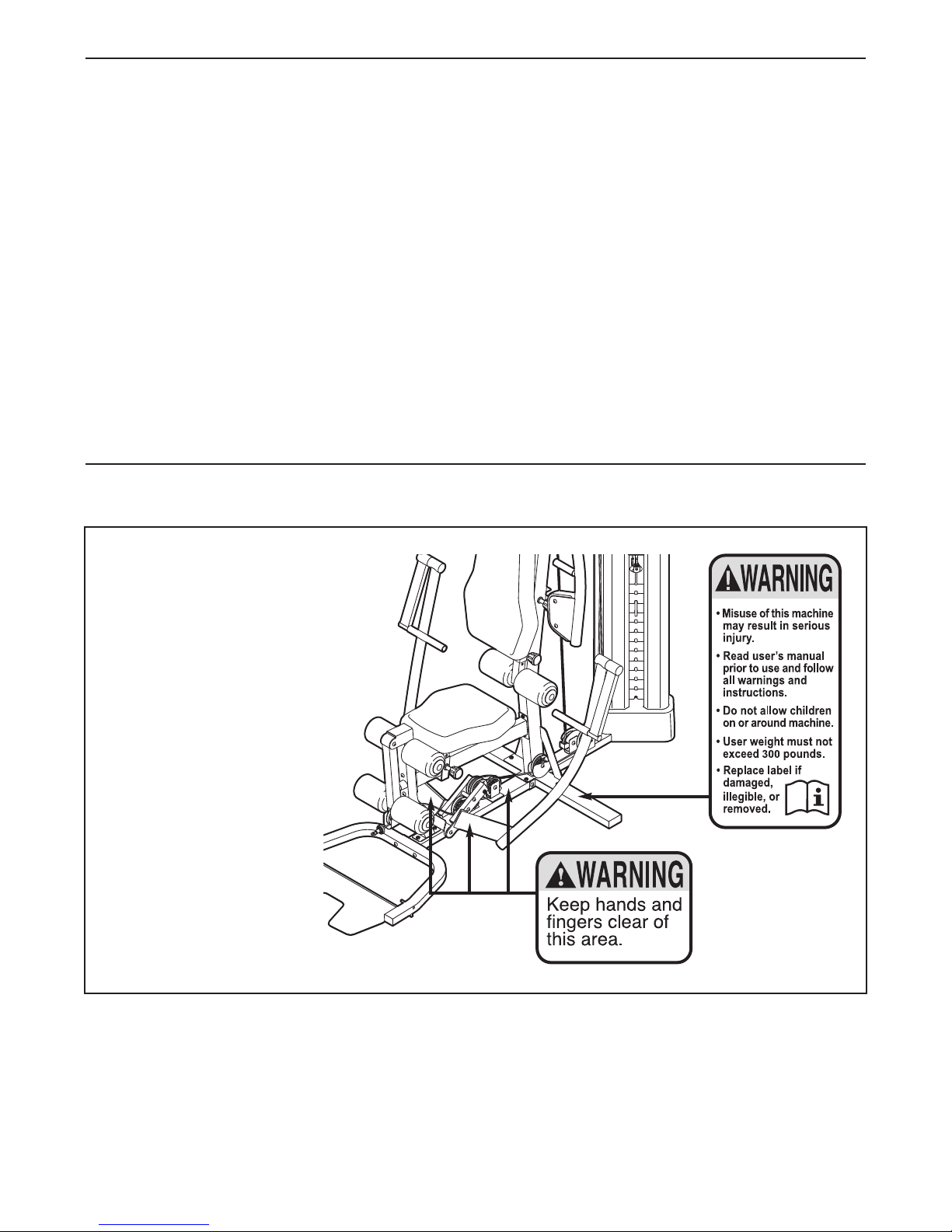
WARNING: To reduce the risk of serious injury, read all important precautions and
instructions in this manual and all warnings on your weight system before using your weight sys-
tem. Sears assumes no responsibility for personal injury or property damage sustained by or
through the use of this product.
4
Assembled Dimensions:
Height: 6 ft. 11 in. (211 cm)
Width: 4 ft. 1 in. (124 cm)
Depth: 7 ft. 1 in. (216 cm)
Shroud
High Pulley Station
ow Pulley Station
Ankle Strap
Double Strap
Right Side
eft Side
Backrest
Ab Station
at Bar
Weight
Weight Pin
eg ever
Cable Clip
Chain
Foot Plate
Seat
Butterfly Arm
Burn Band
BEFORE YOU BEGIN
Thank you for selecting the versatile WEIDER PRO™
8900 weight system. The weight system offers a
selection of weight stations designed to develop every
major muscle group of the body. Whether your goal is
to tone your body, build dramatic muscle size and
strength, or improve your cardiovascular system, the
weight system will help you to achieve the specific
results you want.
For your benefit, read this manual carefully before
using the weight system. If you have questions after
reading this manual, please see the back cover of this
manual. To help us assist you, note the product model
number and serial number before contacting us. The
model number and the location of the serial number
decal are shown on the front cover of this manual.
Before reading further, please review the drawing
below and familiarize yourself with the parts that are
labeled.
Press Handle
Note: The terms “right side” and “left side” are used relative to a person sitting on the seat; they
do not correspond to right and left on the drawings in this manual.
Handle
5
M10 Locknut (74)
M10 Washer (88)
12.7mm
Spacer (73)
M10 Curved
Washer (86)
14.8mm
Spacer (95)
6.35mm
Spacer (94)
M10 Jam Nut (99)M6 Locknut (87)
ST4.2 x 19mm
Screw (90)
M4 Locknut
(108)
PART IDENTIFICATION CHART
Refer to the drawings below to identify small parts used in assembly. The number in parentheses by each draw-
ing is the key number of the part, from the PART IST near the end of this manual. IMPORTANT: If you cannot
find a part in the hardware kit, check to see if it has been preassembled. If a part is missing, please call
1-877-992-5999. To avoid damaging parts, do not use power tools for assembly.
Continued on page 6
6
M10 x 95mm Bolt (78)
M10 x 68mm Bolt (66)
M10 x 57mm Bolt Set (80)
M10 x 93mm Bolt (63)
M10 x 45mm Bolt (98)
M10 x 97mm Bolt (100)
M10 x 125mm Bolt (83)
M10 x 130mm Bolt (11)
M10 x 65mm Bolt (75)
M10 x 47mm
Bolt (91)
M10 x 55mm
Bolt (79)
M10 x 57mm
Bolt (93)
M10 x 63mm Bolt (89)
M10 x 43mm Bolt (65)
M10 x 40mm Bolt (97)
M10 x 117mm Bolt (64)
M6 x 45mm Bolt (85)
M10 x 20mm
Screw (84)
M6 x 16mm
Screw (62)
M10 x 50mm
Button Bolt (76) M8 x 65mm Button Screw (82)
M
M4 x 12mm
Bolt (107)
7
ASSEMB Y
To make assembly easier, carefully read the
following information and instructions:
• Assembly requires two persons.
• Because of its weight and size, assemble the
weight system in the location where it will be
used. Make sure that there is enough clearance
to walk around the weight system.
• Place all parts in a cleared area and remove the
packing materials. Do not dispose of the packing
materials until assembly is completed.
• For help identifying small parts, use the PART
IDENTIFICATION CHART on pages 5 and 6.
• The following tools (not included) may be required
for assembly:
two adjustable wrenches
one standard screwdriver
one Phillips screwdriver
Assembly may be more convenient if you have a
socket set, a set of open-end or closed-end
wrenches, or a set of ratchet wrenches.
1.
Orient the Base (1) and the Side Stabilizers (2)
as shown.
Attach the Side Stabilizers (2) to the Base (1)
with two M10 x 95mm Bolts (78) and two M10
ocknuts (74). Do not fully tighten the
ocknuts yet.
1
1
2
78
78
74
74
Warning
Decal
2
To make assembly easier, read the
assembly tips in the box above.
2. Orient the U-stabilizer (3) and the Foot Plate (4)
as shown. Make sure that the textured side of
the Foot Plate is facing upward.
Attach the Foot Plate (4) to the U-stabilizer (3)
with two M8 x 65mm Button Screws (82). Do
not overtighten the Screws; the Foot Plate
must pivot easily.
2
82
82
3
4
8
3. Attach the U-stabilizer (3) to the Base (1) with
two M10 x 68mm Bolts (66), two M10 Washers
(88), and two M10 ocknuts (74).
3
88
88
3
74
74
1
66
4
4. Orient the Upright (5) as shown.
Attach the Upright (5) to the Base (1) and the
Side Stabilizers (2) with four M10 x 55mm Bolts
(79), four M10 Washers (88), and four M10
ocknuts (74). Do not fully tighten the
ocknuts yet.
74
5
74
74
1
2
2
79 79
88
88
9
5. Orient the eg (10) as shown.
Attach the eg (10) to the Base (1) with two
M10 x 55mm Bolts (79), two M10 Washers (88),
and two M10 ocknuts (74). Do not fully
tighten the ocknuts yet.
5
74
10
88
88
79
1
74
6
8
5
74
6. Orient the Seat Tube (8) as shown.
Attach the eg (10) to the Seat Tube (8) with
two M10 x 68mm Bolts (66), two M10 Washers
(88), and two M10 ocknuts (74). Do not fully
tighten the ocknuts yet.
Attach the Seat Tube (8) to the Upright (5) with
two M10 x 93mm Bolts (63), two M10 Washers
(88), and two M10 ocknuts (74). Do not fully
tighten the ocknuts yet.
See steps 1, 4, 5, and 6. Tighten the M10
ocknuts (74).
63
88
74
10
74
74
88
88
66
10
7. Apply some of the included grease to an M10 x
57mm Bolt Set (80).
Orient the eg ever (13) so that the high end of
the bracket is in the location shown.
Attach the eg ever (13) to the eg (10) with
the M10 x 57mm Bolt Set (80). Make sure that
the barrel of the Bolt Set is inserted through
both sides of the bracket on the eg.
780
13
80
10
Grease
High
End
8
8. See the CAB E DIAGRAM on page 38 to
identify the cables as you assemble them.
Identify the Burn Cable (45).
Identify the four Burn Pulleys (68), the three
V-pulleys (not shown), and the twenty
Pulleys (not shown).
Route the threaded end of the Burn Cable (45)
through the bracket on the Base (1) as shown.
Attach a Burn Pulley (68) over the Burn Cable
(45) inside the bracket on the Base (1) with an
M10 x 63mm Bolt (89), two 12.7mm Spacers
(73), and an M10 ocknut (74).
89
73
73
74
Threaded
End
1
68
45
9. Attach a second Burn Pulley (68) over the Burn
Cable (45) inside the bracket on the Base (1)
with an M10 x 63mm Bolt (89), two 12.7mm
Spacers (73), and an M10 ocknut (74).
9
89
73
73
74
1
68
45