manuals.online logo
Brands
  1. Home
  2. •
  3. Brands
  4. •
  5. Weider
  6. •
  7. Home Gym
  8. •
  9. Weider WESY19510 User manual

Weider WESY19510 User manual

This manual suits for next models

1

Other Weider Home Gym manuals

Weider E-6350 User manual

Weider

Weider E-6350 User manual

Weider Body Works Pro 2.0 Bench User manual

Weider

Weider Body Works Pro 2.0 Bench User manual

Weider WEBE37340 User manual

Weider

Weider WEBE37340 User manual

Weider B440 Bench User manual

Weider

Weider B440 Bench User manual

Weider 195 Tc Bench Operating and maintenance manual

Weider

Weider 195 Tc Bench Operating and maintenance manual

Weider Pro 330 Bench User manual

Weider

Weider Pro 330 Bench User manual

Weider WEBE09100 User manual

Weider

Weider WEBE09100 User manual

Weider WEMC0943.0 User manual

Weider

Weider WEMC0943.0 User manual

Weider 8525 User manual

Weider

Weider 8525 User manual

Weider Pro 330 Bench User manual

Weider

Weider Pro 330 Bench User manual

Weider 195 Tc Bench User guide

Weider

Weider 195 Tc Bench User guide

Weider PLATINUM 831.153970 User manual

Weider

Weider PLATINUM 831.153970 User manual

Weider 831.153971 User manual

Weider

Weider 831.153971 User manual

Weider WESY29510 User manual

Weider

Weider WESY29510 User manual

Weider Pro 9635 User manual

Weider

Weider Pro 9635 User manual

Weider 244 Bench User manual

Weider

Weider 244 Bench User manual

Weider B-240 User manual

Weider

Weider B-240 User manual

Weider Body Works Pro 2.0 Bench System manual

Weider

Weider Body Works Pro 2.0 Bench System manual

Weider club 4870 WESY3906.0 User manual

Weider

Weider club 4870 WESY3906.0 User manual

Weider Pro 340 L Bench User manual

Weider

Weider Pro 340 L Bench User manual

Weider E5500 FLEX STACKMASTER User manual

Weider

Weider E5500 FLEX STACKMASTER User manual

Weider 9900i Operating and maintenance manual

Weider

Weider 9900i Operating and maintenance manual

Weider 9350hard Drive Sys User manual

Weider

Weider 9350hard Drive Sys User manual

Weider 215 Bench System manual

Weider

Weider 215 Bench System manual

Popular Home Gym manuals by other brands

T.D.S. 3501 Assembly instructions

T.D.S.

T.D.S. 3501 Assembly instructions

Body Solid EXM1950 Assembly instructions

Body Solid

Body Solid EXM1950 Assembly instructions

Horizon Fitness OXFORD 6 manual

Horizon Fitness

Horizon Fitness OXFORD 6 manual

Energetics Multi Trainer 5.1 owner's manual

Energetics

Energetics Multi Trainer 5.1 owner's manual

Precor Discovery Series owner's manual

Precor

Precor Discovery Series owner's manual

Matrix MG-PL Series Service manual

Matrix

Matrix MG-PL Series Service manual

Reebok Tbr2i Manuale d'istruzioni

Reebok

Reebok Tbr2i Manuale d'istruzioni

Pure Fitness 8526HE owner's manual

Pure Fitness

Pure Fitness 8526HE owner's manual

Bowflex Sport 001-6961 Assembly instructions

Bowflex

Bowflex Sport 001-6961 Assembly instructions

NordicTrack E8200 Competition Bench Bedienungsanleitung

NordicTrack

NordicTrack E8200 Competition Bench Bedienungsanleitung

Insportline RW600 user manual

Insportline

Insportline RW600 user manual

Body Solid GHYP-345 owner's manual

Body Solid

Body Solid GHYP-345 owner's manual

Evo TAHOE 5105 user manual

Evo

Evo TAHOE 5105 user manual

ParaBody 40 Assembly instructions

ParaBody

ParaBody 40 Assembly instructions

JLL Ventus Pro Air Power instruction manual

JLL

JLL Ventus Pro Air Power instruction manual

Trojan Colorado 370 user manual

Trojan

Trojan Colorado 370 user manual

Tunturi R25 owner's manual

Tunturi

Tunturi R25 owner's manual

Deltech Fitness DF102 Assembly instructions

Deltech Fitness

Deltech Fitness DF102 Assembly instructions

manuals.online logo
manuals.online logoBrands
  • About & Mission
  • Contact us
  • Privacy Policy
  • Terms and Conditions

Copyright 2025 Manuals.Online. All Rights Reserved.

USER'S MANUAL
QUESTIONS?
As a manufacturer, we are com-
mitted to roviding com lete
customer satisfaction. If you have
questions, or find there are miss-
ing or damaged arts, we will
guarantee you com lete satisfac-
tion through direct assistance
from our factory.
TO AVOID UNNECESSARY
DELAYS, PLEASE CALL DIRECT
TO OUR TOLL-FREE CUSTOMER
HOT LINE. The trained techni-
cians on our customer hot line
will rovide immediate assis-
tance, free of charge to you.
CUSTOMER HOT LINE:
1-800-999-3756
Mon.–Fri., 6 a.m.–6 .m. MST
Model No. WESY19510
Serial No.
(Write the serial number in the
space above for reference.)
Serial Number Decal
CAUTION
Read all recautions and instruc-
tions in this manual before using
this equi ment. Save this manual
for future reference.
Visit our website at
www.weiderfitness.com
new products, prizes,
fitness tips, and much more!
2
TABLE OF CONTENTS
IMPORT NT PREC UTIONS . . . . . . . . . . . . . . . . . . . . . . . . . . . . . . . . . . . . . . . . . . . . . . . . . . . . . . . . . . . . .3
BEFORE YOU BEGIN . . . . . . . . . . . . . . . . . . . . . . . . . . . . . . . . . . . . . . . . . . . . . . . . . . . . . . . . . . . . . . . . . . .4
SSEMBLY . . . . . . . . . . . . . . . . . . . . . . . . . . . . . . . . . . . . . . . . . . . . . . . . . . . . . . . . . . . . . . . . . . . . . . . . . . .5
DJUSTMENTS . . . . . . . . . . . . . . . . . . . . . . . . . . . . . . . . . . . . . . . . . . . . . . . . . . . . . . . . . . . . . . . . . . . . . . .16
WEIGHT RESIST NCE CH RT . . . . . . . . . . . . . . . . . . . . . . . . . . . . . . . . . . . . . . . . . . . . . . . . . . . . . . . . . . .18
TROUBLE-SHOOTING ND M INTEN NCE . . . . . . . . . . . . . . . . . . . . . . . . . . . . . . . . . . . . . . . . . . . . . . . .19
C BLE DI GR M . . . . . . . . . . . . . . . . . . . . . . . . . . . . . . . . . . . . . . . . . . . . . . . . . . . . . . . . . . . . . . . . . . . . .20
P RT LIST . . . . . . . . . . . . . . . . . . . . . . . . . . . . . . . . . . . . . . . . . . . . . . . . . . . . . . . . . . . . . . . . . . . . . . . . . . .22
EXPLODED DR WING . . . . . . . . . . . . . . . . . . . . . . . . . . . . . . . . . . . . . . . . . . . . . . . . . . . . . . . . . . . . . . . . .23
ORDERING REPL CEMENT P RTS . . . . . . . . . . . . . . . . . . . . . . . . . . . . . . . . . . . . . . . . . . . . . . . .Back Cover
LIMITED W RR NTY . . . . . . . . . . . . . . . . . . . . . . . . . . . . . . . . . . . . . . . . . . . . . . . . . . . . . . . . . . .Back Cover
Note: a P RT IDENTIFIC TION CH RT is attached to the center of this manual. Remove the P RT
IDENTIFIC TION CH RT before beginning assembly.
3
WARNING: To reduce the risk of serious injury, read the following im ortant recautions
before using the weight system.
IMPORTANT PRECAUTIONS
WARNING: Before beginning this or any exercise rogram, consult your hysician. This
is es ecially im ortant for ersons over the age of 35 or ersons with re-existing health roblems.
Read all instructions before using. ICON assumes no res onsibility for ersonal injury or ro erty
damage sustained by or through the use of this roduct.
1. Read all instructions in this manual and in
the accom anying literature before using the
weight system.
2. It is the res onsibility of the owner to ensure
that all users of the weight system are ade-
quately informed of all recautions.
3. The weight system is intended for home use
only. Do not use the weight system in any
commercial, rental, or institutional setting.
4. Use the weight system only on a level sur-
face. Cover the floor beneath the weight sys-
tem to rotect the floor.
5. Make sure all arts are ro erly tightened
each time you use the weight system.
Re lace any worn arts immediately.
6. Kee children under 12 and ets away from
the weight system at all times.
7. Kee hands and feet away from moving
arts.
8. Always wear athletic shoes for foot rotec-
tion.
9. Always stand on a foot late when erform-
ing an exercise that could cause the weight
system to ti .
10. Never release the ress arm, butterfly arms,
leg lever, lat bar, or nylon stra while weights
are raised. The weights will fall with great
force.
11. Make sure that the cables remain on the ul-
leys at all times. If the cables bind while you
are exercising, sto immediately and make
sure that the cables are on all of the ulleys.
12. Always disconnect the lat bar from the
weight system when erforming an exercise
that does not use the lat bar.
13. If you feel ain or dizziness at any time while
exercising, sto immediately and begin cool-
ing down.
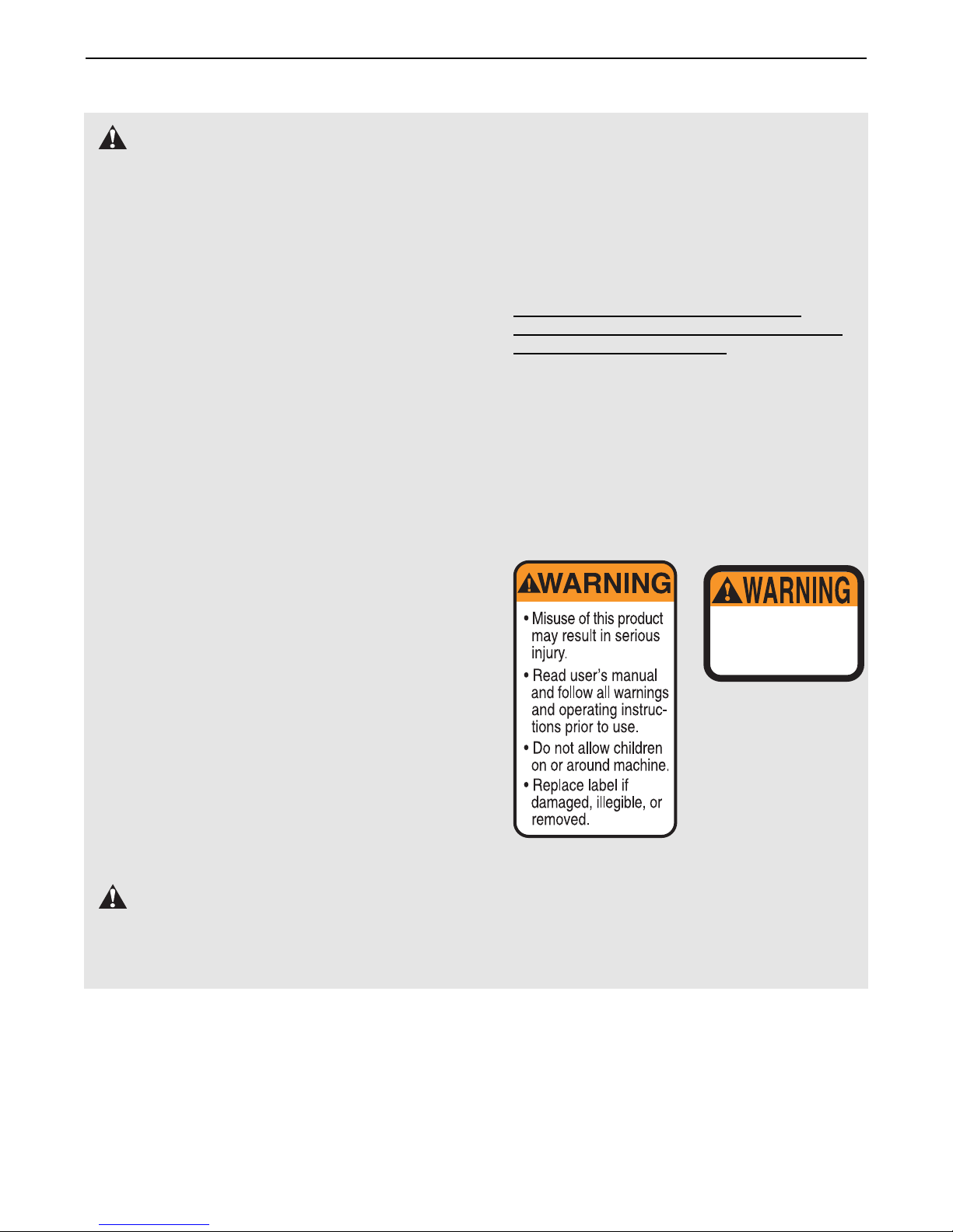
14. The decals shown below have been laced
on the weight system in the location shown
on age 4. If a decal is missing or illegible,
call our toll-free Customer Hot Line at
1-800-999-3756 and order a free re lacement
decal. A ly the decal
in the location shown.
Keep hands and
fingers clear of
this area.
Decal 2
Decal 1
4
BEFORE YOU BEGIN
SSEMBLED
DIMENSIONS:
Height: 76 in.
Width: 37 in.
Length: 48 in.
Foot Plate
Low Pulley Station
High Pulley Station
Left Side
Right Side
Lat Bar
Decal 1
Decal 2
Leg Lever
Butterfly rms
Press rm
Preacher Pad
Weight Stack
Seat
Backrest
Weight Pin
Thank you for selecting the versatile WEIDER®8525
weight system. The WEIDER®8525 offers a selection
of weight stations designed to develop every major
muscle group of the body. Whether your goal is to tone
your body, build dramatic muscle size and strength, or
improve your cardiovascular system, the WEIDER®
8525 will help you to achieve the specific results you
want.
For your benefit, read this manual carefully before
using the WEIDER®8525 weight system. If you have
additional questions, please call our Customer Service
Department toll-free at 1-800-999-3756, Monday
through Friday, 6 a.m. until 6 p.m. Mountain Time
(excluding holidays). To help us assist you, please
note the product model number and serial number
before calling. The model number is WESY19510. The
serial number can be found on a decal attached to the
weight system (see the front cover of this owner's
manual).
Before reading further, please review the drawing
below and familiarize yourself with the parts that are
labeled.
Note: The terms “right side” and “left side”
are determined relative to a erson sitting
on the seat; they do not corres ond to right
and left on the drawings in the manual.
5
1
56
High Side of Bracket
3
5
51
51 14
1
27
4
1. Before beginning assembly, be sure that you
have read and understand the information in
the box above.
Press a 2” Square Outer Cap (51) onto each end
of the Stabilizer (5). Press a 2” Square Inner Cap
(27) into the end of the Base (4).
Insert two 5/16” x 2 3/4” Carriage Bolts (14) up
through the Stabilizer (5). Insert two 5/16” x 2 1/2”
Carriage Bolts (1) up through the Base (4).
Slide the indicated end of the Base (4) onto the
5/16” x 2 3/4” Carriage Bolts (14) in the Stabilizer
(5). Slide the Rear Upright (56) onto the Carriage
Bolts. Hand tighten a 5/16” Nylon Locknut (3)
onto each Carriage Bolt. The high side of the
bracket on the Rear U right must be on the
side shown. Do not tighten the Nylon
Locknuts yet.
Frame Assembly
•ssembly requires two people.
•Place all parts in a cleared area and remove the
packing materials. Do not dispose of the packing
materials until assembly is completed.
•Tighten all parts as you assemble them, unless
instructed to do otherwise.
•s you assemble the weight system, make sure
all parts are oriented as shown in the drawings.
•For help identifying small parts, use the P RT
IDENTIFIC TION CH RT at the center of this
manual.
The following tools (not included) are required
for assembly:
• Two adjustable wrenches
• One rubber mallet
• One standard screwdriver
• One Philli s screwdriver
• Lubricant, such as grease or etroleum jelly,
and soa y water.
ssembly will be more convenient if you have a
socket set, a set of open-end or closed-end
wrenches, or a set of ratchet wrenches.
Make Things Easier for Yourself
Everything in this manual is designed to ensure
that the weight system can be assembled suc-
cessfully by anyone. However, it is important to
realize that the weight system has many parts
and that the assembly process will take time.
Most people find that by setting aside plenty of
time, assembly will go smoothly.
ASSEMBLY
6
2. Slide the Front Upright (42) onto the 5/16” x
2 1/2” Carriage Bolts (1) in the Base (4). Hand
tighten a 5/16” Nylon Locknut (3) onto each
Carriage Bolt. Do not tighten the Nylon
Locknuts yet.
Press a 1” Square Inner Cap (65) into the Front
Upright (42).
3. Press a 2” Square Inner Cap (27) into each end
of the Top Frame (55). Press a 1 3/4” Square
Inner Cap (44) into each end of the crossbar on
the Top Frame. Press two Round Inner Caps (77)
into the top of the crossbar.
ttach the Top Frame (55) to the Front Upright
(42) and the Rear Upright (56) with four 5/16” x
2 3/4” Bolts (11), four 5/16” Flat Washers (8), and
four 5/16” Nylon Locknuts (3).
Tighten the Nylon Locknuts used in ste s 1–3.
4. Set two Weight Bumpers (19) onto the bracket on
the Base (4) as shown.
Stack the six Weights (25) on the Weight
Bumpers (19). Be sure that all of the Weights are
turned so the large pin grooves are on the bottom
of the Weights and on the same side of the
weight stack. Be careful not to ti the stack of
Weights.
4
2
3
42
65
3
1
4
11 11
77
8
44
44
27
27
55
56 42
3
Crossbar
25
Pin Groove
19
4
Bracket
3
8
7
5. Press the Weight Tube Bumper (64) into the end
of the Weight Tube (63). Insert the Weight Tube
into the stack of Weights (25). Be sure that the
pins on the Weight Tube are resting in the pin
grooves in the upper Weight.
Lubricate the insides of the holes in the Top
Weight (76). Set the Top Weight onto the stack of
Weights (25).
Insert both Weight Guides (62) into the stack of
Weights (25). Be sure that the holes in the
Weight Guides are at the to , as shown.
6. ttach the upper ends of the Weight Guides (62)
to the Top Frame (55) with the 5/16” x 6” Bolt
(60), two 1/2” x 3/4” Spacers (61), and a 5/16”
Nylon Locknut (3).
Be sure that the Pulley Bracket (20) is in front
of the right Weight Guide (62) as shown.
7
5
6
55
76
63
64
25
62
Lubricate
Pin Groove
60 20
62
3
Tube
Welded
Spacers
17
Lubricate
15
21
4
75
59
61
Holes
Arm Assembly
7. Press a 1” x 7/8” Plastic Bushing (75) onto each
welded spacer on the Press Frame (17). Slide the
Press Frame into place on the Base (4). Note:
This will be a tight fit. The Plastic Bushings
should fit onto each end of the indicated tube
in the Base. Be sure that the 3 1/2” Pulley (15)
is on the indicated side.
Lubricate the 3/8” x 8” Bolt (59). ttach the Press
Frame (17) to the Base (4) with the Bolt and a
3/8” Nylon Locknut (21). Do not overtighten the
Locknut; the Press Frame must be able to
ivot freely.
8
8. Press a 1 3/4” Square Inner Cap (44) into the top
of a Press rm (46). Press a 1” Round Inner Cap
(49) into each end of the handle on the Press
rm.
ttach the Press rm (46) to one side of the
Press Frame (17) with two 5/16” x 2 1/2” Bolts
(22) and two 5/16” Nylon Locknuts (3).
ssemble the other Press rm (46) in the same
manner.
9. Identify the Right rm (48) and the Left rm (47).
Note the position of the welded bracket on each
rm. Arm identification is very im ortant for
ste 10.
Note: The “V”-Pulleys (6), Long Cable Traps (50),
3/8” x 2 1/2” Bolts (7), and 3/8” Nylon Locknuts
(21) are pre-attached. These have been shown
disassembled for easy part identification.
10. Lubricate both axles on the Top Frame (55).
Slide the Right rm (48) onto the right axle on the
Top Frame (55). Note: Be careful not to con-
fuse the Right Arm with the Left Arm (47);
refer to ste 9 to identify the Right Arm. Be
sure that the u er end of the Right Arm is
behind the indicated bracket on the To
Frame.
Tap two 1” Retainers (69) and a 1” Round Cover
Cap (70) onto the right axle. Be sure that the
teeth on the Retainers bend toward the Cover
Ca , as shown in the inset drawing.
ttach the Left rm (47) in the same manner.
Press a 1 3/4” Square Inner Cap (44) into the
lower ends of the Right and Left rms (47, 48).
Wet the end of each rm with soapy water, and
slide a 10” Pad (45) onto the rm.
10
50
50
46
3
22
46
49
49
44
17
7
44
49
Bracket
Lubricate
45
47
55
48
45
44
69
70
6
6
48
47
Welded
Brackets
21
8
9
69
55
70
9
11. During steps 11 through 24, refer to the C BLE
DI GR M on page 20 of this manual to verify
proper cable routing. Before beginning this sec-
tion, identify the Long Cable (23) and the Short
Cable (58) by comparing the lengths of the
cables.
IMPORTANT: While assembling the cables, do
not overtighten the bolts and nuts securing
the ulleys. The ulleys must be able to turn
freely.
12. Locate the Long Cable (23). Route the Long
Cable around the indicated 3 1/2” Pulley (15)
attached to the Top Frame (55). Be sure that the
Cable is between the Pulley and the hook and
that the end of the Cable with the ball is on
the indicated side of the hook. Tighten the 3/8”
x 3 3/4” Bolt (71) and the 3/8” Nylon Locknut (not
shown).
13. Wrap the Long Cable (23) around a “V”-Pulley
(6). ttach the “V”-Pulley and a Long Cable Trap
(50) to the indicated bracket on the Front Upright
(42) with a 3/8” x 2 1/2” Bolt (7) and a 3/8” Nylon
Locknut (21). Be sure that the Long Cable Tra
is ositioned to hold the Cable in lace.
14. Route the Long Cable (23) around the “V”-Pulley
(6) on the Left rm (47). Be sure that the Cable
is in the groove of the Pulley and that the
Long Cable Tra (50) is ositioned to hold the
Cable in lace. Tighten the 3/8” x 2 1/2” Bolt (7)
and the 3/8” Nylon Locknut (not shown).
14
11
12
13
58
23
55
71
Hook
Ball
15
50
23
7
47
23
7
21
6
50
23
6
42
Cable Assembly
10
15. Route the Long Cable (23) around the “V”-Pulley
(6) on the Right rm (48). Be sure that the
Cable is in the groove of the “V”-Pulley and
that the Long Cable Tra (50) is turned to hold
the Cable in lace. Tighten the 3/8” x 2 1/2” Bolt
(7) and the 3/8” Nylon Locknut (not shown).
16. Route the Long Cable (23) around the 3 1/2”
Pulley (15) attached to the Pulley Bracket (20).
Be sure that the Cable is in the groove of the
Pulley and that the Cable Tra (66) is turned
to hold the Cable in lace. Tighten the 3/8” x 2”
Bolt (12) and the 3/8” Nylon Locknut (not shown).
Be sure that the 5/16” x 5” Bolt (68) is properly
tightened and that the Pulley Bracket (20) can
move freely.
17. See the inset drawing. ttach a 3 1/2” Pulley (15)
and a Cable Trap (66) to the indicated hole in the
Long “U”-Bracket (57) with a 3/8” x 2” Bolt (12)
and a 3/8” Nylon Locknut (21). Be sure that the
Cable Tra is inside the “U”-Bracket. Note:
This may come re-assembled.
Route the Long Cable (23) between the 3 1/2”
Pulley (15) and the Cable Trap (66). Be sure that
the Cable is in the groove of the Pulley and
that the Cable and Pulley move smoothly.
18. Note: The 3 1/2”Pulley (15) in this drawing is
re-assembled. It is shown disassembled for
easy art identification.
Route the Long Cable (23) around the 3 1/2”
Pulley (15) attached to the bracket on the Top
Frame (55). Tighten the 3/8” x 2” Bolt (12) and
the 3/8” Nylon Locknut (21). Be sure that the
Cable is in the groove of the Pulley and that
the Cable and Pulley move smoothly.
18
15
16
17
48
50 76
23
66
15
12
20
68
23
21
12
15
23
57
66
12
15
23
Bracket
55
21
23