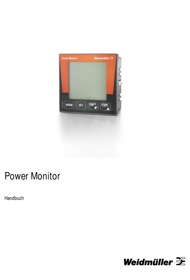
Weidmüller 525 User manual

Energy Meter 525
Manual


32576800000/00/02-2018
Error messages ........................................................................ 37
Technical data........................................................................... 40
Function parameters ............................................................ 42
Table 1 - Parameter list ........................................................ 43
Number formats ................................................................... 46
Dimensional drawings.......................................................... 47
Measured value displays overview......................................... 48
Connection example ................................................................ 51
Basic functions quick guide.................................................... 52
TCP/IP addressing quick guide............................................... 53
Table of contents
General ........................................................................................ 4
Inspection on receipt ................................................................. 5
Scope of delivery – Energy Meter 525................................... 6
Product description.................................................................... 6
Intended use .......................................................................... 6
Performance characteristics – Energy Meter 525.................. 7
Measuring method ................................................................. 7
Operating concept.................................................................. 7
ecoExplorer go network analysis software............................. 7
Connection variants ............................................................... 8
Assembly..................................................................................... 8
Installation................................................................................... 9
Supply voltage........................................................................ 9
Voltage metering .................................................................. 10
Current measurement .......................................................... 13
Ethernet interface................................................................. 17
Operation................................................................................... 18
Display mode ....................................................................... 18
Programming mode.............................................................. 18
Parameters and measured values ....................................... 19
Conguration............................................................................ 21
Applying the supply voltage ................................................. 21
Current and voltage transformers ........................................ 21
Programming current transformers ...................................... 22
Programming voltage transformers...................................... 22
Programming parameters .................................................... 23
TCP/IP conguration............................................................ 24
Parameters................................................................................ 26
User password (addr. 050)................................................... 26
Mean value........................................................................... 26
Averaging method ................................................................ 26
Min. and max. values ........................................................... 26
Energy meter........................................................................ 27
Mains frequency (Addr. 034) ................................................ 27
Harmonics ............................................................................ 28
Measured value relay........................................................... 28
Measured value displays...................................................... 28
Reset energy meter (Addr. 507)........................................... 29
Phase sequence .................................................................. 30
LCD contrast (Addr. 035) ..................................................... 30
Backlight............................................................................... 30
Time recording ..................................................................... 31
Operating hours meter ......................................................... 31
Serial number (Addr. 754) .................................................... 31
Commissioning......................................................................... 32
Applying the supply voltage ................................................. 32
Applying the measured voltage............................................ 32
Applying the measured current ............................................ 32
Rotation eld direction.......................................................... 32
Checking the phase assignment.......................................... 32
Checking the power measurement ...................................... 32
Checking the measurement ................................................. 32
Checking the individual power ratings.................................. 32
Check the sum power ratings............................................... 33
Comparators and monitoring threshold values .................... 33
Comparator in the ecoExplorer go software......................... 35
Service and maintenance ........................................................ 36
Service ................................................................................. 36
Device calibration................................................................. 36
Calibration intervals.............................................................. 36
Firmware update .................................................................. 36

4 2576800000/00/02-2018
General
General
This manual applies to the products:
Energy Meter 525-24 2540880000
Energy Meter 525-230 2540890000
Copyright
This operating manual is subject to the legal requirements for
copyright protection and may not be, either in whole or in part,
photocopied, reprinted, or reproduced by mechanical or electronic
means, or in any other manner be duplicated or redistributed with-
out the legally binding, written agreement of
Weidmüller Interface GmbH & Co. KG
Klingenbergstraße 16
32758 Detmold
Germany
Trademarks
All trademarks and their resulting rights belong to the respective
holders of these rights.
Disclaimer
Weidmüller takes no responsibility for errors or defects within this
operating manual and takes no responsibility for keeping the con-
tents of this operating manual up to date.
Comments on the operating manual
We welcome your comments. In the event that anything in this
operating manual seems unclear, please let us know and send us
an E-mail to: info@weidmueller.com
Meaning of the symbols
The following pictograms are used in the operating manual at
hand:
Dangerous voltage!
Danger to life or risk of serious injury. Disconnect
system and device from power supply before begin-
ning work.
Caution!
Please follow the documentation. This symbol warns
of possible dangers that can arise during installation,
commissioning and use.
Note!

52576800000/00/02-2018
Inspection on receipt
Instructions for use
Please read the operating manual at hand as well as all other pub-
lications that must be drawn from for working with this product (in
particular for the installation, operation or maintenance).
Follow all safety regulations and warning information. If you do not
follow the information, it can result in bodily injury and/or damage
to the product.
Any unauthorized changes or use of this device, which transcend
the mechanical, electrical or otherwise stated operating limitations,
can result in bodily injury or/and damage to the product.
Any of such unauthorized changes constitute „misuse“ and/or
„negligence“ in terms of the warranty for the product and therefore
eliminates the warranty for covering any potential damage result-
ing from this.
This device is to be operated and maintained exclusively by spe-
cialized personnel.
Specialized personnel are persons, that based on their respec-
tive training and experience, are qualied to recognize risks and
prevent potential dangers that can be caused by the operation or
maintenance of the device.
Additional legal and safety regulations required for the respective
application are to be following during the use of the device.
If the device is not operated according to the operating
manual, protection is no longer ensured and danger
can come from the device.
All signals connected with the device’s SELV circuit must
also conform with the SELV provisions.
Conductors made from single wires must be tted with
wire-end ferrules.
Only pluggable screw terminals with the same number
of poles and the same type of construction are permit-
ted to be connected together.
Concerning these operating instructions
These operating instructions are a part of the product.
• Read the operating instructions before using the device.
• Keep the operating instructions throughout the entire service life
of the product and have them readily available for reference.
• Pass the operating instructions on to each subsequent owner or
user of the product.
Inspection on receipt
The prerequisites of faultless, safe operation of this device are
proper transport and proper storage, set-up and assembly, as well
as careful operation and maintenance. If it can be assumed that
risk-free operation is no longer possible, the unit must be immedi-
ately put out of operation and secured against being put back into
operation again.
The packing and unpacking must be carried out with the custom-
ary care without the use of force and only using suitable tools.
The devices should be visually checked for awless mechanical
condition.
It can be assumed that risk-free operation is no longer possible if
the device, for example,
• has visible damage
• no longer works despite the mains power supply being intact
• has been exposed to long-term adverse conditions (e.g. storage
outside the permissible climate limits without being adapted to
the room climate, condensation etc.) or rough handling during
transportation (e.g. fall from a height, even if there is no visible
external damage etc.)
• Please check the delivered items for completeness before you
start installing the device.
All screw-type terminals included in delivery are at-
tached to the device.

6 2576800000/00/02-2018
Product description
Scope of delivery – Energy Meter 525
Quantity Description
1 Energy Meter 525
2 Mounting clips
1 Quick guide
1 Screw-type terminal, pluggable, 2-pole (auxiliary
power)
1 Screw-type terminal, pluggable, 4-pole (voltage
measurement)
1 Screw-type terminal, pluggable, 6-pole (current
measurement I1-I3)
Product description
Intended use
The Energy Meter 525 is provided for the measurement and cal-
culation of electrical parameters such as voltage, current, power,
energy, harmonics, etc. for building installations, to distributors,
circuit breakers and busbar trunking systems.
The Energy Meter 525 is suitable for installation in permanent,
weatherproof switchboards. Conducting switchboards must be
earthed. It can be mounted in any position.
Measurement voltages and measurement currents must originate
from the same grid.
The measurement results can be displayed and can be read and
processed over the Ethernet interface.
The voltage measurement inputs are designed for measuring in
low voltage grids in which nominal voltages up to 300 V phase can
occur in countercurrent with ground and overvoltages of overvolt-
age category III.
The Energy Meter 525 current measurement inputs are connected
via external ../1A or ../5A current transformers.
Measurements in medium and high voltage systems generally use
current and voltage transformers.
The Energy Meter 525 can be used in residential and industrial
areas.
Device characteristics
• Installation depth: 45 mm
• Supply voltage
Option 230 V: 90 to 277 V (50/60 Hz) or
DC 90 to 250 V; 300 V CATIII
Option 24 V: 24 to 90 V AC/DC; 150V CATIII
• Frequency range: 45 to 65 Hz
Device functions
• 3 voltage measurements, 300 V
• 3 Scurrent measurements (via current transformer ../5A or ../1A)
• Ethernet interface

72576800000/00/02-2018
Product description
Performance characteristics – Energy Meter 525
General
• Front panel integration device with dimensions 96 x 96 mm
• Connection via pluggable screw terminals
• LCD display with backlighting
• Operation via 2 buttons
• 3 voltage measurements inputs (300 V CAT III)
• 3 current measurement inputs for current transformer
• Ethernet interface
• Working temperature range -10 to +55 °C
• Storage of minimum and maximum values (without time stamp)
Uncertainty in measurement
• ctive energy uncertainty in measurement class 0.5 for ../5A
transformer
• Active energy uncertainty in measurement class 1 for ../1A
transformer
• Reactive energy, class 2
Measurement
• Measurement in IT, TN and TT networks
• Measurement in networks with nominal voltage up to L-L 480 V
and L-N 277 V
• Measuring range current 0 to 5 A eff.
• True RMS (TRMS)
• Continuous sampling of the voltage and current measurement
inputs
• Frequency range of the mains frequency 45 to 65 Hz.
• Measurement of harmonics 1 to 40 for ULN and I.
• Uln, I, P (import/delivery), Q (ind./cap.).
• Fourier analyses 1 to 40. harmonic for U and I.
• 7 power meter for
Active energy (import), Active energy (export), Active energy
(without a backstop), Reactive energy (ind.), Reactive energy
(capacitive), Reactive energy (without a backstop), Apparent
energy, each for L1, L2, L3 and total.
Measuring method
The Energy Meter 525 measures uninterrupted and calculates
all root mean squares over a 10/12-period interval (200 ms). The
Energy Meter 525 measures the true root mean square (TRMS) of
the voltages and currents applied to the measuring inputs.
Operating concept
There are several ways to program the Energy Meter 525 and re-
trieve measured values.
• Directly on the device using two buttons.
• Via the programming software of the ecoExplorer go.
These operating instructions only describe the operation of the
Energy Meter 525 using the 2 buttons.
The programming software of the ecoExplorer go has its own
documentation.
ecoExplorer go network analysis software
The Energy Meter 525 can be programmed and read with the
ecoExplorer go network analysis software. For this a PC must be
connected to the Energy Meter 525 via Ethernet.
Characteristics of ecoExplorer go software
• Programming the Energy Meter 525
• Graphic representation of measured values

8 2576800000/00/02-2018
Assembly
Connection variants
Direct connection of a Energy Meter 525 to a PC via Ethernet.
(Twisted patch cable)
ecoExplorer go
ecoExplorer go
ecoExplorer go
ecoExplorer go
Energy
Meter 525
Connecting a Energy Meter 525 to a PC via Ethernet.
(Twisted patch cable)
ecoExplorer go
ecoExplorer go
ecoExplorer go
ecoExplorer go
Energy
Meter 525
Switch
Assembly
Installation location
The Energy Meter 525 is suitable for installation in permanent,
weatherproof switchboards. Conducting switchboards must be
earthed.
Installation position
The Energy Meter 525 must be installed vertically in order to
achieve sufcient ventilation. The clearance to the top and bottom
must be at least 50 mm and 20 mm at the sides.
Front panel cutout
Cutout dimensions:
92+0,8 x 92+0,8 mm.
Fig.: Energy Meter 525 installation location (rear view)
Failure to comply with the minimum spacing can de-
stroy the Energy Meter 525 at high ambient tempera-
tures!

92576800000/00/02-2018
Installation
Mounting
The Energy Meter 525 is mounted on the switchboard by the side
mounting brackets. These must be removed before using the de-
vice. Mounting is carried out by inserting and engaging the brack-
ets.
Fig.: Energy Meter 525 mounting bracket (side view)
Failure to comply with the minimum spacing can de-
stroy the Energy Meter 525 at high ambient tempera-
tures!
Installation
Supply voltage
A supply voltage is required to operate the Energy Meter 525.
The voltage supply is connected via plug-in terminals on the back
of the device.
Before applying the supply voltage, ensure that the voltage and
frequency correspond with the details on the nameplate!
Separator
Fuse
N
L
Fig.: Connection example of the supply voltage to the Energy
Meter 525
• The supply voltage must be connected through a fuse
according to the technical data.
• In building installations, the supply voltage must be pro-
vided with a disconnect switch or circuit breaker.
• The disconnect switch must be attached near the de-
vice and must be easily accessible by the user.
• The switch must be labelled as a separator for this de-
vice.
• Voltages that exceed the permissible voltage range can
destroy the device.

10 2576800000/00/02-2018
Installation
Voltage metering
The Energy Meter 525 can be used for voltage measurement in
TN, TT and IT systems.
Voltage measurement in the Energy Meter 525 is designed for the
300 V overvoltage category CAT III (4 kV rated pulse voltage).
DC
AC/DC
PE
277V/480V 50/60Hz
L2
L3
N
L1
Auxiliary energy
Measuring voltage
4M
4M
4M
4M
V1 V3V2 VN
Energy Meter 525
N
L1
240V
50/60Hz
Fig.: Principle circuit diagram - Measurement in three-phase
4-wire systems.
In systems without a neutral, measured values that require a neu-
tral refer to a calculated neutral.
480V 50/60Hz
DC
AC/DC
L2
L3
Auxiliary energy
Measuring voltage
4M
4M
4M
4M
V1 V3V2
System
earthing
Impedance
L1
VN
Energy Meter 525
Fig.: Principle circuit diagram - Measurement in three-phase
3-wire systems.
Rated mains voltage
Lists of the networks and their rated mains voltage in which the
Energy Meter 525 can be used.
Three-phase 4-wire systems with earthed neutral conductor.
UL-N / UL-L
66V / 115V
120V / 208V
127V / 220V
220V / 380V
230V / 400V
240V / 415V
260V / 440V
277V / 480V Maximum rated voltage of the network
Fig.: Table of the rated mains voltages suitable for the voltage
measuring inputs according to EN 60664-1:2003.
Unearthed three-phase, 3-wire systems.
UL-L
66V
120V
127V
220V
230V
240V
260V
277V
347V
380V
400V
415V
440V
480V Maximum rated voltage of the network
Fig.: Table of the rated mains voltages suitable for the voltage
measuring inputs according to EN 60664-1:2003.

112576800000/00/02-2018
Installation
Voltage measurement inputs
The Energy Meter 525 has three voltage measurement inputs (V1,
V2, V3).
Overvoltage
The voltage measurement inputs are suitable for measurement
in networks in which overvoltages of overvoltage category 300 V
CAT III (4 kV rated pulse voltage) can occur.
Frequency
The Energy Meter 525 requires the mains frequency for the meas-
urement and calculation of measured values.
The Energy Meter 525 is suitable for measurements in the fre-
quency range of 45 to 65 Hz.
Separator
Fuse
L2
L3
N
L1
Fig.: Connection example for the voltage measurement
When connecting the voltage measurement, the following must be
observed:
Isolation device
• A suitable circuit breaker must be tted to disconnect and de-
energise the Energy Meter 525.
• The circuit breaker must be placed in the vicinity of the Energy
Meter 525, be marked for the user and easily accessible.
• The circuit breaker must be UL/IEC certied.
Overcurrent protection device
• An overcurrent protection device must be used for line protec-
tion.
• For line protection, we recommend an overcurrent protection
device as per the technical specications.
• The overcurrent protection device must be suitable for the line
cross section used.
• The overcurrent protection device must be UL/IEC certied.
• A circuit breaker can be used as an isolating and line protec-
tion device. The circuit breaker must be UL/IEC certied.
• Measured vo ltages and measured currents must derive
from the same network.
Attention!
Voltages that exceed the permitted ratedmains volt-
ages must be connected via voltage transformers.
Attention!
The Energy Meter 525 is not suitable for the measure-
ment of DC voltages.
Attention!
The voltage measurement inputs on the Energy
Meter 525 are dangerous to touch!

12 2576800000/00/02-2018
Installation
Connection diagram, voltage measurement
• 3p 4w (addr. 509= 0), factory setting
L1
L2
L3
N
V1 V2 V3 VN
Fig.: System with three-phase conductors and a neutral conduc-
tor.
• 3p 4u (addr. 509 = 2)
L1
L2
L3
V1 V2 V3 VN
Fig.: System with three-phase conductors and no neutral conduc-
tor. Measured values that require a neutral refer to a calcu-
lated neutral.
• 3p 4wu (addr. 509 = 1)
L1
L2
L3
N
V1 V2 V3 VN
Fig.: System with three-phase conductors and a neutral conduc-
tor. Measurement via voltage transformer.
• 3p 2u (addr. 509 = 5)
L1
L2
L3
V1 V2 V3 VN
Fig.: System with three-phase conductors and no neutral conduc-
tor. Measurement via voltage transformer. Measured values
that require a neutral refer to a calculated neutral.
• 1p 2w1 (addr. 509 = 4)
L1
N
V1 V2 V3 VN
Fig.: Measured values derived from the V2 and V3 voltage meas-
urement inputs are assumed to be zero and not calculated.
• 1p 2w (addr. 509 = 6)
L1
L2
V1 V2 V3 VN
Fig.: TN-C system with single-phase, three-wire connection.
Measured values derived from the V3 voltage measurement
input Zero are assumed to be zero and not calculated.

132576800000/00/02-2018
Installation
• 2p 4w (addr. 509 = 3)
L1
L2
L3
N
V1 V2 V3 VN
Fig.: System with uniform phase loading. The measured values
for the V2 voltage measurement input are calculated.
• 3p 1w (addr. 509 = 7)
L1
L2
L3
L1
L2
L3
L1
L2
L3
V1 V2 V3 VN
N
Fig.: Three systems with uniform phase loading. The measure-
ment values L2/L3 resp. L1/L3 resp. L1/L2 of the respective
system are calculated.
Current measurement
The Energy Meter 525 is designed for connecting current trans-
formers with secondary currents of ../1A and ../5A. The factory set
current transformer ratio is 5/5 A and may need to be adapted to
the current transformers.
It is not possible to perform a direct measurement without a current
transformer with the Energy Meter 525.
Only AC currents (and not DC currents) can be measured.
The test leads must be designed for an operating temperature of
at least 80°C.
L2
L3
N
L1
Load
Fig.: Current measurement via current transformer (connection
example)
Earthing of current transformers!
If a connection is provided for the earthing of second-
ary windings then this must be connected to the earth.
Attention!
The Energy Meter 525 is not suitable for the measure-
ment of DC voltages.
Attention!
The current measurement inputs are dangerous to
touch.
The attached screw terminal has to be xed sufciently
with two screws on the device!

14 2576800000/00/02-2018
Installation
Direction of the current
The current direction can be individually corrected on the device or
via the serial interfaces for each phase.
In the case of incorrect connection, the current transformer does
not need to be subsequently reconnected.
Earthing of current transformers!
If a connection is provided for the earthing of second-
ary windings then this must be connected to the earth.
Current transformer connections!
The secondary connection of the current transformer
must be short-circuited on this before the current feed
to the Energy Meter 525 is disconnected!
If a test switch, which automatically short-circuits the
secondary wires of the current transformer, is avail-
able then it is sufcient to set this to the „Test“ position
insofar as the short-circuiting device has been checked
beforehand.
Open-circuit current transformers!
High voltage spikes that are dangerous to touch can
occur on current transformers that are driven with
open-circuit secondary windings!
With “safe open-circuit current transformers” the wind-
ing insulation is rated such that the current transformer
can be driven open. However, even these current
transformers are dangerous to touch when they are
driven open-circuit.

152576800000/00/02-2018
Installation
Connection diagram, current measurement
• 3p 4w (addr. 510 = 0), factory setting
L1
L2
L3
N
I1 I2 I3
Fig.: Measurement in a three-phase net-work with an unbalanced
load.
• 3p 2i0 (addr. 510 = 2)
L1
L2
L3
I1 I2 I3
Fig.: The measured values for the I2 current measurement input
are calculated.
• 3p 2i (addr. 510 = 1)
L1
L2
L3
N
I1 I2 I3
Fig.: System with uniform phase loading. The measured values
for the I2 current measurement input are measured.
• 3p 3w3 (addr. 510 = 3)
L1
L2
L3
I1 I2 I3
Fig.: Measurement in a three-phase net-work with an unbalanced
load.
• 3p 3w (addr. 510 = 4)
L1
L2
L3
N
I1 I2 I3
Fig.: System with uniform phase loading. The measured values
for the I2 and I3 current measurement inputs are calculated.
• 1p 2i (addr. 510 = 6)
I1 I2 I3
L1
L2
Fig.: Measured values derived from the I3 current measurement
input are assumed to be zero and not calculated.

16 2576800000/00/02-2018
Installation
• 2p 4w (addr. 510 = 5)
L1
L2
L3
N
I1 I2 I3
Fig.: System with uniform phase loading. The measured values
for the I2 current measurement input are calculated.
• 1p 2w (addr. 510 = 7)
L1
N
I1 I2 I3
Fig.: Measured values derived from the I2 and I3 current meas-
urement inputs are assumed to be zero and not calculated.
• 3p 1w (addr. 510 = 8)
L1
L2
L3
I1 I2 I3
L1
L2
L3
L1
L2
L3
Fig.: Three systems with uniform phase loading. The current
measurement values of the phases of the respective system
where are no CTs connected are calculated (I2/I3 resp. I1/I3
resp. I1/I2).
Caution!
The Energy Meter 525 is only approved for a current
measurement using the current transformer.

172576800000/00/02-2018
Installation
Ethernet interface
The Ethernet network settings should be specied by the network
administrator and set on Energy Meter 525 accordingly.
If the network settings are not known, the Energy Meter 525 may
not be integrated into the network through the patch cable.
PC / Switch
Ethernet
Connection
Caution!
Connection of the Energy Meter 525 to the Ethernet
may only be carried out after discussion with the net-
work administrator!
Caution!
The Energy Meter 525 is factory-programmed for the
dynamic allocation of the IP settings (DHCP mode).
Settings can be changed as described in TCP/IP Con-
guration or, for example, via an appropriate Ethernet
connection by means of ecoExplorer go software.
Ammeter
If you want to measure the current not only with the Energy
Meter 525 but also with the ammeter, the ammeter must be con-
nected in series with the Energy Meter 525.
Energy Meter
S2
I
S1
Einspeisung
Supply
Verbraucher
Consumer
A
(k)S
1S2(l)
P2(L)(K)P1
Fig.: Current measurement with an additional ammeter (exam-
ple).
Total current measurement
If the current measurement takes place via two current transform-
ers, the total transformer ratio of the current transformer must be
programmed in the Energy Meter 525.
Energy Meter
S2
I
S1
P1P2
Einspeisung 1
Supply 1
Einspeisung 2
Supply 2
1P1
1P2
(K)
(L)
(k)
(l)
1S2
1S1
1S11S22S12S2
2S1
2S2
(k)
(l)
(K)
(L)
2P1
2P2
Verbraucher A
Consumer A
Verbraucher B
Consumer B
Fig.: Current measurement via a total current transformer (exam-
ple).
Example:
The current measurement takes place via two current transform-
ers. Both current transformers have a transformer ratio of 1000/5
A. The total measurement is performed with a 5+5/5 A total current
transformer.
The Energy Meter 525 must then be set as follows:
Primary current: 1.000 A + 1.000 A = 2.000 A
Secondary current: 5 A

18 2576800000/00/02-2018
Operation
Operation
The Energy Meter 525 is operated via buttons 1 and 2 with the
following functions:
• briey pressing button 1 and 2:
next step (+1)
• pressing and holding button 1 and 2:
previous step (-1)
Measured values and programming data are displayed on an LCD
display.
There are display and programming modes. You can avoid an un-
intentional change of programming data by entering a password.
Display mode
In display mode, you can scroll through the programmed measured
values by pressing buttons 1 and 2. When the device is delivered,
all measured value indications of prole 1 can be retrieved. For
each measured value, up to three measured values are indicated.
The measured value rotation can display selected measured value
indications one after the other with a selectable changing time.
Programming mode
You can view and change the necessary settings of the Energy
Meter 525 in programming mode. Press button 1 and 2 simulta-
neously for about 1 second to switch to programming mode after
entering the password. If no password is programmed, you get
directly to the programming mode menu. Programming mode is
marked by the text „PRG“ on the display.
Press button 2 to switch between the following menus:
• Current transformer,
• Voltage transformer,
• Parameter list,
• TCP/IP device address,
• Subnet mask,
• Gateway address,
• Dynamic TCP/IP addressing (in/out).
If no button was pressed for about 60 seconds when you are in
programming mode, or button 1 and 2 are pressed simultaneously
for about 1 second, the Energy Meter 525 will switch back to dis-
play mode.
Button 1
Button 2
Supply
Mean value
CT: current transformer
VT: voltage
transformer
Password
External conductor
External conductor
Total measurement
Programming
mode
Min. value, NT/supply
Max. value, HT/reference

192576800000/00/02-2018
Operation
Parameters and measured values
All parameters necessary for operating the Energy Meter 525, e.g.
the current transformer data, and a selection of frequently required
measured values are stored in the table.
The contents of most addresses can be accessed via the serial
interface and the buttons on the Energy Meter 525.
Only the rst 3 signicant digits of a value can be entered
on the device. Values with more digits can be entered using
ecoExplorer go software.
The device always only displays the rst 3 signicant digits of a
value.
Selected measured values are summarised in measured value
display proles and can be shown in display mode using buttons
1 and 2.
The current measured value display prole and the current display
change prole can only be read and changed via the Ethernet in-
terface.
Example of the parameter display
On the Energy Meter 525 display the value “006” is shown as the
content of address “036”. This parameter reects the brightness of
the backlighting (0 = dark, 9 = bright).
Example of the measured value display
In this example, the Energy Meter 525 display shows the voltages
L to N with 230 V each.

20 2576800000/00/02-2018
Operation
Button functions
Password
Display mode
simultaneous
Change mode
Browse
long
short Measured
values 1a
Measured
values 2a
Measured
values 2b
long short
Programming mode
simultaneous
Change mode
Browse
long
short Programming
menu 1
Programming
menu 2
Programming
menu 3
Programming
Programming
menu 1 Conrm selection
(ashes)
Short: digit +1
Long: digit -1
(ashes)
Short: value x 10
(decimal to the right)
Long: Value /10
(decimal to the left)
Table of contents
Other Weidmüller Measuring Instrument manuals
Popular Measuring Instrument manuals by other brands

LOVATO ELECTRIC
LOVATO ELECTRIC DME D100 T1 instruction manual

SODAQ
SODAQ AIR user guide

Sierra
Sierra 780S Series Flat-Trak Quick install guide

Eaton
Eaton Cutler-Hammer Enclosed IQ Instruction leaflet

Keysight Technologies
Keysight Technologies N9030A Installation note

Fema Electronica
Fema Electronica S Series user manual