Weidmüller MultiMark User manual

MultiMark
THM MultiMark LPC
Original operating instructions

2903400000/00/09.20222
Manufacturer
Weidmüller Interface GmbH & Co. KG
Klingenbergstraße 26
32758 Detmold, Germany
T +49 5231 14-0
F +49 5231 14-292083
www.weidmüller.com
Document no. 2903400000
Revision 00/September 2022

32903400000/00/09.2022
Contents
1 About this documentation 4
2 Safety 5
2.1 General safety notes 5
2.2 Intended use 5
2.3 Safety marking 6
2.4 Personnel 6
3 Device description 7
3.1 Label printer 8
3.2 Mounting foot 9
3.3 Applicator 10
3.4 Technical data 11
3.5 Type plate 12
4 Unpacking and installing devices 13
4.1 Fitting the printer on the mounting foot 13
4.2 Fitting the applicator on the printer 14
4.3 Connecting the devices 14
4.4 Switching on the system 14
5 Operating software 15
5.1 Touch display 15
5.2 Start screen 15
5.3 Menu navigation 17
6 Setting up the printer 18
6.1 Positioning the material reel on the reel holder 18
6.2 Placing labels in the print head 18
6.3 Inserting the transfer foil 19
6.4 Adjusting the head locking system 19
6.5 Adjusting the transfer foil run 20
7 Printing 21
7.1 Synchronising the paper run 21
8 Cleaning 22
8.1 Cleaning the print roller 22
8.2 Cleaning the print head 22
8.3 Cleaning the label light barrier 23
9 Troubleshooting 24
9.1 Error display 24
9.2 Printer error messages 25
9.3 Printer problem solving 27
10 SQ laser applicator 28
10.1 Conguration 28
10.2 Test mode without print job 30
10.3 Test mode with pending print job 30
10.4 Normal operation 31
10.5 Applicator error messages 32
11 Setting up the laser pointer 34
12 Decommissioning and disposing of the system 36
12.1 Decommissioning the system 36
12.2 Disposing of the system 36
13 Annex 37

2903400000/00/09.20224
The warnings in this documentation are designed accord-
ing to the severity of the danger.
WARNING
Possible danger to life!
Notes with the signal word “Warning” warn
you of situations that may result in serious
injury or death if you do not follow the instruc-
tions given in this manual.
CAUTION
Danger of injury!
Notes with the signal word “Caution” warn
you of situations that may result in injury if
you do not follow the instructions given in this
manual.
ATTENTION
Material damage!
Notes with the signal word “Attention” warn you of haz-
ards which may result in material damage.
The situation-dependent warnings may contain the follow-
ing warning symbols:
Icon Meaning
Warning of dangerous electrical voltage
Warning of hot surfaces
Warning of automatic startup
Work must only be carried out by a qualied
electrician.
Carry out work only with personal protective
equipment
Notes on the documentation/
Observe the instructions for use
Additional formatting is used in the text, with the following
meaning:
Texts next to this arrow are notes which are not
relevant to safety, but provide important informa-
tion about proper and eective work procedures.
►You can recognise handling instructions from the black
triangle in front of the text.
– Lists are marked with a tick.
1 About this documentation

52903400000/00/09.2022
2 Safety
2.1 General safety notes
Electricity
– The enclosures of all system components must not be
opened.
– Unauthorised work or modications to the device may
place the operational reliability at risk.
– Installation work and disassembly of the system may
only be carried out if the printer is disconnected from the
mains and the compressed air supply is blocked.
– The system is designed for electricity grids with AC volt-
age of between 100 V and 240 V.
– The system may only be connected to sockets with a
protective earth contact.
– The system may only be connected to devices that con-
duct safety extra-low voltage.
Moving parts
– When operating the applicator, moving parts are acces-
sible when the stamp is moved between the home and
labelling position. Do not reach into this area during op-
eration and keep hair, loose clothing and jewellery and
the like out of this area. The compressed air supply must
be closed when working in this area.
– If the printer is operated with an open cover, make sure
that hair, loose clothing, jewellery and the like do not
come into contact with exposed, rotating parts.
Installation site
– The system is a class A installation. The installation
can cause radio interference in residential areas. In this
case, the operator may be asked to implement adequate
protective measures.
– The system may only be operated in a dry environment
and must not be exposed to moisture (spray water, mist,
etc.).
– The system must not be operated in potentially explo-
sive atmospheres.
– The system must not be operated near high-voltage
lines.
Personnel, activities
– Only carry out the actions described in these instruc-
tions. Additional work may only be carried out by trained
personnel or service technicians.
– Improper intervention in electronic assemblies and their
software can cause faults.
– Service activities must be carried out in a qualied work-
shop that has the necessary expertise and tools to per-
form the necessary work.
2.2 Intended use
The labelling system is exclusively intended for printing
and applying labels. The system may only be used to pro-
cess materials approved for the labelling system, see the
Weidmüller online catalogue. Any other use or use above
and beyond these instructions is considered incorrect use.
Observance of the documentation, including the mainte-
nance recommendations, is also part of the intended use.
The system may only be operated if it is technically intact.
The system is manufactured based on the state of the art
and the recognised safety rules. However, the use of the
system may pose a danger to life and limb for the user or
third parties and the device and other property may be im-
paired if the safety notes are not observed.

Safety
2903400000/00/09.20226
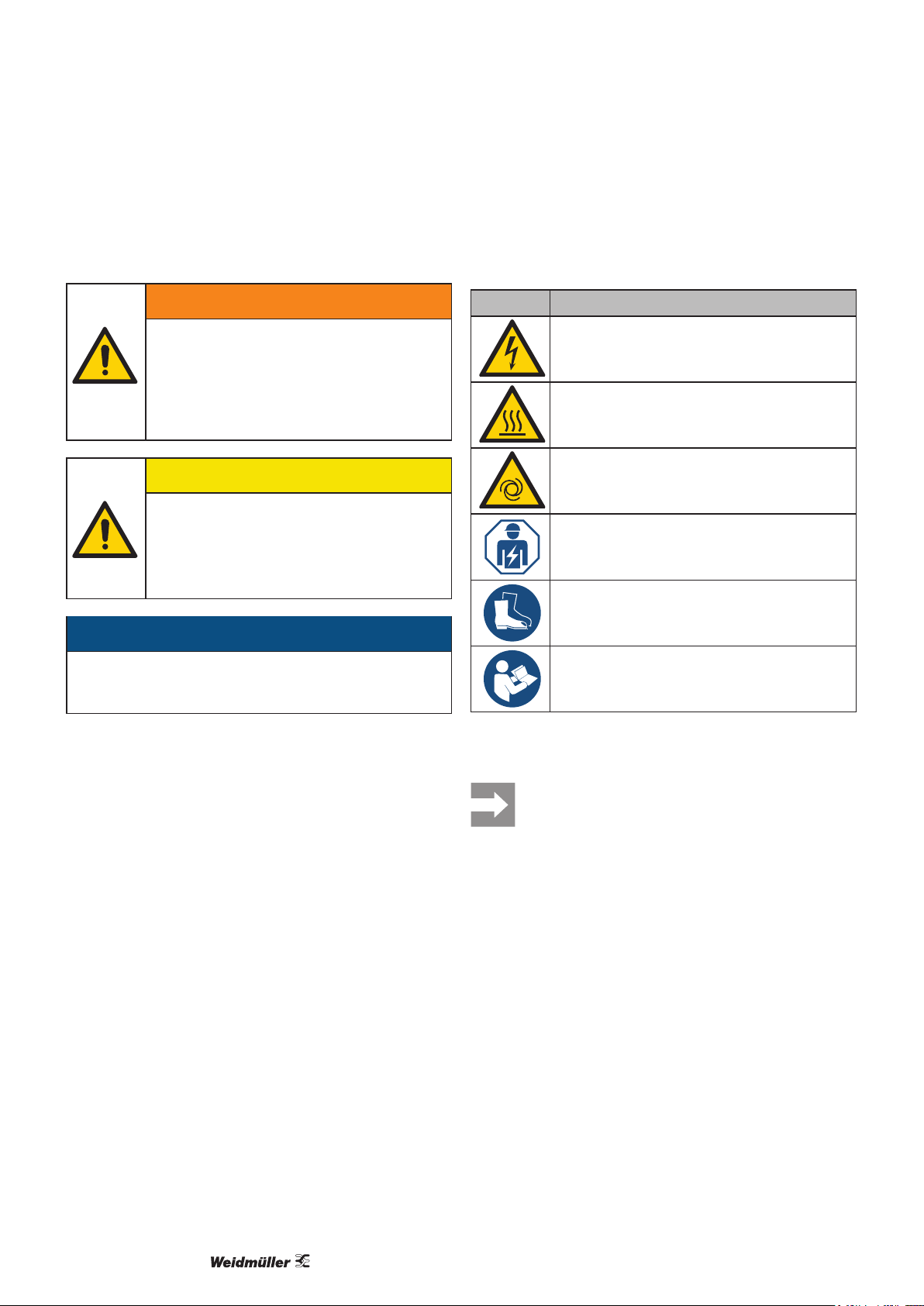
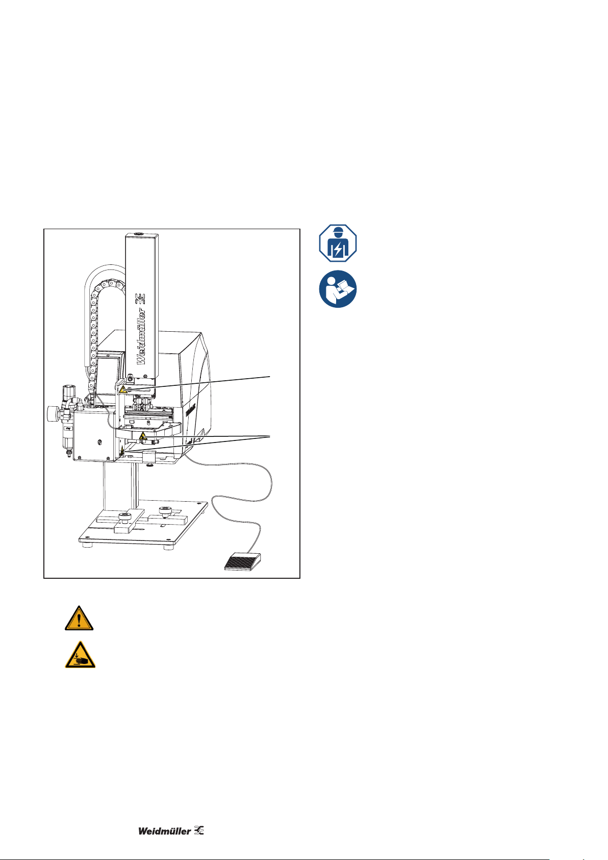
2.3 Safety marking
Various warning symbols are attached to the labelling
system. These symbols must not be removed and must
always be legible.
1
2
Image 2.1 Warning symbols on the device
1Cylinder under pressure, residual energy is
possible even when switched o!
2Risk of crushing due to the movement of the
stamp!
2.4 Personnel
Only trained personnel may operate the labelling system and
carry out maintenance work. They must also have read the
operating instructions in their entirety.
Repairs may only be carried out after consul-
tation with Weidmüller Service and only by a
qualied electrician.
Please keep the operating instructions
where they can be viewed by the operating
personnel at all times.
All documents can also be downloaded from
the Weidmüller website.

72903400000/00/09.2022
2
5
3
4
1
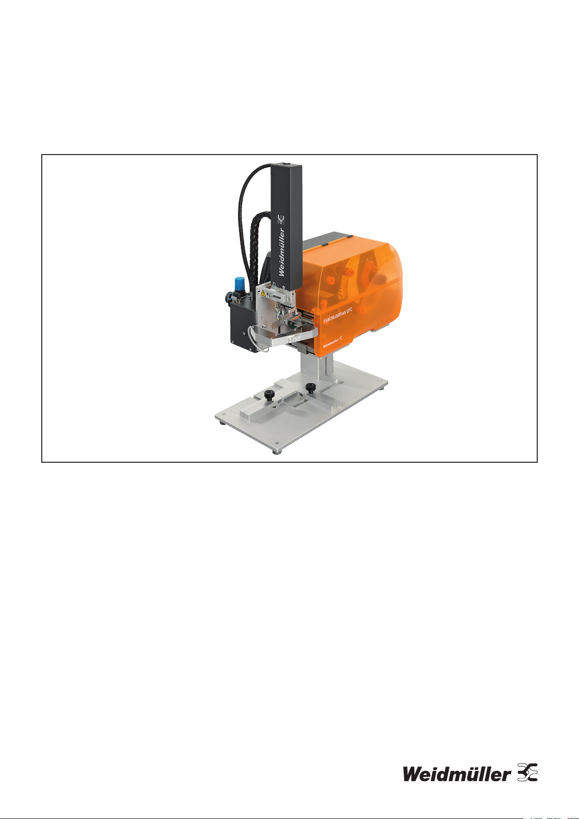
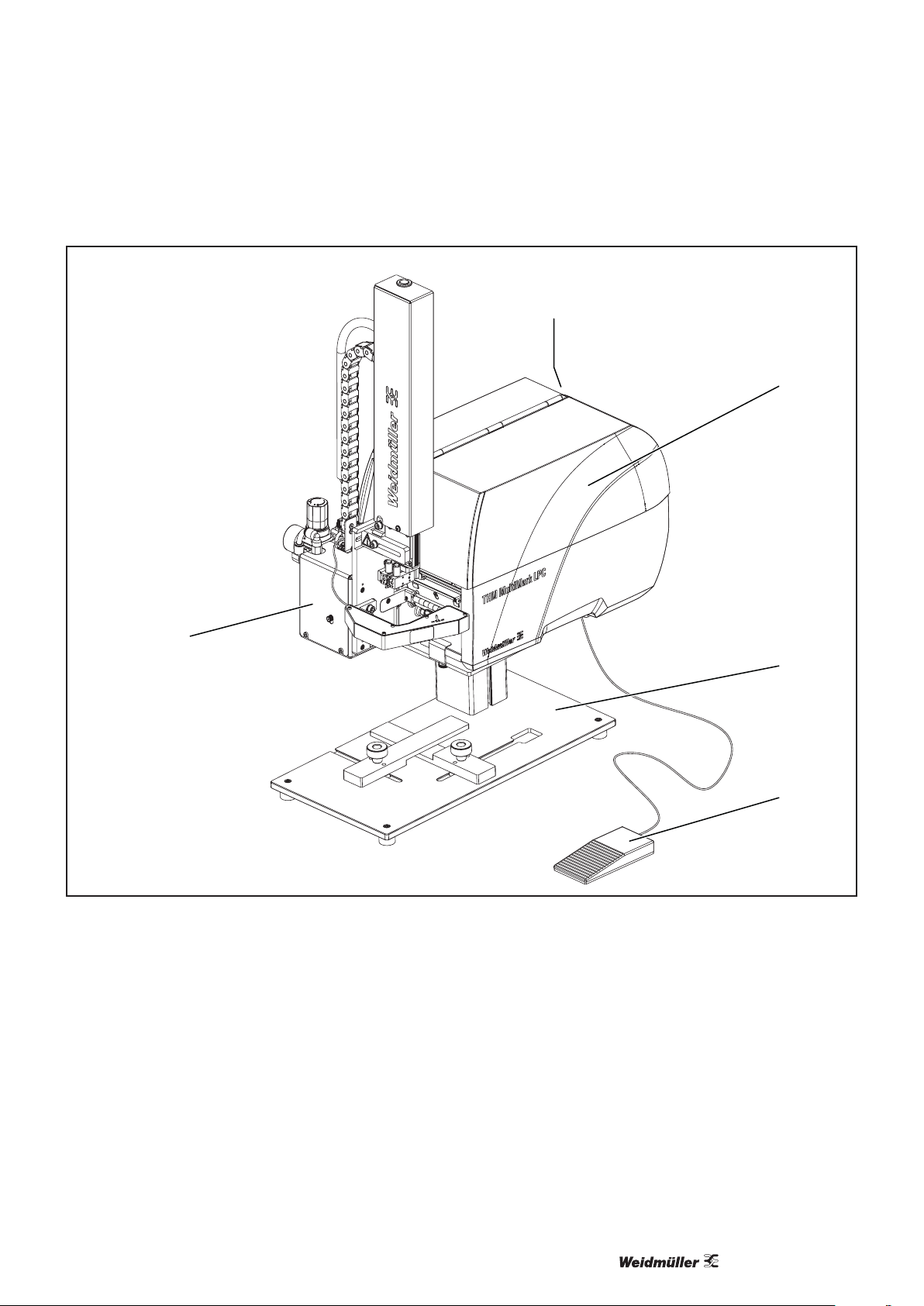
Image 3.1 Overview of the labelling system
1 Type plate
2 Label printer
3 Applicator with laser pointer
4 Mounting foot
5 Foot switch
The printer is equipped with a wide-range power supply
unit. Operation with a power supply of 230 V~/50 Hz or 115
V~/60 Hz is possible without any intervention in the device.
The applicator with the laser pointer is supplied with volt-
age by the printer.
3 Device description

Device description
2903400000/00/09.20228
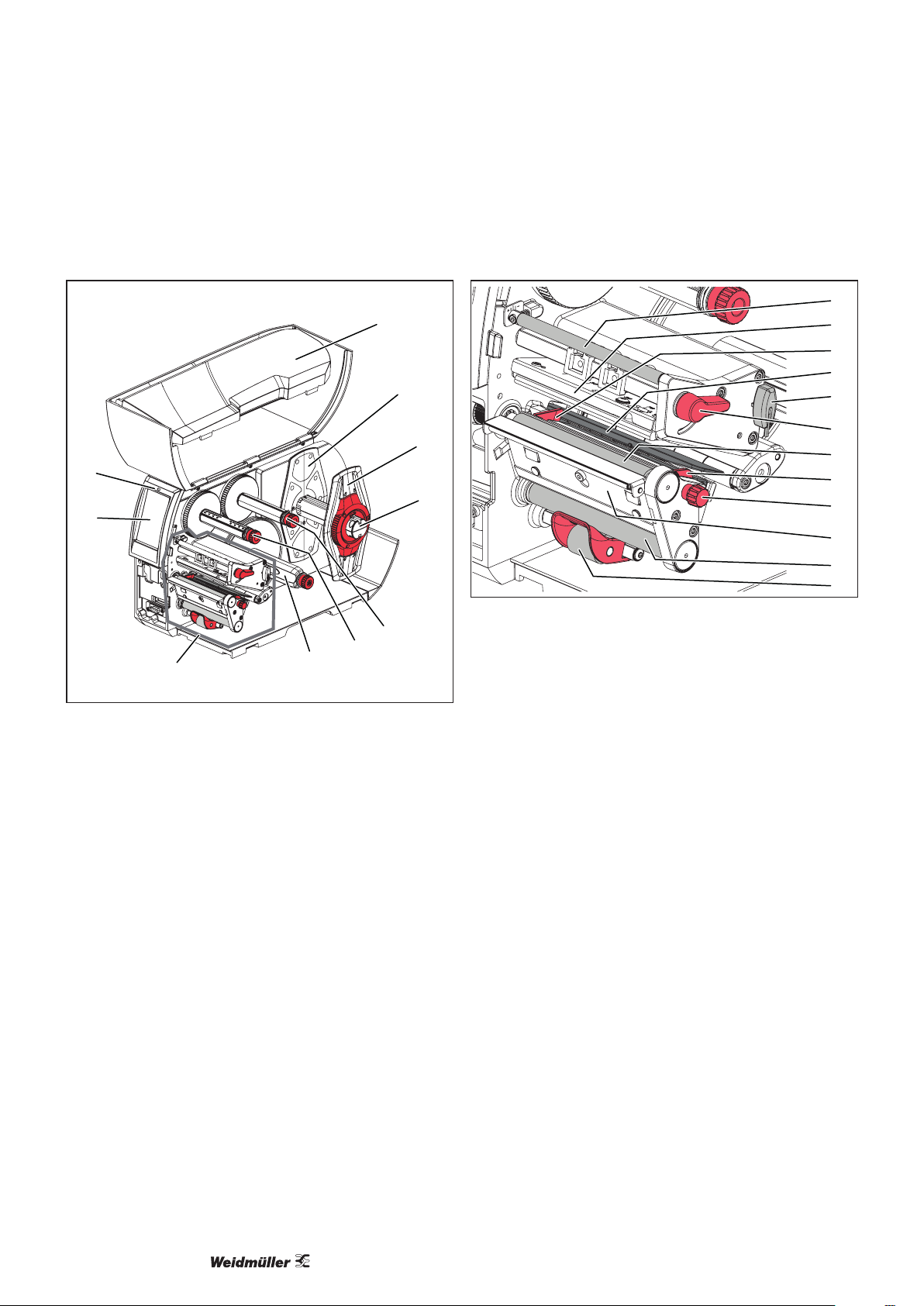
3.1 Label printer
2
3
5
6
7
8
4
1
9
10
Image 3.2 Overview of the label printer
1 Cover
2 Margin stop 1
3 Margin stop 2
4 Reel holder
5 Transfer foil unwinder
6 Transfer foil winder
7 Internal winder
8 Printing assembly
9 Touch display
10 Operating status LED
11
12
18
13
14
15
16
18
17
19
20
21
Image 3.3 Detail view of the printing assembly
11 Deflection for transfer foil
12 Head bracket with print head
13 Labelling light barrier
14 Hexagon key
15 Lever to lock the print head
16 Print roller
17 Adjusting knob for guides
18 Guide
19 Dispensing edge
20 Deflection roller
21 Locking system

92903400000/00/09.2022
Device description
22
23
26
24
25
28
27
29
30
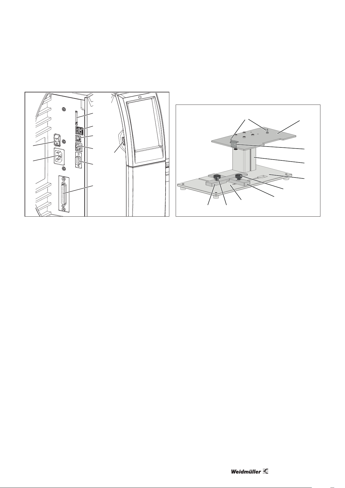
Image 3.4 Connections
22 Mains switch
23 Power socket
24 Slot for SD card
25 USB interfaces for keyboard, scanner, USB stick, Bluetooth
adapter or service key
26 USB Full Speed interface
27 Ethernet 10/100 Base-T
28 RS-232 interface
29 I/O interface
30 USB interface for keyboard, scanner, USB stick, Bluetooth
adapter or service key
3.2 Mounting foot
1
4
2
3
5
6
7
8
910
Image 3.5 Mounting foot
1 Guide pins to position the printer on the mounting plate
2 Mounting plate
3 Clip to fasten the printer on the mounting plate
4 Profile
5 Base plate with adjustable feet and positioning aids for labelling
6 Locking screw to fasten the stop (7)
7 Stop as a positioning aid in the printing direction
8 Area for object placement
9 Locking screw to fasten the stop (10)
10 Stop as a positioning aid transverse to the printing direction

Device description
2903400000/00/09.202210
3.3 Applicator
1
2
3
4
5
6
7
8
9
10
4
8910
11 12 13 14
15
16
17
3
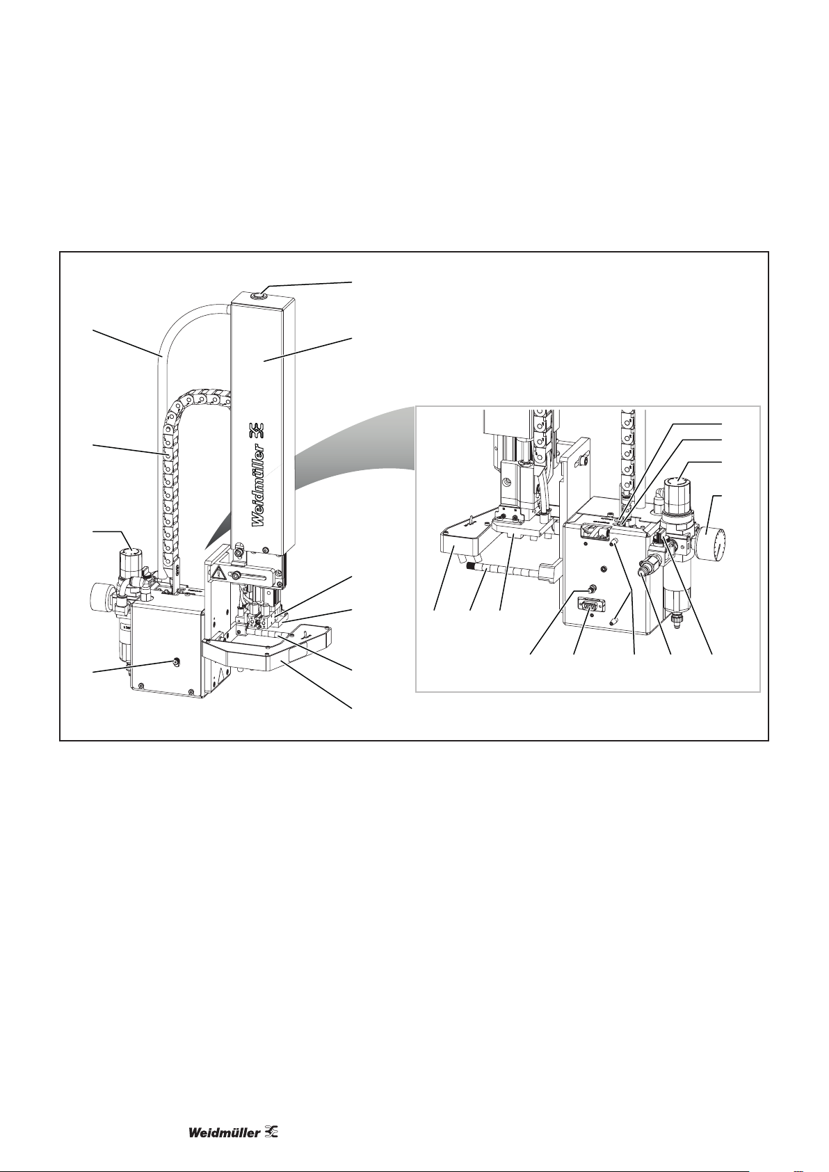
Image 3.6 Front and rear
1 Spiral hose
2 Energy chain
3 Compressed-air maintenance unit
4 Knurled screw to fasten the applicator on the printer
5 Main cylinder
6 Cylinder assembly cover
7 Mini slide
8 Stamp
9 Blowpipe for support air
10 Laser pointer
11 Interface to the printer
12 Locking pins
13 Coupling for the compressed-air connection
14 Shut-off valve
15 Pressure gauge for the working pressure
16 Throttle valve for support air
17 Throttle valve for vacuum

112903400000/00/09.2022
Device description
3.4 Technical data
General data
Ambient temperature
Operation +5°C to 40°C
Storage 0 °C to +60 °C
Transport -25 °C to +60 °C
Humidity
Operation 10 % to 85 %, non-condensing
Storage/transport 20 % to 85 %, non-condensing
Max. operating altitude 2000 m above sea level
Continuous sound pressure level < 70 dB (A)
Dimensions (WxHxD) 466 x 785 x 648 mm (18.35" x 30.91" x 25.51")
Weight 13 kg (28.66 lbs)
Supply voltage 100 to 240 V AC; 50/60 Hz, PFC
Label printer
Print technology Thermal transfer
Print quality 300 DPI
Printing speed 40 to 150 mm/s
Material guidance Centred
Interfaces RS232C: 1,200 to 230,400 baud/8 bit
1 x USB 2.0 Hi-Speed Device for PC connection
3 x USB host
Ethernet 10/100 BASE-T
Control panel LCDdisplay4.3″/272x480px
Laser Square applicator
Maximum stroke 220 mm
Stamp stroke 64 mm
Operating pressure 4.5 bar
Deviations in stack dimensions ± 0.5 mm
Number of lasers 4
Laser class 1

Device description
2903400000/00/09.202212
3.5 Type plate
1
2
5
6
9
4
7
8
3
Image 3.7 Type plate
1 Product type
2 Model
3 Material number
4 Serial number
5 Permissible voltage
6 Maximum current
7 Frequency range
8 Manufacturer
9 QR code production data
The following symbols are shown on the type plate
Icon Meaning
N
Neutral conductor fuse
EU conformity
Observe the disposal instructions
Explanation of the serial number
MLYYMM####
ML System identication
YY Year
MM Month
#### Serial number

132903400000/00/09.2022
4 Unpacking and installing devices
Select an installation site that meets the requirements, see
chapter 2.1. Observe the following additional notes:
– Stable base with a level and even surface (weight and
dimensions, see technical data).
– Easily accessible electricity and compressed air connec-
tions in the vicinity
– Compressed-air connection with min. 4.5 bar
– Adequate space for ergonomic operation, preferably in
an oce environment
Included in delivery
– Label printer
– Mounting foot
– Applicator with laser pointer
– Foot switch
– Mains cable
– USB cable
– Ink ribbon
– DVD with M-Print®PRO marking software
– Operating instructions
►Check all components for transport damage.
►Check the delivery for completeness.
Store the original packaging for subsequent
transport.
►Remove the mounting foot from the packaging and set it
up on a level surface.
►To set up the labelling system, proceed as follows:
– Fit the printer on the mounting foot, see chapter 4.1
– Fit the applicator on the printer, see chapter 4.2
– Connect the devices, see chapter 4.3
– Connect the power cable
– Switch on the system, see chapter 4.4
4.1 Fitting the printer on the mounting foot
1
2
3
4
Image 4.1 Fit the printer
►Unscrew the knurled screw (1) and loosen the clip (2).
►Position the printer with the recesses (3) on the guide
pins (4).
►Move the clip (2) over the base of the printer.
The printer must be positioned with all adjusting feet fully
on the mounting plate.
►Tighten the knurled screw (1) to fasten the printer on the
mounting plate.
►Remove the transport locks from the print head area,
see Image 3.3.

Unpacking and installing devices
2903400000/00/09.202214
4.2 Fitting the applicator on the printer
►Make sure that the printer is disconnected from the
mains.
►Ensure that the printer is in a stable position.
►Only connect the compressed air once the applicator
has been completely tted.
1
4
5
3
2
6
Image 4.2 Fit the applicator
►Guide the locking pins (1) on the rear of the applicator
into the holes (4) in the printer.
►Push the applicator against the printer.
The applicator’s connector (2) is connected to the printer’s
peripheral connection (5).
►Tighten the knurled screw (6) to secure the applicator.
►Connect the compressed air supply to the connection
(3).
4.3 Connecting the devices
The interfaces and connections are dened in the individu-
al component descriptions.
Connect the labelling system to the mains
►Make sure that the label printer is switched o.
►Insert the power cable in the mains socket (23, Image
3.4).
►Insert the power cable plug in an earthed socket.
Connecting the computer or computer network
ATTENTION
A lack of or insucient earthing can cause faults
during operation.
►Make sure that all computers connected to the label
printer as well as the connecting cables are earthed.
►Use a suitable cable to connect the label printer to the
computer or network.
4.4 Switching on the system
Prerequisites: All electrical connections to the printer as
well as the compressed-air connection on the applicator
must be in place.
►Switch on the printer at the mains switch (22, Image
3.4).
The printer runs through a system test and then shows the
Ready system status on the display (9, Image 3.2). The
applicator moves to the home position and the stamp is
located above in the transfer position for the items printed
by the printer.

152903400000/00/09.2022
5 Operating software
5.1 Touch display
The touch display lets you operate the printer’s operating
software and execute the following functions:
– Pause, continue or cancel print jobs
– Set print parameters, e.g. heat energy of the print head,
print speed, conguration of the interfaces, language
and time ( conguration instructions),
– Control the stand-alone operation with memory device
( conguration instructions),
– Perform a rmware update ( conguration instructions)
Several functions and settings can also be controlled by
printer-specic commands with software applications or by
direct programming with a computer. Details program-
ming instructions.
Settings changed on the touch display are the label print-
er’s base setting.
To adjust the print jobs, any adjustments should
take place in the software.
►To open a menu or select a menu item, tap on the rel-
evant icon.
► To scroll, move one nger up or down on the touch dis-
play.
5.2 Start screen
The start screen shows the relevant operating status.
After switching on During printing
In pause mode After a print job
Open the menu
Pause or continue a print job
Repeat last label
Cancel and delete all print jobs
Label feed
Image 5.1 Buttons on the start screen

Operating software
2903400000/00/09.202216
For certain software or hardware congurations, additional
icons are displayed on the start screen:
Print on request
without print job
Print on request in
print job
Direct cut
with connected CU,
PCU or ST cutter
Start processing a single label in the print job (printing
incl. dispensing, cutting etc.)
Trigger a direct cut without material transport.
The header shows various information in the form of widg-
ets depending on the conguration:
Widgets in the header
The receipt of data from an interface is signalled by a
falling drop
The Save data stream function is active.
Alldatareceivedaresavedinan.lblle,seecongura-
tion instructions
Prewarning end of foil: the residual diameter of the foil
reelhasfallenbelowasetvalue,seeconguration
instructions
SD card installed
USB stick installed
Grey: Bluetooth adapter installed
White: Bluetooth connection active
WLAN connection active
ThenumberofwhitearchessymbolisestheWLANeld
strength.
Ethernet connection active
USB connection active
abc program active
Time
Widgets in the header on the start screen

172903400000/00/09.2022
Operating software
5.3 Menu navigation
Tapping on the gear takes you to the selection level of
the operating menu.
Tapping on the arrow takes you back one level.
Tapping on the house takes you home.
Home Selection level Parameter and func-
tion level
►Tap on the selection until you reach the desired param-
eter or function level.
If you select a function, the printer starts this function di-
rectly or a preparatory dialogue is displayed.
If you select a parameter, the available setting options are
displayed.
Logical parameters Selection parameters Numerical parameters Date/time
Control element Function
Slider to adjust the value
Gradual reduction of the value
Gradual increase of the value
Exit setting mode without saving
Save and exit setting mode
Parameter is switched off, pressing it
switches the parameter on
Parameter is switched on, pressing it
switches the parameter off

2903400000/00/09.202218
6 Setting up the printer
CAUTION
Danger of injury!
When setting up the printer, work needs to be
carried out with the cover open.
►Make sure that hair, loose clothing, jewel-
lery and the like do not come into contact
with exposed, rotating parts.
6.1 Positioning the material reel on the reel
holder
4
3
1
2
5
Image 6.1 Position the reel material
►Open the cover.
►To unscrew the margin stop (1), turn the adjusting ring
(2) counter-clockwise until the arrow points to the un-
locked icon.
► Pull the margin stop (1) o the reel holder (4).
►Slide the material reel (3) onto the reel holder (4) so that
the side of the material to be printed points upwards.
►Place the margin stop (1) on the reel holder (4) and
slide it in until both margin stops are in contact with the
material reel (3) and clear resistance is noticeable when
sliding.
►Turn the adjusting ring (2) clockwise until the arrow
points to the locked icon.
►Unwind a label strip around 60 cm long.
6.2 Placing labels in the print head
4
1
5
3
2
76
Image 6.2 Place labels in the print head
►Turn the lever (2) counter-clockwise to raise the print
head.
►Use the knurled knob (7) to adjust the margin stop (6) so
that the material ts between the two margin stops.
►Guide the label strip over the internal winder to the print
unit.
►Guide the label strip through the label light barrier (3)
so that it exits the print unit between the print head and
print roller.
►Position the margin stop (6) so that the material is guid-
ed without jamming.

192903400000/00/09.2022
Setting up the printer
6.3 Inserting the transfer foil
►Clean the print head before inserting the
transfer foil, see chapter 8.
6
1
2
3
4
5
Image 6.3 Insert the transfer foil
Image 6.4 Transfer foil run
►Turn the lever (6) counter-clockwise to raise the print
head.
►Slide the transfer foil reel (1) onto the unwinder (2) so
that the colour coating on the foil points down during
unwinding.
►Position the transfer foil reel (1) on the unwinder so that
the scale values on both sides of the reel are identical.
►Hold the transfer foil reel (1) tight and turn the rotary
knob on the unwinder (3) counter-clockwise until the
transfer foil reel is fastened in place.
►Slide a suitable transfer foil core (4) onto the transfer foil
winder (5) and fasten it in the same manner.
►Guide the transfer foil through the print assembly, see
Image 6.4.
►Fasten the start of the transfer foil on the transfer foil
core (4) with an adhesive strip. Make sure that the trans-
fer foil winder rotates counter-clockwise.
►Turn the transfer foil winder (5) counter-clockwise to
smooth the transfer foil run.
►Turn the lever (6) clockwise to lock the print head.
6.4 Adjusting the head locking system
The print head is pressed down by two plungers that are
positioned in the middle of the head bracket in the home
position. This setting can be retained for most applications.
The plungers can be adjusted if bright patches occur in the
side margin areas of a print image when using very wide
materials.
Hexagon key
2
13
Image 6.5 Adjust the head locking system, centred material feed
►Unscrew the two threaded pins (1) with a hexagon key.
►Turn the lever (2) clockwise to lock the print head.
►Slide the plungers (3) to the scale value 70.
►Tighten both threaded pins (1).
►Turn the lever (2) counter-clockwise to unlock the print
head.

Setting up the printer
2903400000/00/09.202220
6.5 Adjusting the transfer foil run
Creases in the transfer foil run can lead to errors in the
print image. To avoid creasing, the transfer foil deection
(3) can be adjusted.
It’s best to perform this adjustment during print
operation.
Hexagon key
3
1
2
Image 6.6 Adjust the transfer foil run
►Read the current setting on the scale (1) and note this
down.
►Turn the screw (2) and observe the behaviour of the foil.
Turning in the +direction tensions the inner edge of the
transfer foil.
Turning in the –direction tensions the outer edge of the
transfer foil.
Incorrect adjustment of the head locking system
can also cause creases in the foil run.
Table of contents
Other Weidmüller Printer manuals
Popular Printer manuals by other brands

Brother
Brother P-Touch 2700 technical information

Fargo
Fargo DTC500 Series Specifications

BIXOLON
BIXOLON SRP-350 PlusA user manual

Epson
Epson R300 - Stylus Photo Color Inkjet Printer manual

Epson
Epson Stylus Pro 10600 - UltraChrome Ink - Stylus Pro 10600 Print... Product information

HID
HID FARGO DTC1500XE user guide