WEIHONG NK300CX User manual

上海维宏电子科技股份有限公司
SHANGHAI WEIHONG ELECTRONIC TECHNOLOGY CO., LTD.
Quick Start Guide for the Integrated CNC System of Shoe
Molding Machines
Version: 2020.1 1st Version
Author: Product Supporting Department
Weihong Corporation, All Rights Reserved
1System Overview ............................................................................................................................1
1.1 NK300CX Host.....................................................................................................................1
1.1.1 Layout ........................................................................................................................1
1.1.2 Mounting Dimension (Unit: mm) ....................................................................4
1.2 WH108C Operation Panel...............................................................................................5
1.2.1 Layout ........................................................................................................................5
1.2.2 Mounting Dimension (Unit: mm) ....................................................................8
1.3 Main Software Interface..................................................................................................9
2Quick Start...................................................................................................................................... 10
2.1 Load a Program File....................................................................................................... 10
2.1.1 Load a Program File from the Internet ...................................................... 10
2.1.2 Set a Machining Task......................................................................................... 15
2.2 Select Tools for Machining .......................................................................................... 17
2.3 Execute Selective Machining....................................................................................... 19
2.4 Do the Related Setting for Machining...................................................................... 20
2.5 Adjust the WCS................................................................................................................. 24
2.5.1 Select a WCS.......................................................................................................... 25
2.5.2 Set the Offsets ...................................................................................................... 25
2.6 Calibrate after Tool Changed...................................................................................... 27
3FAQs.................................................................................................................................................. 27

上海维宏电子科技股份有限公司
SHANGHAI WEIHONG ELECTRONIC TECHNOLOGY CO., LTD.
3.1 Failed to Register the System..................................................................................... 28
3.2 The Red Warning Occurs: Air Pressure Alarm, and E-stop bottom is
Pressed ........................................................................................................................................... 28
3.3 The Yellow Warning Occurs: K1 Key-Fixtures Do not Clamp........................ 28
3.4 Tool Calibration Overtravel Alarm........................................................................... 28
3.5 Z-axis Overtravel Protection....................................................................................... 29

上海维宏电子科技股份有限公司
SHANGHAI WEIHONG ELECTRONIC TECHNOLOGY CO., LTD.
1/ 29
1System Overview
Integrated CNC System for Shoe Molding Machines consists of hardware and
software:
Hardware
•NK300CX host
•WH108C Operation panel
•Lambda terminal board
–Lambda 5S for non-bus control system
–Lambda 5M RJ45 for bus control system
•Extended terminal board: PCBA EX31A
•DB9M/F cables
•Servo connecting wires
Software
NcStudio JS software for shoe molding machines
See Main Software Interface for details.
1.1 NK300CX Host
This part introduces the layout and mounting dimension of NK300CX host.
1.1.1 Layout
It introduces the layout of both front view and rear view.

上海维宏电子科技股份有限公司
SHANGHAI WEIHONG ELECTRONIC TECHNOLOGY CO., LTD.
2/ 29
1.1.1.1 Front View
The front view of NK300CX host is as follows:
1. USB interface
Used to connect with USB flash disks. And it is protected by a cover.
2. Display area
Human-machine interface, or user’s interface. It is user-friendly and easy to use.
3. Functional keys
There are altogether 6 functional keys, including Gen. (machining), Adv.
(advanced), Prog. (program), Sys (system), Para. (parameter) and Diag.
(diagnosis) keys.
You can access the functional area by directly pressing corresponding
functional key.
4. Operation keys
Including keys from F1 to F8, and page turning keys.
Used to activate the functions indicated by the operation keys, and turn to
previous page or next page.

上海维宏电子科技股份有限公司
SHANGHAI WEIHONG ELECTRONIC TECHNOLOGY CO., LTD.
3/ 29
1.1.1.2 Rear View
The rear view of NK300CX host is as follows:
1. DB9M/F cable interface
–For NK300CX-H, it is used to connect with the keypad panel.
–For NK300CX-V, it is used to connect with the operation panel.
2. Terminal board interface
Used to connect with Lambda terminal board.
3. VGA interface
Used to connect with VGA devices, which are not needed under general
situation.
4. LAN interface
Used to connect with network, with 100Mbps transmission rate.
5. USB interface
Two USB interfaces.
Used to connect with USB flash disks.

上海维宏电子科技股份有限公司
SHANGHAI WEIHONG ELECTRONIC TECHNOLOGY CO., LTD.
4/ 29
6. Power interface
Used to connect with 220V power supply.
1.1.2 Mounting Dimension (Unit: mm)
NK300CX Dimension
NK300CX Cut-out

上海维宏电子科技股份有限公司
SHANGHAI WEIHONG ELECTRONIC TECHNOLOGY CO., LTD.
5/ 29
1.2 WH108C Operation Panel
This part introduces the layout and mounting dimension of WH108C operation
panel used by NK300CX-V.
1.2.1 Layout
The front view of the operation panel is as follows:
1. Alpha-numeric keys
Used to input characters and numbers. Its use is generally the same with that of
the computer keyboard:
–Press an alphabet key to enter the alphabet on the right-lower part.
–Press Shift key and an alphabet key to enter the alphabet on the left-
upper right.
2. Keys for common operations
Used to enable frequently used operations.

上海维宏电子科技股份有限公司
SHANGHAI WEIHONG ELECTRONIC TECHNOLOGY CO., LTD.
6/ 29
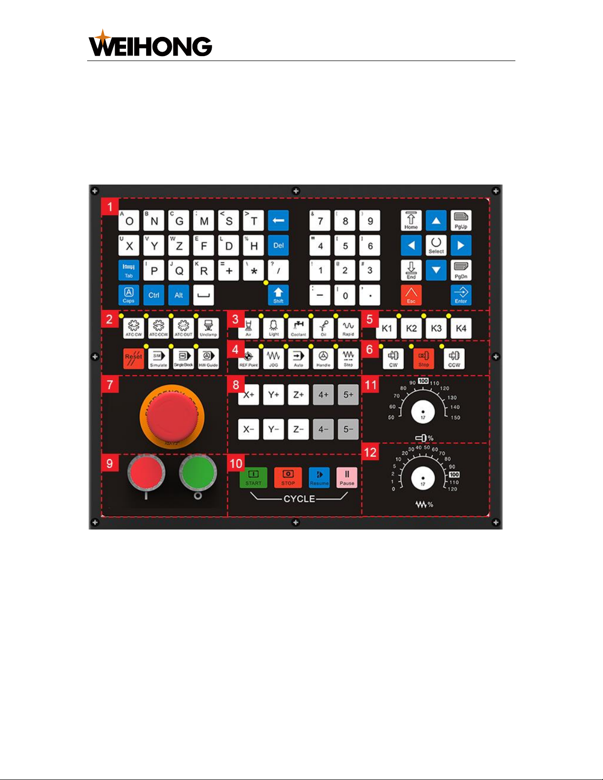
Including ATC CW, ATC CCW, ATC OUT, Unclamp, Reset, Simulate, Single
Block and HW Guide keys.
3. Keys for common ports
Used to turn on / off frequently used ports.
Including Air, Light, Coolant, Oil keys, and control rapid movement, including
Rapid key.
4. Keys for mode selection
Used to select a machining mode among REF.Point, JOG, Auto, Handle and
Step.
JOG, Handle and Step modes are referred as Manual mode.
5. Extension keys
Used to customize extension functions.
Including K1, K2, K3 and K4 keys.
In Integrated CNC System for Shoe Molding Machines, K1 key is used as an
air brake key for frock clamp. Before each machining, the system will judge
whether the fixture is clamped. Only when it is clamped, the system will start
machining. Otherwise, a yellow alarm occurs.
6. Keys for spindle control
Used to control the spindle movement, including CW, Stop and CCW keys.
7. E-stop switch
Used to stop the movement of the machine tool when the machine tool is in
danger, so as to protect the operator and machine tool.
After danger is cleared, you can rotate the switch clockwise to remove the E-
stop alarm.
8. Keys for axis direction
Used to manually move each axis.
In Manual mode:
–Press an axis direction key and Rapid key at the same time. The axis
moves at rapid jog speed.
–Press an axis direction key. The axis moves at jog speed.

上海维宏电子科技股份有限公司
SHANGHAI WEIHONG ELECTRONIC TECHNOLOGY CO., LTD.
7/ 29
9. Power Switch
Used to control power on or off.
10. Keys for movement control
Used to control the movement of the machine tool.
Including START, STOP, Pause, and Resume keys.
11. Spindle override knob
Used to adjust spindle override from 50% to 150%.
When parameter N72003 G00 F Fixed is set to No, the knob is used as G00
override knob and used to adjust G00 override from 0% to 100%.
12. Feed override knob
Used to adjust feed override from 0% to 120%.

上海维宏电子科技股份有限公司
SHANGHAI WEIHONG ELECTRONIC TECHNOLOGY CO., LTD.
8/ 29
1.2.2 Mounting Dimension (Unit: mm)
WH108C Dimension
WH108C Cut-out

上海维宏电子科技股份有限公司
SHANGHAI WEIHONG ELECTRONIC TECHNOLOGY CO., LTD.
9/ 29
1.3 Main Software Interface
The interactive user interface for NcStudio Software for Shoe Molding Machines
in Auto mode is as follows:
1. Status bar
It shows the following information:
–Current mode, such as Auto, JOG, etc.
–Current status of the machine tool, such as RUN, IDLE, etc.
–Name of the loaded program file.
–Machining time.
2. Information bar
It shows information, such as machining process, alarms, etc.
3. Functional area
It shows child interfaces corresponding to each main functional keys.
4. Functional keys
It show commands corresponding to F1 ~ F8 operation keys.
It differs with the child interfaces.

上海维宏电子科技股份有限公司
SHANGHAI WEIHONG ELECTRONIC TECHNOLOGY CO., LTD.
10 / 29
2Quick Start
Through this section, you can quickly know the following machining processes for
Integrated CNC System for Shoe Molding Machines:
1. Load a program file.
2. Select tools for machining.
3. Execute selective machining.
4. Do the related setting for machining.
5. Adjust the WCS.
6. Calibrate after tool changed.
2.1 Load a Program File
A shoe mold has multiple faces, and each face corresponds to a program file.
To load program files, do one of the following:
•To machine one face of a shoe mold, load a program file from the following path:
–The host: Program files saved in the root directory of the host
D:\\NcFiles.
–A USB flash disk: Program files saved in the root directory and
subdirectory of the USB flash disk.
–The internet: Program files saved in the host or the network.
It is similar to load a program file from these three paths. This section takes
Load a Program File from the Internet as an example.
•To machine the whole shoe mold at a time, set a machining task and load all
program files.
2.1.1 Load a Program File from the Internet
This operation is used to establish network connection between the integrated CNC
system for shoe molding machine and PC, to realize two-way transmission between
them.
To load a program file from the internet, do the following:
1. Set the IP address.
2. Verify the connection.
3. Access a shared program file.

上海维宏电子科技股份有限公司
SHANGHAI WEIHONG ELECTRONIC TECHNOLOGY CO., LTD.
11 / 29
2.1.1.1 Set the IP Address
This operation is used to establish the network connection channel between the
integrated CNC system and the PC by automatically obtaining or manually setting
the IP address.
It is default to automatically obtain the IP address. And this operation takes
manually setting the IP address as an example.
Before setting the IP address, ensure that the integrated CNC system and PC are in
the same subnet.
To manually set the IP address, do the following:
1. Press → 2→ F1. Network Setting dialog box pops up:
2. To not automatically obtain the IP address, press .
3. Press ↑or ↓to select the target input box, and set the following addresses:
–IP address
E.g. 192.168.1.188 (the first three digits should be the same with that of
PC, and the last digit should be different from that of PC)
–Subnet mask
It is the same with PC.
–Default gateway
It is the same with PC.

上海维宏电子科技股份有限公司
SHANGHAI WEIHONG ELECTRONIC TECHNOLOGY CO., LTD.
12 / 29
4. To close Network Setting dialog box and save the settings, press F7.
The new networking information shows in Network Connection Status area in
Computer interface.
2.1.1.2 Verify the Connection
This operation is used to verify whether the IP addresses are set successfully by
ping command after the IP addresses of the integrated CNC system and PC are set
well.
To verify the connection, do the following:
1. To open the command window, press Win and Rkeys on the keyboard of PC,
and input cmd in Run dialog box.
2. Input ping and IP address of the integrated CNC system.
e.g. ping 192.168.0.1
3. Press Enter, and check the result:
Connection succeeds, and network connection between the integrated CNC system
and PC is established.

上海维宏电子科技股份有限公司
SHANGHAI WEIHONG ELECTRONIC TECHNOLOGY CO., LTD.
13 / 29
If the connection fails, troubleshoot the following:
1. Check the corresponding cable interface of the router.
2. Check the physical connection and IP setting.
See Set the IP Address for details.
2.1.1.3 Access a Shared Program File
This operation is used to access a shared program file from PC or other integrated
CNC systems after network connection is established correctly.
If you access a folder from PC, before accessing a shared program file, set property
of the target folder as Shared.
To access a shared program file, do the following:
1. To enter Network interface, press → 3:

上海维宏电子科技股份有限公司
SHANGHAI WEIHONG ELECTRONIC TECHNOLOGY CO., LTD.
14 / 29
2. Press H. Browse for Folder dialog box pops up:
3. Select Network → the target PC, find the desired shared folder, and click OK.
File list in the shared folder shows in Network interface.
4. To select the target program file, press ↑or ↓.
5. To load the target program file for machining, press F1.
You can also do the following for a shared program file from the internet:
•F5: unload the loaded program file.
•F8: copy the target program file into the integrated CNC system.

上海维宏电子科技股份有限公司
SHANGHAI WEIHONG ELECTRONIC TECHNOLOGY CO., LTD.
15 / 29
2.1.2 Set a Machining Task
The system can automatically match the program files with technics and load all
matched program files at a time to improve efficiency.
To machine several faces of the shoe mold with one tool at a time, set the machining
task and then machine the shoe mold with the selected tool.
The default matching rules of program files with technics, workpiece coordinate
systems and A-axis coordinates are as follows:
Number
Technic
Program Name
WCS
A Coordinate
1
Inner
TOP
G54
A0
2
Bottom
BOT
G54
A0
3
Medial View
IN
G55
A0
4
Toe Cap
FN
G55
A90
5
Lateral View
OUT
G55
A180
6
Heel
BK
G55
A270
Before setting a machining task, ensure that parameter N80000 Support
Machining Tasks is set to Yes.
To set a machining task, do the following:
1. Press 1→ F3, and place the program files in the folder in the root directory of
the host.
Note: Files in the subdirectory of the host or from a USB flash disk and the internet cannot be read.

上海维宏电子科技股份有限公司
SHANGHAI WEIHONG ELECTRONIC TECHNOLOGY CO., LTD.
16 / 29
2. According to the actual situation, modify names of program files in the target
folder:
–If it is your first time to match the program files with technics, modify
the names according to the default matching principle.
–If you have modified the matching principle, modify the program file
names according to your customized matching rules.
The system will automatically match program files with technics according to
the program file names.If Some program files are not matched and their
corresponding technics names turns to number in Technic column:
3. Optional: To adjust the machining order of technics, select the target technic
and press F4 / F5.
4. Optional: If you need to modify the default setting of the target technic, do the
following:
1. Select the target technic and press F6.
2. Modify the following according the actual situation:
•To modify the matched technic name, press F1.
•To modify the matched name of program file, press F2.

上海维宏电子科技股份有限公司
SHANGHAI WEIHONG ELECTRONIC TECHNOLOGY CO., LTD.
17 / 29
•To modify the workpiece coordinate system, press F3.
The supported workpiece coordinate system includes coordinate
systems G54 ~ G59 and extended coordinate systems G54P0 ~
G54P119. Before using extended coordinate systems, ensure
parameter N80010 Support Extended Part Offsets is set to Yes.
•To modify the A-axis coordinate, press F4.
5. After modification, click Save.
2.2 Select Tools for Machining
This operation is used to select the target tools to machine the target parts of the
workpiece when several tools exist in the program file and each tool is used to
machine different parts.
It is only effective to G code and ENG files.
To select tools for machining, do the following:
1. To enable tool selection, press → 1→ F2, check and modify the value
of one of the following parameters to Yes:
–If you need to load a G code file, modify parameter N62022 Enable
Tool Selection for G Code File.
–If you need to load an ENG file, modify parameter N65203 Enable Tool
Selection for ENG File.

上海维宏电子科技股份有限公司
SHANGHAI WEIHONG ELECTRONIC TECHNOLOGY CO., LTD.
18 / 29
2. To load a G code or an ENG program file, press and select paths of
program files in Prog interface.
Select Tool for ENG/G File dialog box and Coor interface show:
See Load a Program File for how to load a program file.
3. To select the target tools for machining, press ↑/ ↓→ F1 repeatedly until all
target tools are added.
You can select one tool or more. And all tools are selected by default.
4. To save the setting, press F7.
After selecting tools for Machining, do one of the following:
•To select a tool again, do the following:
1. In Auto mode, to open Select Tool for ENG/G File dialog box,press
→ 1→ F4.
2. Select the target tool.
•To check the information about all tools in a G code file, press F8 to enter Tool
List interface.
You can do it during machining.
Other manuals for NK300CX
2
This manual suits for next models
1
Table of contents
Popular Industrial Equipment manuals by other brands

Bosch
Bosch Rexroth PS5000 Comissioning, Operating Instructions

MORLEY
MORLEY M30E owner's manual

Siemens
Siemens SIMATIC HMI Product information

PCB Piezotronics
PCB Piezotronics ICP 320C15 Installation and operating manual

Dantel
Dantel 46512 Installation & operation manual

Leroy-Somer
Leroy-Somer LSA 46.2 Installation and Maintenance

Honeywell
Honeywell COMBISAFE manual

Maxon
Maxon EC frameless DT installation manual

Graziadio & C.
Graziadio & C. K Series Assembly instructions

Siemens
Siemens 3TS1722-0A 5-8K Series operating instructions

Grundfos
Grundfos MG Series Installation and operating instructions

Starlight Xpress
Starlight Xpress Mini Filter Wheel with OAG Handbook