Burkert 8741 User manual

Operating Instructions
Bedienungsanleitung
Manuel d‘utilisation
Type 8741, 8742
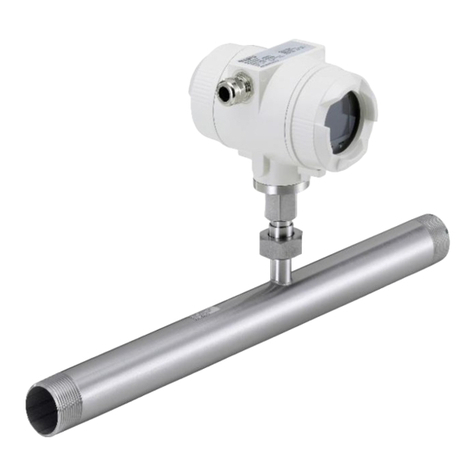
büS/CANopen
Mass Flow Meter (MFM) / Mass Flow Controller (MFC)
Massendurchflussmesser (MFM) / Massendurchflussregler (MFC)
Débitmètre massique (MFM) / Régulateur de débit massique (MFC)

We reserve the right to make technical changes without notice.
Technische Änderungen vorbehalten.
Sous réserve de modifications techniques.
© Bürkert SAS, 2014–2022
Operating Instructions 2206/05_EU-ML_00810383 / Original EN

3
Table of contents
Type 8741 / 8742
1 OPERATING INSTRUCTIONS............................................... 5
1.1 Denitionofterms ........................................................ 5
1.2 Symbols used............................................................... 5
2 INTENDED USE .................................................................... 6
2.1 Versions with explosion protection............................... 6
3 BASIC SAFETY INFORMATION............................................ 7
4 GENERAL INFORMATION .................................................... 8
4.1 Manufacturer’s name, manufacturer’s address
and international contacts............................................ 8
4.2 Warranty ....................................................................... 8
4.3 Information on the Internet ........................................... 8
5 DESCRIPTION OF THE DEVICE........................................... 9
5.1 Design of the device..................................................... 9
5.2 General description .................................................... 10
5.3 Operation of the MFM (Mass Flow Meter).................. 10
5.4 Operation of the MFC (Mass Flow Controller) ............ 10
5.5 Operation of the sensor in the device ........................ 12
6 TECHNICAL DATA............................................................... 13
6.1 Conformity.................................................................. 13
6.2 Standards ................................................................... 13
6.3 Certication ................................................................ 13
6.4 Operating conditions .................................................. 13
6.5 Mechanical data ......................................................... 14
6.6 Fluid data.................................................................... 14
6.7 Electrical data............................................................. 15
6.8 Markings..................................................................... 16
7 INSTALLATION.................................................................... 17
7.1 Safety instructions...................................................... 17
7.2 Before installation....................................................... 18
7.3 Mechanical installation ............................................... 18
7.4 Fluid system installation ............................................. 18
7.5 Installation and removal of the impact pro-
tection cover and blind plug on type 8742................. 20
7.6 Settinguptheeldbus ............................................... 21
7.7 Electrical installation................................................... 23
7.8 Connecting the functional earth ................................. 25
7.9 Connecting the cable screen...................................... 26
8 COMMISSIONING............................................................... 26
8.1 Safety instructions...................................................... 26
9 OPERATION AND FUNCTION ............................................ 27
9.1 Safety instructions...................................................... 27
9.2 Normal control mode.................................................. 27
9.3 Device status LED ...................................................... 27
9.4 Settinguptheeldbus ............................................... 28
9.5 Replaceablecongurationmemory............................ 28
9.6 Functions .................................................................... 30
English

4
Type 8741 / 8742
10 MAINTENANCE................................................................... 34
10.1 Maintenance for operation with heavily con-
taminated media......................................................... 34
10.2 Cleaning and recalibration at the factory.................... 35
11 DEVICE STATUS/TROUBLESHOOTING............................. 36
11.1 Display of the device status ....................................... 36
11.2 Troubleshooting.......................................................... 38
12 ACCESSORIES /SPARE PARTS......................................... 39
12.1 Electrical Accessories................................................. 39
12.2 Fluid accessories........................................................ 40
12.3 BürkertCommunicator(PCsoftware) ........................ 40
12.4 Additional documentation .......................................... 41
12.5 Spare parts ................................................................. 41
13 DECOMMISSIONING.......................................................... 41
13.1 Safety instructions...................................................... 41
13.2 Dismantling the device ............................................... 42
14 TRANSPORT, STORAGE, DISPOSAL................................. 43
15 RETURNING THE DEVICE.................................................. 43
English

5
Operating instructions
Type 8741 / 8742
1 OPERATING INSTRUCTIONS
The Operating Instructions describe the entire life cycle of the
device. Please keep the Operating Instructions in a safe place,
accessible to all users and any new owners.
Important safety information!
Please read the manual carefully. Pay particular attention to the
sections 3 Basic safety information and 2 Intended use.
▶The Operating Instructions must be read and understood.
1.1 Denition of terms
The term "device" as used within the Operating Instruc-
tions,alwaysreferstotheMFM/MFCtype8741/8472with
büS/CANopendigitalcommunication.
1.2 Symbols used
The following symbols are used in these instructions.
DANGER!
Warns of immediate danger!
▶If ignored, death or serious injury will result.
WARNING!
Warns of a situation which is possibly dangerous!
▶If ignored, serious injury or death may result.
CAUTION!
Warns of possible danger!
▶Failure to observe this warning can result in substantial or
minor injuries.
NOTE!
Warns of damage to property!
Important advice and recommendations.
Refers to information in this operating manual, or in other
documents.
▶Indicates a risk prevention statement.
→Indicates a procedure that must be carried out.
Indicates a result.
MenuIdentiesatextofauserinterface.
English

6
Intended use
Type 8741 / 8742
2 INTENDED USE
Improper use of the device may be a hazard to people, nearby
equipment and the environment.
MFM type 8741/8742 is used exclusively to measure the mass
ow of clean dry gases.
MFC type 8741/8742 is used exclusively to control the mass
ow of clean dry gases.
▶Observe the additional data, operating and service conditions
speciedinthecontractdocuments,theOperatingInstructions
and on the name plate and calibration plate.
The device
▶Use only for the media indicated on the name plate and in
the calibration protocol.
▶only use indoors.
▶onlyuseuptoanaltitudeof2000m.
▶Use only in conjunction with external instruments and compo-
nents recommended by Bürkert.
▶Operate carefully and ensure regular, professional
maintenance.
▶Operate only in perfect working order and ensure appropri-
ate storage, transport, installation and control.
▶Use only for its intended purpose.
2.1 Versions with explosion protection
DANGER!
Danger of explosion in the event of improper use in poten-
tially explosive areas!
▶Observethespecicationsoftheconformitycerticate.
▶ForEx.certiedversions,thespecicationsintheATEXsup-
plement for type 8742 available at country.burkert.com must
be observed.
2.1.1 Ex. certication
TheEx.certicationisonlyvalidiftheBürkertdeviceisusedas
describedintheATEXsupplement.
Ifunauthorizedchangesaremadetothedevice,theEx.certication
becomes invalid.
English

7
Basic safety information
Type 8741 / 8742
3 BASIC SAFETY INFORMATION
These safety instructions do not take the following into account:
• any contingencies or occurrences that may arise during instal-
lation, use and maintenance.
• Location-specicsafetyregulations,adherencetowhich,also
on the part of the mounting personnel, is the responsibility of
the operator.
Danger due to high pressure in the installation/device.
▶Before working on the installation or device, cut the pressure
and vent and drain the pipes.
Risk of injury from electric shocks.
▶Before working on the installation or device, switch o the
power and ensure that it cannot be reactivated.
▶Observe the applicable accident protection and safety regu-
lations for electrical equipment!
Burns/re hazard due to hot surface of the device!
▶Keepthedeviceawayfromanyhighlyammablematerials
or media and avoid any contact with bare hands.
Danger due to escape of the medium.
▶Observe the applicable accident protection and safety regu-
lations relating to the operating medium used.
Various dangerous situations.
To avoid personal injury, take care:
▶Not to operate the device without the factory installed input
lters.
▶Only to operate the device in the installation position given
on the calibration plate.
▶That the operating pressure of the device is not higher than
the maximum calibration pressure (MFM) specied on the
calibration plate or the tightness pressure of the proportional
valve (MFC).
▶Toonlyusethedeviceforthemediumspeciedastheoperating
medium in the calibration protocol.
▶Only to use agents that are stable with the device materials
for cleaning and decontamination
The compatibility chart can be found on our homepage:
country.burkert.com.
In the event of any ambiguity please contact your local sales
oce.
▶Donotmakeanymodicationstothedeviceanddonotsubject
the device to mechanical loads.
▶Protect the installation/device from accidental actuation.
▶Only trained personnel may perform installation and mainte-
nance work.
▶After an interruption in the electrical and media supply, ensure
a controlled restart of the process.
▶Observe best industry practice.
English

8
General information
Type 8741 / 8742
NOTE!
Components / assemblies at risk from electrostatic charges!
The device contains electronic components which are susceptible
to electrostatic discharge (ESD). Contact with electrostatically
charged persons or objects endangers these components. In
the worst case, they will become defective immediately or will
fail when energized.
• To minimise or even avoid all damage due to an electro-
static discharge, take all the precautions described in the
EN61340-5-1.
• Do not touch any of the live electrical components.
4 GENERAL INFORMATION
4.1 Manufacturer’s name,
manufacturer’s address and
international contacts
The name of the manufacturer is displayed as inset writing on the
cover and the housing of the device.
The manufacturer of the device can be contacted at the following
address:
Bürkert SAS
Rue du Giessen
F-67220 TRIEMBACH-AU VAL
Theaddressesofourinternationalsalesocesareavailableon
the internet at: country.burkert.com.
4.2 Warranty
The warranty is conditional on compliant use of the device in
observanceoftheoperatingconditionsspeciedinthismanual.
4.3 Information on the Internet
Operating manuals and data sheets for the type 8741/8742 can be
found online at: country.burkert.com.
English

9
Description of the device
Type 8741 / 8742
5 DESCRIPTION OF THE DEVICE
5.1 Design of the device
Connector*
for electrical con-
nection (4-pin screw
terminals)
Functional earth con-
nection:
M3 screw**
M4 screw**
Fluid connection
Flow direction
LED to display
the device status
(according to
NamurNE107)
Conguration
memory
Setting
Fieldbus
* The removable connector is part of the device
** For cable shielding and earthing of the device
Fig. 1: Design of the device type 8741
34 567
91011
8
21
büS ↔CAN
1. Congurationmemory
2. Settingoftheeldbus
3. Mounting screws
4. Impactprotectioncover(onlynecessaryonATEXversions)
5. M12sealingcap(onlyATEXversions)
6. Blindplug(accesstothecongurationmemoryandeldbus
switch)
7. Connector (counterpart is not part of the device) for
electrical connection (5-pin M12 plug)
8. LED to display the device status (according to NAMUR
NE107)
9. Flow direction
10. Functional earth connection: M4-screw for cable shielding
and device earthing
11. Fluid connection
Fig. 2: Design of the device type 8742
English

10
Description of the device
Type 8741 / 8742
5.2 General description
The device is available in two basic versions.
• As a Mass Flow Meter (MFM) the device measures the mass
owofthegasesforwhichithasbeencalibrated.
• As a Mass Flow Controller (MFC) the device measures and
controlsthemassowofthegasesforwhichithasbeen
calibrated. In contrast to the MFM, the MFC also contains a
regulation valve. The gas must be in a dry and clean state.
Digital communication with the device (for example for transfer
of the setpoint or measured value) is achieved via CANopen*- or
büS**.
*CANopen-AeldbusbasedonCAN(ControllerArea
Network) that is used in automation technology for
networking of devices.
**BÜS-ACANopen-basedeldbuswithadditional
functionalities.
5.3 Operation of the MFM (Mass Flow
Meter)
AsensorisintegratedintotheMFMtomeasurethemassow.The
measured value is transmitted to an external device via a digital
output(eldbus).
5.4 Operation of the MFC (Mass Flow
Controller)
Design:
• Themassowismeasuredbyasensor.
• TheMFCisttedwithelectronicsandalow-frictionpropor-
tional valve with a high response sensitivity to control the mass
ow.
NOTE!
Malfunction due to contamination.
Forproblem-freefunctioningoftheMFC,altermustbe
installed in front of the device for contaminated operating
media.
Seechapter6.4.1 Quality of the operating medium.
Operation:
Thesensormeasuresthe mass ow and relays the measured
value to the integrated electronics. The electronics compares the
measured current value (x) with the desired setpoint value (w) and
calculates the control value to be transmitted to the proportional
valve (Y) in order to control its opening.
Themassowiseitherkeptstableataconstantvalueoraltered
accordingtoapredenedprole.
Theregulationisperformedindependentofpressureuctuationsor
increasedowresistance,suchasmightbecausedbydirtylters.
The short response time of the proportional valve and the dynamics
of the sensor determine the setting time.
English

11
Description of the device
Type 8741 / 8742
Themeasuredmassowvalueistransmittedtoanexternaldevice
viaadigitaloutput(eldbus).
In order to obtain a dynamic or quiet measured-value
output signal, the damping of this signal can be adjusted by
the"BürkertCommunicator"software.Seechapter12.3.
Function diagram:
w
xout
y
x
xd = w-x
Electronic
Sensor Proportional valve
Medium inlet
Medium outlet
Fig. 3: Function diagram of the MFC (Mass Flow Controller)
5.4.1 The MFC electronics
The electronics
• comparethemeasuredvalueofthemassowwiththespec-
iedsetpoint
• and controls the opening of the proportional valve.
Setpoint
Thesetpoint(w)istransmitteddigitallyviatheeldbusinterface.
Forcontrolofasystemwherequickow-ratechangesarenotper-
mitted, a ramp function can be activated. This enables the param-
eters for an ascending or descending setpoint to be set separately.
Control settings
The control settings are preset at the factory.
Amplicationfactors:
Afterstart-up,thecontrolleroperateswith amplication factors
dependent on the control-loop properties. The gain factors are
calculated automatically when the AUTOTUNE function is run. The
AUTOTUNE function enables the control settings to be optimised
for the installation's actual conditions.
Dynamic control parameters:
Thedynamicsforthecontrolloopofthedeviceisinuencedbytwo
settings, the gain (KP) and reset time (Tn). The dynamic control set-
tings can be adapted using the "Bürkert Communicator" software
(seechapter12.3BürkertCommunicator(PCsoftware)).
The extreme settings are:
1. A very quick regulation with the possibility of overshoots. The
controller reacts to even the smallest deviations. The control
maythencauseverystronguctuations.
2. A slow-acting regulation.
For less dynamic applications, the behaviour of the con-
troller may be damped. It then reacts slowly to very minor
uctuationsofthemeasuredvalueorset-point.
English

12
Description of the device
Type 8741 / 8742
Zero point shut-o:
A zero point shut-o is included to ensure the sealing function
of the valve. This is activated if the following conditions occur
simultaneously.
1.Setpoint<2%ofnominalowrateQnominal (with meas-
uring range 1:50)
2.Measuredvalue<2%ofnominalowrateQnominal (with
measuring range 1:50)
Ifthezeropointshut-oisactive,thePWMsignalisset
to0%sothatthevalveiscompletelyclosed.
5.4.2 MFC solenoid valve
NOTE!
The sealing function of the proportional valve cannot be
guaranteed for hard sealing materials.
Whenusedwithinthespeciedpressurerange,thepropor-
tionalvalvethatisusedforthemassowcontrolalsoprovides
the sealing function.
Exception:
If the seat seal is composed of a special, hard sealing material
(e.g. PCTFE), as for nominal valve diameters of 0.05 and 0.1
mm,thentheleakagerateoftheproportionalvalvemaydier
from that of a device with a soft seat seal (e.g. FKM or EPDM).
The maximum leak rate in both cases is 1 Nml/min (air).
A higher tightness may be possible, however it is not standard
and must therefore be requested.
The solenoid valve used for an MFC is a direct-acting, normal-
ly-closed proportional valve. The nominal diameter of the solenoid
valveisdeterminedbytherequirednominalow-rateQnominal, the
pressure conditions in the process and the density of the operating
medium.
5.5 Operation of the sensor in the
device
The integrated ow-rate sensor in the device use the thermal
measurement process (anemometric and calorimetric) to measure
themassow.Thisessentiallyconsistsofaheatingresistorand
atemperatureprobe.Theoperatingmediumwhichowsthrough
thedevicemodiesthetemperaturedierencemeasuredbetween
the two resistors.
The thermal measurement principle allows the MFC to control
therequiredmassowalmostindependentlyofthepressureand
temperatureuctuationsintheapplicationconcerned.
English

13
Technical data
Type 8741 / 8742
6 TECHNICAL DATA
6.1 Conformity
The device complies with the EU-directives according to the EU
declaration of conformity (if applicable).
6.2 Standards
The standards used to demonstrate conformity with the Directives
canbeconsultedintheEUtypeexaminationcerticateand/orthe
EU declaration of conformity (if applicable).
6.3 Certication
Aversionofthedevicetype8742iscertiedinaccordancewith
ATEXdirective94/9/ECforcategory3GDforuseinZone2.
InstructionsforuseinEx.areas(seeadditionalATEX
instructions at country.burkert.com).
6.4 Operating conditions
WARNING!
Risk of injury from malfunction due to outdoor use!
▶Do not use the device in outdoor areas.
SpecialoperatingconditionswithATEXcertication:Seethe
ATEXsupplementforthetype8742.
Permissible temperatures
Ambienttemperature: −10°C...+50°C
Mediumtemperature: −10°C...+70°C
foroxygen: −10°C...+60°C
Permissiblehumidity: <95%,non-condensing
Protection class Type 8741: IP20
Type 8742: IP65 1)+IP671)
if device properly wired and con-
nectors inserted and tightened
Operatingpressure: Max.10bar(dependingonthe
nominal diameter of the proportional
valve)
WARNING!
Risk of injury caused by pressure, medium escape!
Importantdevice-specicdataareindicatedonthenameplate
and calibration plate.
▶Onlyusethedeviceforthespeciedoperatingmedium.
▶Donotexceedthespeciedcalibrationpressure.
1) Protection ratings IP65 and IP67 have not been evaluated according to
UL61010butdeterminedbyBürkert.
English

14
Technical data
Type 8741 / 8742
6.4.1 Quality of the operating medium
For the required measurement and control precision and to meet the
safety requirements, the gas or gas mixture must meet the following
quality criteria according to standard ISO 8573-1 (Compressed
Air-Part1:Contaminantsandpurityclasses):
Maximumparticlesize: Class2: 1µm
Maximumparticledensity Class2: 1mg/m³
Maximumdewpointunderpressure:Class4: 3°C
Maximumoilconcentration Class1: 0.01mg/m³
ForfurtherinformationseeISO8573-1.
Other hazardous gases are possible on demand; under normal
operating conditions the devices do not release any gas.
6.5 Mechanical data
Dimensions: See datasheet
Weight: See datasheet
Materials:
Base block Aluminium or stainless steel 1.4305
Housing: Type 8741: Polycarbonate (PC)
Type 8742: Die-cast aluminium, painted
Sealing material: See name plate
Other materials of the proportional
valve in contact with the medium: 1.4310, 1.4113, 1.4305
6.6 Fluid data
Calibration medium Operatinguidorair
Mass flow range
(reference to N2 (IN/min)
0.01...80
Measurement
accuracy
±0.8%*ofthemeasuredvalue
±0.3%*ofthefullscale
(after 1 minute warm-up time)
Measurement range/
control range
1:50**
**Largermeasuringrangeavailableon
request.
Repeataccuracy:±0.1%offullscale
deflection
Operating medium See name plate
(quality classes according to
DINISO8573-1,seechapter6.4.1).
*If the operating uid is dierent from the calibration uid, the actual
measurement accuracy might vary from the value stated in the data
sheet. If the operating uid is natural gas, the measurement accuracy
depends on the composition of the natural gas, which can vary
depending on the origin and season.
6.6.1 Pressure loss diagram
The diagram shows an example of the compressed air loss for air
ow.
The two air pressure curves on the diagram are examples for the
design/device variants.
• ¼inchpipeconnectionand
English

15
Technical data
Type 8741 / 8742
• angeconnectiononthebottomofthedevice(usedfor
mounting on a block).
0
10
20
30
40
50
60
70
80
90
100
110
120
130
0510 15 20 25 30 35 40 45 50 55 60 65 70 75 80
Q [l
N
/min]
∆p [mbar]
Flange
1/4''
Fig. 4: Pressure loss diagram, for air, with a 250µm input lter,
for an MFM
For other operating gases, the pressure drop pair can be read
fromthegraphasafunctionoftheowrateQair. For the same
owrateoftheoperatinggasQGas = Qair the pressure drop can
be evaluated using the formula:
ρ
ρ
air air
Under the root are the densities of the operating gases and of air
inthenormalstateaccordingtoDIN1343(PN=1013.25mbar,
TN=273.15K).
6.7 Electrical data
Operating voltage
MFC: 24VDC±10%;
residualripple<2%
MFM: 24VDC±10%
Max. power consumption
MFM : <1W
MFC: Dependent on the proportional
valve used, see name plate in
chapter6.8.2
Communications interface: büS or CANopen
LEDs: 1 LED
accordingtoNamurNE107*
Electricalconnections: Type8741:4-pinterminals,5.08mm
grid
Type 8742: Round plug connector,
M12 plug, 5-pin, coding A
* NAMUR recommendations (NE) 107: self-monitoring and diagnosis of
eld devices.
Standards committee for measurement and control technology
(NAMUR) is an international association of users of automation systems
for the process industry.
English

16
Technical data
Type 8741 / 8742
6.8 Markings
WARNING!
Risk of injury caused by pressure, medium escape!
Importantdevice-specicdataareindicatedonthenameplate
and calibration plate.
▶Onlyusethedeviceforthespeciedoperatingmedium.
▶Donotexceedthespeciedcalibrationpressure.
6.8.1 Calibration plate
Type of the device
Calibration medium
Calibration pressure
Device order code
Installation position
Calibration date
Fig. 5: Location and description of the calibration plate
6.8.2 Standard name plate
8741 24V ... 9W [5,5W]
IP20 NEC Class 2 only
5,0 Nl/min Air
10,0 Nl/min Air
büS/CANopen
GR:1 KL:A Ta=-10°C..+50°C
S/N 1000 W41ME PS=100barg EPDM
00******
12 3
4
5
6
7
810
11
9
12
13
14
15
16
1. Type of the device
2. Supply voltage, direct current
3. ConsumptionaccordingtoUL61010-1[typical
consumption1)]
4. Warning symbol: observe the Operating Instructions deli-
vered with the device.
5. Ambient temperature
6. Sealing material
7. Burst pressure
8. Manufacturing code
9. Class of the valve (according to the DVGW 2))
10. Device order code
1) Conditions:ambienttemperature23°C,nominalowrate
100%,regulationfor30minutes
2) DVGW = Deutscher Verein des Gas- und Wasserfaches
English

17
Installation
Type 8741 / 8742
7 INSTALLATION
7.1 Safety instructions
DANGER
Danger due to high pressure in the installation/device.
▶Before working on the installation or device, cut the pressure
and vent and drain the pipes.
Risk of injury from electric shocks.
▶Beforeworkingontheinstallationordevice,switchothe
power and ensure that it cannot be reactivated.
▶Observe the applicable accident protection and safety regu-
lations for electrical equipment.
Risk of injury from medium escape.
▶Observe the applicable accident protection and safety regu-
lations relating to the operating medium used.
WARNING!
Danger of injury from improper installation!
▶The installation must only be carried out by trained personnel
using suitable tools.
▶Secure the system against unintentional actuation.
▶Ensure a controlled restart after installation.
11. Serial number
12. Category of the device
13. Communication interface
14. Nominalowrate(Qnominal),unitsandoperatingmediumgas2
15. Nominalowrate(Qnominal),unitsandoperatingmediumgas1
16. Protection rating
Fig. 6: Description of the name plate
6.8.3 Additional marking
Rue du Giessen
F-67220 Triembach
Made in France
Conformity marking
Certication
Fig. 7: Description of the additional marking
Find the description of the older markings on the device
in the supplement at country.burkert.com.
English

18
Installation
Type 8741 / 8742
Sequence of steps for installing the device:
1. Mechanical installation
Observe the installation position!
2. Fluid system installation
3. Fieldbus setting
Theeldbusispresetatthefactory.
Changes to this setting should be performed before the
electricalinstallation.Theswitchforsettingtheeldbus
isdiculttoaccessaftertheelectricalinstallation.
3. Electrical installation
Ensurethepowersupplyhassucientoutput!
7.2 Before installation
→Beforeinstallationoftheuidconnectionstothedevice,
removealldirtfromthepipesanduidcarryingcomponents
of the system.
→Installasuitablelterinfrontofthedevice(meshsize≤25µm)
to ensure the cleanliness of the operating medium.
7.3 Mechanical installation
Observe the installation position given on the calibration plate or
in the calibration protocol.
7.4 Fluid system installation
DANGER!
Danger due to high pressure in the installation/device.
▶Before working on the installation or device, cut the pressure
and vent and drain the pipes.
Selecttheuidconnectionsaccordingtothemaximummassow
rate. No inlet section is required.
Onrequest,thedevicecanbesuppliedwiththeuidconnections
tted.
WARNING!
Danger due to leakage!
Atlowmassowsandhighpressures,particularattention
must be paid to the tightness of the system in order to prevent
incorrect metering or leakage of the operating medium.
To ensure a secure seal
▶Installthettingswithoutsubjectingthemtoanystresses
▶Usecompressionttingstoensuresealingofthesystem.
▶Use a pipe with a suitable diameter and a smooth surface.
Procedure:
Theuidconnectionwas,asanexample,declaredrelatingtothe
front of the device but also applies to the connection on the rear
of the device.
English

19
Installation
Type 8741 / 8742
→Cutthelinesquarely[1]anddeburr[2].
1
2
Fig. 8: Cutting the pipe and deburring
→Remove the protective cap with which the port is closed.
→Slidetheunionnut[A] and then the clamping ring onto the
line.
A
Clamping
ring BC
Fig. 9: Slide the union nut and clamping ring onto the pipe.
→Fixthesealingring[C]andtheconnectingthread[B] to the
device(tighteningtorque25...28Nm).
CB
Fig. 10: Fix the sealing ring and screw on the connecting thread
→Insertthelineandtightentheunionnut[A] by hand.
A
Fig. 11: Insert pipe and tighten the union nut.
English

20
Installation
Type 8741 / 8742
→Tighten the lock nut with an open-end spanner so that the
connectionisleaktight(tighteningtorque25...28Nm).
Fig. 12: Tighten the union nut.
Nowmaketheuidconnectiontothebackofthedeviceinthe
same way.
7.5 Installation and removal of the
impact protection cover and blind
plug on type 8742
The impact protection cover is designed for use in an Ex. area. When
the device is used in a non-Ex. area, use of the impact protection
cover may be omitted.
The impact protection cover must be removed for the electrical
installation.Tochangetheeldbussettingortoreplacethecon-
gurationmemory,alsoremovetheblindplug.
Procedure:
→Loosen the 2 mounting screws.
→Remove the impact protection cover.
→Unscrew the blind plugs with a suitable tool (e.g. a screw-
driver) by turning it anti-clockwise.
→Changetheeldbussetting(seechapter7.6) or replace the
congurationmemory(seechapter9.5.1).
→Screw the blind plug clockwise using a tool (e.g. a
screwdriver)(atatorquebetween0.6Nm...0.8Nm,i.e.
0.44lbf·ft...0.59lbf·ft).
→Maketheelectricalconnection(seechapter7.7).
→Attach the impact protection cover
The locking hook of the impact protection cover must lie in
the notch of the housing.
English
Other manuals for 8741
1
This manual suits for next models
1
Table of contents
Other Burkert Industrial Equipment manuals

Burkert
Burkert buS User manual

Burkert
Burkert 6516 User manual

Burkert
Burkert PTB 14 ATEX 2023 X User manual

Burkert
Burkert BBS-03 User manual

Burkert
Burkert 8200 Series User manual

Burkert
Burkert 8644 AirLINE User manual

Burkert
Burkert 8681 User manual

Burkert
Burkert AC19 User manual

Burkert
Burkert 6519 User manual

Burkert
Burkert 8695 Series User manual