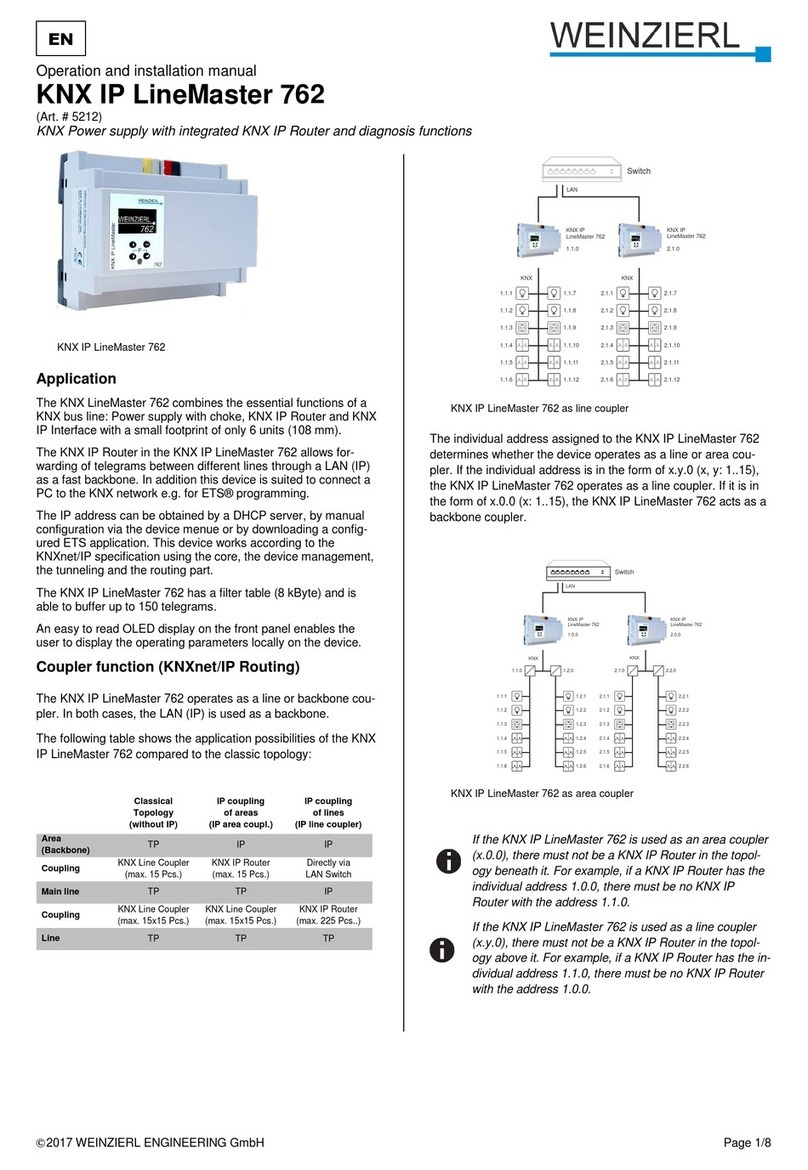
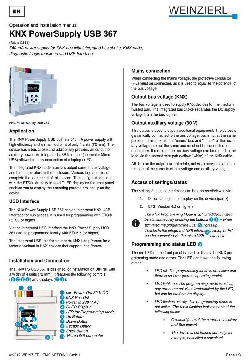
Weinzierl KNX IP LineMaster 762.1 secure Specification sheet

WEINZIERL ENGINEERING GmbH
Achatz 3-4
84508 Burgkirchen an der Alz
GERMANY
Tel.: +49 8677 / 916 36 –0
E-Mail:info@weinzierl.de
Web: www.weinzierl.de
© 2022 WEINZIERL ENGINEERING GmbH Seite 1/38
KNX power supply 640 mA with KNX IP router
KNX IP LineMaster 762.1 secure
Operation and installation manual
(Art. # 5465)

© 2022 WEINZIERL ENGINEERING GmbH Seite 2/38
Content
1Application .........................................................................................................................3
2Installation and connection...............................................................................................3
2.1 KNX programming mode......................................................................................................4
2.2 Manual operation and status display (device display)...........................................................4
3Reset to factory default settings.....................................................................................12
3.1 Factory default settings......................................................................................................12
4Wiring scheme .................................................................................................................13
4.1 Function as coupler (KNXnet/IP routing)............................................................................13
4.2 Function as bus access (KNXnet/IP tunneling)...................................................................16
5KNX Security.................................................................................................................... 16
6Interface settings in the ETS........................................................................................... 17
6.1 ETS 5.................................................................................................................................17
6.2 ETS 6.................................................................................................................................18
6.3 Common............................................................................................................................19
7Programming....................................................................................................................20
7.1 Via KNX bus ......................................................................................................................20
7.2 Via KNXnet/IP tunneling.....................................................................................................20
7.3 Via KNXnet/IP routing........................................................................................................20
7.4 Via direct IP connection .....................................................................................................20
8ETS database ...................................................................................................................22
8.1 Secure commissioning....................................................................................................... 22
8.2 Secure group communication............................................................................................. 24
8.3 Additional individual addresses..........................................................................................26
8.4 IP settings..........................................................................................................................27
8.5 Description.........................................................................................................................30
8.6 General settings.................................................................................................................30
8.7 Routing (KNX -> IP)........................................................................................................... 31
8.8 Routing (IP -> KNX)...........................................................................................................34
8.9 Filter Table.........................................................................................................................36
9Open source licenses...................................................................................................... 37

© 2022 WEINZIERL ENGINEERING GmbH Seite 3/38
1 Application
The KNX LineMaster 762.1 secure combines the essential functions of a KNX bus line: KNX power
supply with choke, KNX IP router and KNX IP interface. In addition to the bus voltage the power
supply offers an auxiliary voltage.
The KNX IP router in the KNX IP LineMaster 762.1 secure allows forwarding of telegrams between
different lines through a LAN (IP) as a fast backbone. Using the embedded KNX IP interface, the
KNX line can be connected directly to a PC (e.g. by ETS). The device supports KNX Security
which can be enabled in ETS. As secure router the device allows coupling of not secured
communication on KNX TP to a secured IP backbone. Also for the interface functionality
(tunneling) KNX security prevents from unauthorized access. The IP address can be obtained by a
DHCP server or by manual configuration (ETS) respectively.
This device works according to the KNXnet/IP specification using the core, the device
management, the tunneling and the routing part. The KNX IP LineMaster 762.1 secure has an
extended filter table for main groups 0 to 31 and is able to buffer up to 150 telegrams.
2 Installation and connection
The KNX IP LineMaster 762.1 secure is designed for installation on a DIN rail (35 mm) with a width
of 6 units (108 mm). It features the following controls and displays:
❶Auxiliary voltage 30 V⎓output
❷KNX bus connector
❸OLED display
❹Button up
❺Button down
❻Button escape
❼Button enter
❽Programming LED (red)
❾LAN connector
❿Supply voltage 230 V∿input
The device configuration can be done as follows:
▪Via the device display (partially).
▪With the ETS (version 5.7 or newer)

© 2022 WEINZIERL ENGINEERING GmbH Seite 4/38
2.1 KNX programming mode
The KNX programming mode is activated/deactivated either by simultaneously pressing the
buttons (P) ❺and ❼.
When the programming mode is active, the programming LED ❽lights up red.
2.2 Manual operation and status display (device display)
The red LED ❽on the front of the device is used to indicate KNX programming mode and errors.
Summary of the states of the programming LED ❽:
2.2.1 Startup and idle display
During startup of the device, the individual address and the state of the application is displayed.
The device name “KNX IP LineMaster” can be changed within ETS parameter settings.
The state can take one of the following values:
▪Running: The application is loaded and running.
▪Stopped: The application is stopped (programming LED ❽flashes)
▪Unloaded: The application is not loaded (programming LED ❽flashes)
▪Loading: The application is being loaded by the ETS
▪Overload: The output current exceeds the overload threshold 900 mA
(programming LED ❽flashes)
LED Status
Meaning
LED lights red
The programming mode is active.
Errors are not shown by the LED, but can be read in the display.
LED flashes red
Error conditions:
▪Overload (sum of current from auxiliary and
bus voltage output).
▪The device is not loaded correctly
e.g. after aborting a download.
The programming mode is not active.
LED is off
The device operatres in normal operating mode.
No error condition is active.
The programming mode is not active.

© 2022 WEINZIERL ENGINEERING GmbH Seite 5/38
▪Manual: Parameterized coupler settings were overwritten manually via manual operation in
the device display (filter, retransmit and acknowledge). A long press on button enter ❼
restores the normal operating mode as parameterized.
The power supply function (KNX –and auxiliary voltage) is independent of the state of the
application.
After 10 minutes of no activity, the device switches to the screen saver (blank screen
with a jumping dot) to increase the lifetime of the display. Pressing any key turns the
display back on.
2.2.2 Main menu
Pressing the button down ❺calls up the main menu of the device. By pressing button enter ❼
you call up the submenus. Within the menus, use buttons up ❹and down ❺to navigate, the
button enter ❼to confirm and the button escape ❻to go back or up one level.
The main menu offers the following menu items for selection:
▪Router
▪Powersupply
▪System Info
▪Dev Reset
▪Contrast
2.2.3 “Router” menu item
The Router menu item offers the following submenus for selection:
▪IP Config
▪IP Tunnel
▪Filter
▪Operation
▪Transit
▪Bus Errors

© 2022 WEINZIERL ENGINEERING GmbH Seite 6/38
2.2.4 “IP Config” submenu
Select DHCP or Manual for the IP configuration. Within Manual, you can set the IP, Subnet and
Gateway. Use buttons up ❹and down ❺to navigate and button enter ❼to select.
2.2.5 “IP Tunnel” submenu
The KNX IP LineMaster 762.1 secure supports 8 simultaneous KNXnet/IP tunneling connections.
In this submenu their current state and their individual KNX address are displayed.
2.2.6 “Filter” submenu
For commissioning or test purposes, the filter settings parameterized with the ETS can be
temporarily bypassed here. The settings for broadcast telegrams (BC), individual addressed
telegrams (IA) and group telegrams (GA0–main groups 0 to 13 and GA14 –main groups 14 to 31)
can be changed separately. The left side concerns the forwarding from the main line (IP) to the
subline (TP), the right side concerns the forwarding from the subline (TP) to the main line (IP).
The following selection options are available:
▪Forward: –
▪Block: x
▪Filter: \

© 2022 WEINZIERL ENGINEERING GmbH Seite 7/38
Settings that deviate from the parameterization are marked with a square bracket. The
parameterized setting can be restored with a long button press on button enter ❼.
2.2.7 “Rep / ACK” submenu
In this submenu the settings for repeating telegrams on the subline (TP) can be changed. The
settings for broadcast telegrams (BC), individual addressed telegrams (IA) and group telegrams
(GA) can be changed separately.
The following selections are available:
▪No repetition: ---
▪Up to 3 repetitions: REP
In addition, the settings for the telegram acknowledgement (acknowledge) on the subline (TP) can
be changed:
▪Confirm only when routing: ROUT
▪Always confirm: ACK
▪Negative confirmation: NACK
If the response is NACK, access to the device via KNX TP is no longer possible, see ETS
parameter settings.
These settings are temporary.
Settings that deviate from the parameterization are marked with a square bracket. The
parameterized setting can be restored with a long button press on button enter ❼.

© 2022 WEINZIERL ENGINEERING GmbH Seite 8/38
2.2.8 “Tel Counter” submenu
This submenu contains telegram counters. The number of forwarded telegrams can be read here
separately according to direction (main line IP to subline TP and vice versa) and telegram type
(individual addressed telegrams IA and group telegrams GA). The counters can be reset here.
2.2.9 “Bus Errors” submenu
In this submenu errors during KNX communication are displayed. By pressing button enter ❼the
error counters can be reset under the navigation item RESET COUNTERS.
The following errors are counted:
▪Send (error while sending)
Send failed after last retry because ACK, NACK or BUSY responses are missing.
▪Rcv (Error while receiving)
Deformed telegrams or telegram fragments received.
▪Repeat
Number of repeatedly sent or repeatedly received telegrams.
2.2.10 “Powersupply” menu item
The Powersupply menu item offers the following submenus for selection:
▪Diagnosis
▪History
▪Bus Reset
▪Ev Counter

© 2022 WEINZIERL ENGINEERING GmbH Seite 9/38
2.2.11 “Diagnosis” submenu
This menu displays the current values of busload (%), voltage (V), current (mA)
and temperature (°C).
The busload is a measure for the number of telegrams in a certain period of time.
100 % busload is reached at approx. 50 telegrams per second (Group Value Write
telegrams with 1 byte). The voltage shows the current value of the bus voltage, the
current the sum of bus and auxiliary current. The temperature is measured in the
device.
2.2.12 “History” submenu
The history shows the value range (min. and max.) for busload (%), voltage (V), current (mA) and
temperature (°C) of the last 24 hours.
Pressing button down ❺several times displays a graphical representation ("real time") for the
following values: Busload, voltage, current and temperature. The time span of each graph is
approx. 2 minutes.
To return to the main menu, press button escape button ❻.
2.2.13 “Bus Reset” submenu
In this submenu, the KNX line can be reset. By pressing button enter ❼the KNX bus voltage is
switched off. The maximum reset time is 30 seconds. This time can be shortened by pressing
button escape ❻.

© 2022 WEINZIERL ENGINEERING GmbH Seite 10/38
2.2.14 “Ev Counter” submenu
Various operating states are automatically logged in the device, which can be read in this
submenu. All times are displayed in the format “hours:minutes”.
▪Op. time [h:m]
Total summed up operating time of the device.
▪Run time [h:m]
Time since the last device restart.
The time restarts when the operating voltage is applied.
▪Restarts [count]
Number of device restarts.
The counter is incremented when the operating voltage is applied.
▪Time [h:m] > 75 °C
Summed operating time during which the temperature in the device was above 75 °C.
▪Time [h:m] > 640 mA
Summed operating time during which the current load was higher than 640 mA.
The current load of both outputs is recorded.
▪Time [h:m] > 900 mA
Summed operating time during which the current load was higher than 900 mA.
The current load of both outputs is recorded.
In order to extend the life of the internal memory, the values of the counters are stored
in the memory in a dynamic time span of up to 8 h. Thus, the values - if the power
supply to the device was interrupted - can fall back somewhat.

© 2022 WEINZIERL ENGINEERING GmbH Seite 11/38
2.2.15 “System Info” menu item
Information about the device is displayed here:
▪SerNo: Serial number
▪Info: ManufacturerID.AppID.AppVersion
▪State: State of the application
▪Vers.: Firmware version
▪MAC: MAC address
▪QR Code: KNX Security initial key (FDSK)
2.2.16 “Dev Reset” menu item
In this menu, the device can be restarted with RESTART DEVICE or reset to factory settings with
MASTER RESET. After selecting an option, button enter ❼must be held down until the animation
has finished and the option is executed.
After a master reset a new ETS download is required.
2.2.17 “Contrast” menu item
To adjust the contrast of the display, this menu item is selected in the main menu. By pressing
button enter ❼several times, the contrast can be set to different levels.

© 2022 WEINZIERL ENGINEERING GmbH Seite 12/38
3 Reset to factory default settings
It is possible to reset the device to its factory default settings (see “Dev Reset”menu item).
In the factory default settings, the device has the individual address 15.15.0 and no group
addresses are connected. The IP address assignment is done via DHCP. Also, KNX Security is
disabled and the initial key (FDSK) must be used for secure commissioning.
3.1 Factory default settings
Individual addresses, KNXnet/IP tunneling connections and IP address assignment
Individual address: 15.15.0
Active KNXnet/IP tunneling connections: 8
Individual address of tunneling connection 1: 15.15.240
Individual address of tunneling connection 2: 15.15.241
Individual address of tunneling connection 3: 15.15.242
Individual address of tunneling connection 4: 15.15.243
Individual address of tunneling connection 5: 15.15.244
Individual address of tunneling connection 6: 15.15.245
Individual address of tunneling connection 7: 15.15.246
Individual address of tunneling connection 8: 15.15.247
IP address assignment: DHCP

© 2022 WEINZIERL ENGINEERING GmbH Seite 13/38
4 Wiring scheme
4.1 Function as coupler (KNXnet/IP routing)
The KNX IP LineMaster 762.1 secure can work as line or area coupler. In both cases the LAN (IP)
is used as backbone.
The following table shows the possible applications of the KNX IP LineMaster 762.1 secure
compared to the classic topology:
Classic topology
(without IP)
IP coupling of the areas
(IP area coupler)
IP coupling of the lines
(IP line coupler)
Backbone
TP
IP
IP
Coupling
KNX TP line coupler
(max. 15 couplers)
KNX IP router
(max. 15 routers)
Directly via LAN with switch
Area
TP
TP
IP
Coupling
KNX TP line coupler
(max. 15x15 couplers)
KNX TP line coupler
(max. 15x15 couplers)
KNX IP router
(max. 225 routers)
Line
TP
TP
TP
The KNX IP LineMaster 762.1 secure has a filter table and thus contributes to the reduction of the
bus load. The extended filter table for main groups 0 …31 is automatically generated by the ETS.
Due to the difference in speed between Ethernet (100 Mbit/s) and KNX TP (9.6 kbit/s),
considerably more telegrams can be transmitted on IP. If several telegrams for the same line follow
each other shortly, they have to be buffered in the router to avoid telegram losses. For this
purpose, the KNX IP LineMaster 762.1 secure has memory space for 150 telegrams (from IP to
KNX TP).
The assignment of the individual address of the KNX IP LineMaster 762.1 secure determines
whether the device operates as a line or as an area coupler. If the individual address corresponds
to the form x.y.0 (x, y: 1 ... 15), the KNX IP LineMaster 762.1 secure functions as a line coupler. If
the individual address has the form x.0.0 (x: 1 ... 15), it is a area coupler.

© 2022 WEINZIERL ENGINEERING GmbH Seite 14/38
4.1.1 IP line coupler
If the KNX IP LineMaster 762.1 secure is used as line coupler (x.y.0), no KNX IP router
may be topologically above it. If, for example, a KNX IP router has the individual
address 1.1.0, there must be no KNX IP router with the address 1.0.0.

© 2022 WEINZIERL ENGINEERING GmbH Seite 15/38
4.1.2 IP area coupler
If the KNX IP LineMaster 762.1 secure is used as an area coupler (x.0.0), no KNX IP
router may be located topologically below it. If, for example, a KNX IP router has the
individual address 1.0.0, there must be no KNX IP router with the address 1.1.0.
4.1.3 IP area and line coupler

© 2022 WEINZIERL ENGINEERING GmbH Seite 16/38
4.2 Function as bus access (KNXnet/IP tunneling)
The KNX IP LineMaster 762.1 secure can be used as an interface to the KNX. The KNX bus can
be accessed from any point in the LAN. The device supports up to 8 simultaneous tunneling
connections. An additional individual address must be assigned for each connection. A more
detailed description can be found in the section “Interface settings in the ETS”.
5 KNX Security
The KNX standard was extended by KNX Security to protect KNX installations from unauthorized
access. KNX Security reliably prevents the monitoring of communication as well as the
manipulation of the system.
The specification for KNX Security distinguishes between KNX IP Security and KNX Data Security.
KNX IP Security protects the communication over IP while on KNX TP the communication remains
unencrypted. Thus, KNX IP Security can also be used in existing KNX systems and with non-
secure KNX TP devices.
KNX Data Security describes the encryption on telegram level. This means that the telegrams on
the twisted pair bus or via RF (radio frequency) are also encrypted.
Encrypted telegrams are longer than the previously used unencrypted ones. For secure
programming via the bus, it is therefore necessary that the interface used (e.g. USB)
and any intermediate line couplers support the so called KNX Long Frames.

© 2022 WEINZIERL ENGINEERING GmbH Seite 17/38
6 Interface settings in the ETS
6.1 ETS 5
In ETS 5, interfaces can be selected and configured via the ETS menu “Bus –Interfaces”. All
available connections are listed under “Discovered interfaces”. After clicking on the desired
connection, connection specific information and options appear on the right side of the ETS
window. Via the “Select”button, the marked connection can be selected as “Current interface”.

© 2022 WEINZIERL ENGINEERING GmbH Seite 18/38
6.2 ETS 6
In ETS 6, interfaces can be selected and configured in the ETS project via the “Interface”button.
All available connections are listed here.
By clicking on a connection, this is selected as the desired interface.
By clicking the gear next to the desired connection, the connection specific information and options
appear.

© 2022 WEINZIERL ENGINEERING GmbH Seite 19/38
6.3 Common
The displayed device name and the “Host Individual Address”(individual address of the device)
can be changed via the database entry within your ETS project.
In the “Individual address”input field, the individual KNX address of the currently used KNXnet/IP
tunneling connection can be changed. To check if the desired individual address is not already
available in your KNX installation, the button “Address free?”can be pressed.
The KNX IP LineMaster 762.1 secure supports up to 8 connections simultaneously. A separate
individual address is used for each connection.
The ETS can access configured IP interfaces even without a database entry. If the configuration
does not correspond to the conditions of the installation, it must be adapted via the database entry
in the ETS project.
The individual KNX device address as well as the individual KNX addresses for the additional
tunneling connections can be changed via the database entry within the ETS project after the
device has been added to the project. See section “ETS database - Additional individual
addresses”.
The KNX IP LineMaster 762.1 secure has, like all programmable KNX devices, an individual
address with which the device can be addressed. This is used, for example, by the ETS when
downloading the interface via the KNX bus.
For the interface function, the device uses additional individual addresses that can be set in the
ETS (for ETS 5.7 or newer). If a client (e.g. ETS) sends secure telegrams to the KNX bus via the
KNX IP LineMaster 762.1 secure, these contain one of the additional addresses as the sender
address. Each address is assigned to a connection. Thus, response telegrams can be forwarded
definitely to the respective client.
The additional individual addresses must be from the address range of the bus line in which the
interface is located and must not be used by another device.
Example:
Individual address: 1.1.0 (device address in the topology)
KNXnet/IP tunneling connection 1: 1.1.240 (1. additional individual address)
KNXnet/IP tunneling connection 2: 1.1.241 (2. additional individual address)
KNXnet/IP tunneling connection 3: 1.1.242 (3. additional individual address)
KNXnet/IP tunneling connection 4: 1.1.243 (4. additional individual address)
KNXnet/IP tunneling connection 5: 1.1.244 (5. additional individual address)
KNXnet/IP tunneling connection 6: 1.1.245 (6. additional individual address)
KNXnet/IP tunneling connection 7: 1.1.246 (7. additional individual address)
KNXnet/IP tunneling connection 8: 1.1.247 (8. additional individual address)

© 2022 WEINZIERL ENGINEERING GmbH Seite 20/38
7 Programming
The KNX IP LineMaster 762.1 secure can be programmed by the ETS via different ways.
7.1 Via KNX bus
For this purpose, the device must only be connected to the KNX bus. The ETS requires an
additional interface (e.g. USB) to the KNX bus. Via this way, both the individual address and the
entire application including IP configuration can be programmed. Programming via the KNX bus is
recommended if no IP connection can be established.
7.2 Via KNXnet/IP tunneling
No additional interface is required here. Programming via KNXnet/IP tunneling is possible if the
device already has a valid IP configuration (e.g. via DHCP or Auto IP). In this case, the device is
displayed in the interfaces in the ETS and must be selected. The download takes place from the
ETS project, as with other devices.
7.3 Via KNXnet/IP routing
Programming via KNXnet/IP routing is possible if the device already has a valid IP configuration
(e.g. via DHCP or Auto IP). The routing interface appears in the ETS if at least one device is visible
in the network that supports routing. The name of the network interface in the PC appears as the
designation. If routing is selected as interface, the programming is done from the ETS project as
for other devices. In this case the LAN is used as KNX medium similar to TP. No additional
interface device is required.
7.4 Via direct IP connection
While both KNXnet/IP tunneling and KNXnet/IP routing are limited to the speed of KNX TP, a direct
IP connection allows the device to be loaded at high speed. The direct IP connection is possible if
the device already has both a valid IP configuration and an individual address.
Due to the significantly shorter transmission times, it is recommended to perform
downloads via IP.
This manual suits for next models
1
Table of contents
Other Weinzierl Power Supply manuals