Weishaupt EM3/3 User manual

Installation and operating instruction
Analogue module EM3/3 83295402 1/2019-01

Installation and operating instruction
Analogue module EM3/3
83295402 1/2019-01 La 2-16
1 User instructions.............................................................................................................. 3
1.1 Target group.................................................................................................................. 3
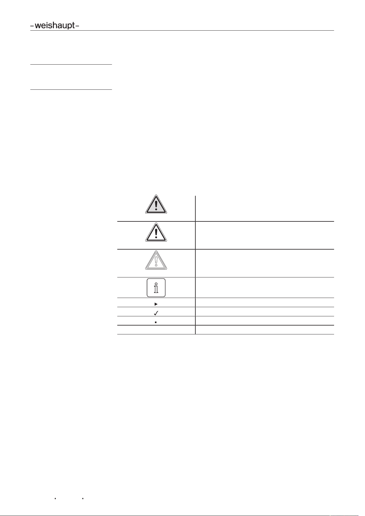
1.2 Symbols.......................................................................................................................... 3
1.3 Guarantee and Liability............................................................................................... 4
2 Safety ..................................................................................................................................... 5
2.1 Designated application............................................................................................... 5
2.2 Safety measures........................................................................................................... 5
2.2.1 Electrical connection............................................................................................5
2.2.2 Disposal...................................................................................................................5
3 Product description ........................................................................................................ 6
3.1 Inputs and outputs....................................................................................................... 6
3.1.1 Input .........................................................................................................................6
3.1.1.1 Gas burner / dual fuel burner gas operation............................................6
3.1.1.2 Oil burner / dual fuel burner oil operation.................................................6
3.1.2 Output......................................................................................................................7
3.1.2.1 Gas burner / dual fuel burner gas operation............................................7
3.1.2.2 Oil burner / dual fuel burner oil operation.................................................7
3.2 Technical data............................................................................................................... 8
3.2.1 Electrical data ........................................................................................................8
4 Installation ........................................................................................................................... 9
4.1 Installing analogue module ........................................................................................ 9
4.2 Setting the DIP switches..........................................................................................10
5 Installation ........................................................................................................................ 11
5.1 Electrical connection.................................................................................................11
6 Spares................................................................................................................................. 12
7 Key word index .............................................................................................................. 14

Installation and operating instruction
Analogue module EM3/3
1 User instructions
83295402 1/2019-01 La 3-16
1 User instructions
Translation of original
operating instructions
This manual forms part of the equipment and must be kept on site.
Carefully read the manual prior to working on the unit.
1.1 Target group
The manual is intended for the operator and qualified personnel. They should be
observed by all personnel working with the unit.
Work on the unit must only be carried out by personnel who have the relevant train-
ing and instruction.
Persons with limited physical, sensory or mental capabilities may only work on the
unit if they are supervised or have been trained by an authorised person.
Children must not play with the unit.
1.2 Symbols
DANGER
Immediate danger with high risk.
Non observance can lead to serious injury or death.
WARNING
Danger with medium risk.
Non observance can lead to environmental damage,
serious injury or death.
CAUTION
Danger with low risk.
Non observance can cause damage to the equip-
ment and injury to personnel.
Important information
Requires direct action
Result after an action
Itemisation
… Range of values

Installation and operating instruction
Analogue module EM3/3
1 User instructions
83295402 1/2019-01 La 4-16
1.3 Guarantee and Liability
Guarantee and liability claims for personal and equipment damage are excluded, if
they can be attributed to one or more of the following causes:
non approved application,
non-observance of the manual,
operation with faulty safety equipment,
continual operation despite a fault,
improper installation, commissioning, operation and service,
repairs, which have been carried out incorrectly,
the use of non original Weishaupt parts,
force majeure,
the installation of additional components, which have not been tested with the
unit.

Installation and operating instruction
Analogue module EM3/3
2 Safety
83295402 1/2019-01 La 5-16
2 Safety
2.1 Designated application
The analogue moduleEM3/3 is suitable for use with the combustion
managerW-FM 25.
2.2 Safety measures
Safety relevant fault conditions must be eliminated immediately.
2.2.1 Electrical connection
For work carried out on live components:
Observe the accident prevention instructions DGUVRegulation3 and adhere to
local directives,
tools in accordance with EN 60900 should be used.
2.2.2 Disposal
Dispose of all materials and components in a safe and environmentally friendly way
at an authorised location. Observe local regulations.

Installation and operating instruction
Analogue module EM3/3
3 Product description
83295402 1/2019-01 La 6-16
3 Product description
3.1 Inputs and outputs
The degree of modulation can be controlled via a control signal, which is connec-
ted to the input of the analogue module EM3/3.
The current degree of modulation can be signalled via an output from the analogue
module EM3/3.
3.1.1 Input
The analogue module EM3/3 has an analogue input.
The input can be set for the following ranges using a DIP switch:
current input 0…20mA or 4…20mA, depending on the range set,
voltage input 0…10V or 2…10V, depending on the range set.
3.1.1.1 Gas burner / dual fuel burner gas operation
Degree of modula-
tion
0…20mA 4…20mA 0…10V 2…10V
0% 0mA 4mA 0V 2V
10% 2mA 5.6mA 1V 2.8V
20% 4mA 7.2mA 2V 3.6V
50% 10mA 12mA 5V 6V
100% 20mA 20mA 10V 10V
3.1.1.2 Oil burner / dual fuel burner oil operation
Degree of modula-
tion
0…20mA 4…20mA 0…10V 2…10V
Stage1 <5mA <7.8mA <2.5V <4V
Stage2 >15mA >16mA >7.5V >8V

Installation and operating instruction
Analogue module EM3/3
3 Product description
83295402 1/2019-01 La 7-16
3.1.2 Output
The analogue module EM3/3 has two analogue outputs.
The outputs can be set for the following ranges using DIP switches:
current output 0…20mA or 4…20mA, depending on the range set,
voltage output 0…10V or 2…10V, depending on the range set.
3.1.2.1 Gas burner / dual fuel burner gas operation
Degree of modula-
tion
0…20mA 4…20mA 0…10V 2…10V
0% 0mA 4mA 0V 2V
10% 2mA 5.6mA 1V 2.8V
20% 4mA 7.2mA 2V 3.6V
50% 10mA 12mA 5V 6V
100% 20mA 20mA 10V 10V
3.1.2.2 Oil burner / dual fuel burner oil operation
Output1
The values outside of control mode and stage1 are identical.
Degree of modula-
tion
0…20mA 4…20mA 0…10V 2…10V
Outside of control
mode
0mA 4mA 0V 2V
Stage1 0mA 4mA 0V 2V
Stage2 20mA 20mA 10V 10V
Switch off point St2
running closed
14mA 15.2mA 7V 7.6V
Switch on point St2
running open
16mA 16.8mA 8V 8.4V
Output2
The values outside of control mode and stage1 are different.
Degree of modula-
tion
0…20mA 4…20mA 0…10V 2…10V
Outside of control
mode
0mA 4mA 0V 2V
Stage1 10mA 12mA 5V 6V
Stage2 20mA 20mA 10V 10V
Switch off point St2
running closed
14mA 15.2mA 7V 7.6V
Switch on point St2
running open
16mA 16.8mA 8V 8.4V

Installation and operating instruction
Analogue module EM3/3
3 Product description
83295402 1/2019-01 La 8-16
3.2 Technical data
3.2.1 Electrical data
Input
Voltage input 0/2V…10V
Input impedance 200kΩ
Current input 0/4mA…20mA
Input impedance 500Ω
Output
Voltage output 0/2V…10V
Internal resistance of source 83Ω
External impedance min 12 kΩ
Current output 0/4mA…20mA
Internal resistance of source 100Ω
External impedance 0.5 …2.2kΩ

Installation and operating instruction
Analogue module EM3/3
4 Installation
83295402 1/2019-01 La 9-16
4 Installation
4.1 Installing analogue module
DANGER
Risk of electric shock
Working on the device when voltage is applied can lead to electric shock.
Isolate the device from the power supply prior to starting any work.
Safeguard against accidental restart.
Unplug 7 pole connection plug on burner.
Remove cover1.
Carefully install module2 using the guides3.
Break out the pre-cut surfaces4 and fit cover1.
4
3
12
5
You can check if the combustion manager has recognised the module by interrog-
ating Information 13 in the Info level, see installation and operating manual of the
burner.

Installation and operating instruction
Analogue module EM3/3
4 Installation
83295402 1/2019-01 La 10-16
4.2 Setting the DIP switches
Check and adapt the setting of the DIP switches on the module.
1 2 3 4 5
O
N
DIP switches Explanation Setting
OFF ON
1Setting range(1 0…10V / 4…20mA 2…10V / 0…20mA
2Input function not activated activated
3Input setting Voltage Current
4Setting output 1 Voltage Current
5Setting output 2 Voltage Current
(1 The range set applies to the input and both outputs.
If different setting ranges are required for input, output 1 and / or output 2:
Activate parameter level, see burner installation and operating manual.
Select parameter 3 and set the value.
The setting can also be changed via the VisionBox Software on the PC using para-
meter 200.
Value(1 Setting range
Output 2 Output 1 Input
1(2 0…10V / 4…20mA 0…10V / 4…20mA 0…10V / 4…20mA
2Setting DIP switch 1 activated (factory setting).
3(2 0…10V / 4…20mA 0…10V / 4…20mA 2…10V / 0…20mA
5(2 0…10V / 4…20mA 2…10V / 0…20mA 0…10V / 4…20mA
7(2 0…10V / 4…20mA 2…10V / 0…20mA 2…10V / 0…20mA
9(2 2…10V / 0…20mA 0…10V / 4…20mA 0…10V / 4…20mA
11(2 2…10V / 0…20mA 0…10V / 4…20mA 2…10V / 0…20mA
13(2 2…10V / 0…20mA 2…10V / 0…20mA 0…10V / 4…20mA
15(2 2…10V / 0…20mA 2…10V / 0…20mA 0…10V / 4…20mA
(1 Only set the default values.
(2 Setting deactivates DIP switch1. The settings of DIP switches 2…5 remain effective.

Installation and operating instruction
Analogue module EM3/3
5 Installation
83295402 1/2019-01 La 11-16
5 Installation
5.1 Electrical connection
DANGER
Risk of electric shock
Working on the device when voltage is applied can lead to electric shock.
Isolate the device from the power supply prior to starting any work.
Safeguard against accidental restart.
The electrical connection must only be carried out by qualified electricians. Ob-
serve local regulations.
Connect inputs and outputs to connection diagram.
Out 2
GND
GND
Out 1
1
2
3
4
In
GND
+24 V
1
2
3
EM3/3
0/2 ... 10V 0/4 ... 20 mA
GND
GND
GND
0/2 ... 10V 0/4 ... 20 mA
24 V Ausgang
W-FM 25
1 2 3
1Output 2
2Output 1
3Input

Installation and operating instruction
Analogue module EM3/3
6 Spares
83295402 1/2019-01 La 12-16
6 Spares
1.01
1.04
1.03
1.02

Installation and operating instruction
Analogue module EM3/3
6 Spares
83295402 1/2019-01 La 13-16
Pos. Description Order No.
1.01 Analogue module set EM 3/3 for W-FM 25 230 110 12 422
1.02 Analogue module EM 3/3 for W-FM 25 660 350
1.03 4 pole plug 716 788
1.04 3 pole plug 716 787

Installation and operating instruction
Analogue module EM3/3
7 Key word index
83295402 1/2019-01 La 14-16
7 Key word index
C
Connection diagram...........................................................11
Current input.......................................................................... 8
Current output ....................................................................... 8
D
DIP switches ........................................................................10
Disposal .................................................................................. 5
E
Electrical connection..........................................................11
G
Guarantee............................................................................... 4
I
Input ......................................................................................... 6
Input impedance.................................................................... 8
Installation............................................................................... 9
L
Liability..................................................................................... 4
O
Output ..................................................................................... 7
P
Parameter level....................................................................10
S
Safety measures.................................................................... 5
Spares ...................................................................................13
V
Voltage input.......................................................................... 8
Voltage output ....................................................................... 8
W
Wiring diagram....................................................................11

83295402 1/2019-01 La

83295402 1/2019-01 La
WK Burners up to 32,000 kW
These industrial burners of modular
construction are adaptable, robust and
powerful.
Even on the toughest industrial applications
these oil, gas and dual fuel burners operate
reliably.
WKmono 80 Burners up to 17,000 kW
The WKmono 80 burners are the most
powerful monoblock burners from Weishaupt.
They are available as oil, gas or dual fuel
burners and are designed for tough industrial
application.
The complete program:
Reliable technology and prompt, professional service
W Burners up to 570 kW
The compact burners, proven millions of times
over, are economical and reliable. Available as
gas, oil and dual fuel burners for domestic and
commercial applications.
The purflam®burner version with special
mixing head gives almost soot-free combustion
of oil with greatly reduced NOx emissions.
monarch
®
WM Burners
and Industrial Burners up to 11,700 kW
These legendary industrial burners are durable
and versatile.
Numerous variations of oil, gas and dual fuel
burners meet a wide range of applications and
capacity requirements.
MCR Technology / Building Automation
from Neuberger
From control panels to complete building man-
agement systems - at Weishaupt you can find
the entire spectrum of modern control
technology. Future orientated, economical and
flexible.
Service
Weishaupt customers can be assured that
specialist knowledge and tools are available
whenever they are needed. Our service
engineers are fully qualified and have
extensive product knowledge, be it for burners,
heat pumps, condensing boilers or solar
collectors.
Max Weishaupt GmbH · 88475 Schwendi
Weishaupt close by? Addresses, telephone numbers etc. can be found
at www.weishaupt.de
We reserve the right to make changes. All rights reserved.
Water heaters/Energy storage
The diverse program of potable water and
energy storage for various heat sources
includes storage volumes of 70 to 3,000 litres.
In order to minimize storage losses, potable
water cylinders from 140 to 500 litres are
available with highly efficient insulation using
vacuum insulation panels.
Solar systems
The stylish flat-plate collectors are the ideal
complement for any Weishaupt heating
system. They are suitable for solar water
heating and for combined heating support.
With versions for on-roof, in-roof and flat roof
installations, solar energy can be utilised on
almost any roof.
Wall-hung condensing boilers
for gas up to 240 kW
The wall-hung condensing boilers WTC-GW
have been developed to meet the highest
demands in ease of operation and efficiency.
Modulating operation means these units
operate quietly and economically.
Floor-standing condensing boilers
for oil and gas up to 1,200 kW
The floor-standing condensing boilers
WTC-GB (up to 300 kW) and WTC-OB
(up to 45 kW) are efficient, low in pollutants
and versatile in use.
Even the largest capacities can be covered by
cascading up to four gas condensing boilers.
Heat pumps up to 180 kW
The heat pump range offers solutions for the
utilisation of heat from the air, the soil or
ground water.
Some systems are also suitable for cooling
buildings.
Geothermal probe drilling
With its daughter company, BauGrund Süd,
Weishaupt also offers geothermal probe and
well drilling. With the experience of more than
10,000 systems and more than 2 million meters
of drilling, BauGrund Süd offers a
comprehensive service program.
Table of contents
Other Weishaupt Control Unit manuals
Popular Control Unit manuals by other brands

Lanner
Lanner PGN-750 user manual

GORMAN-RUPP
GORMAN-RUPP GRP33-08A Installation, operation, and maintenance manual with parts list

Siemens
Siemens VALVEGYR LDU11.323A17 user manual

BHI
BHI ANEM Installation and operating manual

NXP Semiconductors
NXP Semiconductors TWR-K64F120M user guide

Siemens
Siemens SIMATIC ET 200SP IM 155-6 PN/2 HF manual

Nibe
Nibe OPT 10 Installer manual

Siemens
Siemens SITRANS FM MAG 8000 IIoT operating instructions

Mutable Instruments
Mutable Instruments Kinks Installation

Novar
Novar Trend 2VID installation instructions

DMG
DMG CITCAB user manual

National Instruments
National Instruments Phase Matrix PXI-1430B quick start guide