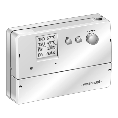
Weishaupt WRS User manual

End user
Weishaupt Controller System WRS 83051902 - 1/2003
Operating instructions
manual

2

General instructions 5
Safety instructions 6
About the Weishaupt Controller System 7
3.1 System execution 7
Operating and display elements of the direct setting level 8
How do I operate my heating system 9
5.1 Tips for comfortable ambience and economical heating 9
5.2 Changing room temperature/direct setpoint adjustment 9
5.3 Temporarily interrupting or extending the
heating program 9
5.4 Requesting information - Info mode 10
5.5 Selecting type of operation 11
5.6 Manual operation/Chimney sweep 12
Additional setting possibilities 13
6.1 Operating and display elements of the extended
setting level (flap open) 13
6.2 Where do I find ... ? 14
6.3 Removing the operating unit from its holder –
read/write data 15
6.4 Correcting time and change start/end of summer time 16
6.5 Call up and change heating program 17
6.6 Call up and change hot water program 18
6.7 Call up and change timer program
(only possible on the WRS-CPU-B2/E) 19
6.8 Call up and change temperature setpoints 20
6.9 Call up and change heating reference line
(weather compensated) 21
6.10 Energy saving function 22
6.11 Set holiday start/end 23
6.12 Type of operation 24
6.12.1 Set type of operation/call up error messages/
call up burner run time 24
6.13 Reset “Service” or “Flue Gas Limit” message
to factory settings 25
Operation with several address settings 26
7.1 Unit selection on multiple heating circuits 26
7.2 Special feature: Address 0 26
7.3 Central operating unit (control point) address 0, 2 26
7.4 Special feature: Address 2 27
What to do if ... ? 28
8.1 Error and service messages on the display 28, 29
8.2 Additional displays 30
8.3 Dwelling to cold or too warm 31
8.4 Deactivate heating circuit 31
8.5 Pump run on time 31
8.6 Sensor recognition 31
3
Contents 1
2
3
4
5
6
7
8

Parameter settings for your system 32
9.1 Parameter setting following commissioning 32
9.2 Equipment and configuration 34
9.3 Hand-over to the customer 34
Notes 35
4
9
A

5
1
•Your are holding the installation and operating manual
for the Weishaupt Controller System. Please study it
carefully.
•Please keep this manual with the system (use yellow
folder provided).
These installation and operating instructions
•are intended for the end user
•contain important information
•should be observed by everyone working with the
equipment.
Explanation of notes and symbols
This symbol is used to mark instructions,
which, if not followed, could result in death or
serious injury.
This symbol is used to mark instructions,
which, if not followed, could result in life
threatening electric shock.
This symbol is used to mark instructions,
which, if not followed, could result in damage
to, or the destruction of the equipment and
environmental damage.
☞This symbol is used to mark procedures,
which you should follow.
1. Procedures with more than one step are
2. numbered.
3.
❑This symbol is used when you are required to
carry out a test.
•This symbol is used to list points.
Abbreviations
Tab. Table
Ch. Chapter
Other abbreviations used:
WRS-CPU:Central electronics of boiler
WRS-BE: Operating unit
WRS-EM: Mixer extension module
WTU: Weishaupt Thermo Unit
HEL: Heating engineer level
EU: End user level
Hand over and operating instructions
The contractor is responsible for passing the operating
instructions to the plant operator prior to hand-over. He
should also inform the plant operator that these
instructions should be kept with the heating appliance. The
address and telephone number of the nearest service
centre should be entered on the reverse of the operating
instructions. The plant operator must note that an agent of
the contractor or other suitably qualified person must
inspect the plant at least once a year. To ensure regular
inspections, -weishaupt- recommends a service contract.
The contractor should instruct the plant operator in the use
of the equipment prior to hand-over and inform him as and
when necessary of any further inspections that are
required before the plant can be used.
Guarantee and liability
Weishaupt will not accept liability or meet any guarantee
claims for personal injury or damage to property arising as
a result of one or more of the causes below:
•Failure to use the equipment as intended.
•Improper assembly, commissioning, operating or
servicing of the equipment.
•Operating the appliance with defective safety
equipment, or with non-recommended or non-
functioning safety and protection devices.
•Failure to follow the information in the Installation and
Operating Instructions.
•Alterations made to the construction of the equipment
by the plant operator.
•Fitting additional components not tested or approved
for use with the equipment.
•Alterations made to the equipment by the plant
operator.
•Inadequate monitoring of parts liable to wear and tear.
•Improperly executed repairs.
•Acts of God.
•Damage caused by continued use despite the
occurrence of a error.
•Use of incorrect fuel.
•Obstruction or damage of the supply lines.
•Use of non-original -weishaupt- spare parts.
DANGER
ATTENTION
DANGER
1. General instructions

6
2Safety instructions
For your safety
☞Please observe the instructions given in this manual.
☞Please also observe the instructions given in the
operating instructions of the heat exchanger.
☞Please ask your heating engineer to instruct you in the
use of the system.
Dangers when using the equipment
Weishaupt products are manufactured in accordance with
the relevant existing standards and guidelines and the
recognised safety laws. However, improper use of the
equipment could endanger life of the user or a third party,
or result in damage to the plant.
To avoid unnecessary danger, the equipment is only to be
used:
•for its intended purpose
•under ideal safety conditions
•with reference to all the information in the installation
and operating instructions
•in accordance with inspection and service work
Errors, which could affect the safe operation of the
equipment, should be rectified immediately.
Personnel training
Only competent personnel may work on the appliance.
Competent personnel according to this operating manual
are persons who are familiar with the installation,
mounting, setting and commissioning of the product and
have the necessary qualifications such as:-
•Training, instruction, certification and authorisation to
switch electrical circuits and electrical devices on and
off, to earth them and to mark them in accordance with
the safety standards.
Organisational measures
•Everyone working on the plant should wear the
necessary protective clothing.
•All safety devices should be checked regularly.
Informal safety measures
•In addition to the installation and operating instructions,
local codes of practice should also be adhered to.
Special attention should be paid to the relevant
installation and safety guidelines given.
•All safety and danger notices should be kept in a
legible condition.
Safety measures in normal operation
•Only use the equipment when all the safety devices are
fully functional.
•At least once a year the equipment, including the safety
devices, should be checked for signs of visible damage
and to ensure that the safety devices are operating
correctly.
•More frequent safety checks may be required
depending on plant conditions.
Electrical safety
•Work on the electrical supply should be carried out by
a qualified electrician.
•Electrical components should be checked during
servicing. Loose connections and damaged cables
should be dealt with immediately.
•Should it be necessary to carry out work on life parts,
a second person should be present to switch off the
mains supply in an emergency.
Maintenance and error rectification
•Necessary installation, service and inspection work
should be carried out at the specified time.
•Inform the operator before beginning any service work.
•For all service, inspection and repair work, electrically
isolate the equipment and ensure the mains switch
cannot be accidentally switched back on. Isolate the
fuel supply.
•If, during servicing or testing, control seal joints have to
be opened, these have to be thoroughly cleaned to
ensure tight sealing when re-assembling.
Damaged seals must be replaced. Carry out a
soundness test
•Flame monitoring devices, limit controls, correcting
elements and all other safety devices must be
commissioned by, and may only be replaced by, the
manufacturer or an authorised agent.
•Screwed connections, which have been loosened,
must be re-tightened without cross-threading.
•Following service work, all safety devices should be
tested to ensure they are functioning correctly.
Alterations to the construction of the equipment
•No alterations to the equipment are to be made without
the approval of the manufacturer.
All conversions require written confirmation from
Max Weishaupt GmbH.
•Any parts not in perfect working order should be
replaced immediately.
•No additional components may be fitted, which have
not been tested for use with the equipment.
•Use only -weishaupt- spares and accessories as
replacement parts. Parts from other manufacturers are
not guaranteed to be suitable to meet the necessary
operational and safety requirements.
Cleaning of the equipment and waste disposal
•All materials used should be handled and disposed of
correctly, with due regard to the environment.

In its basic execution, the Weishaupt controller system
WRS consists of
Package Thermo Unit WTU
Boiler body incl. cladding
Package Boiler control
Boiler operating panel (WRS-KF):
Is used to set Manual/Automatic operation
(see boiler operating instructions)
Base module (WRS-CPU):
Includes boiler controller and the control
of one heating circuit.
Operating unit (WRS-BE):
The setting of the control is carried out
with the Operating Unit. The operating
unit can be removed from its holder.
That means settings can be made from the
armchair. When the operating unit has
been removed from its holder, it no longer
records the temperature in the room.
However, this does not restrict the
operation of the heating system.
You have access to two operating levels:
Direct setting level for easy operation of basic
functions such as warmer/colder, type of operation,
calling up information, interrupting or extending the
heating program.
Extended setting level to set additional heating
functions, such as warm water temperature,
heating reference line, changing heating program,
holiday function, etc.
Your heating engineer has access to further settings
to ensure your heating system can be optimised to meet
your requirements.
The Weishaupt controller system can be extended with:
Extension module (WRS-EM)
8 additional modules for the control of
heating circuits and their associated
operating units.
7
3. About the Weishaupt Controller System 3
The Weishaupt Controller System WRS provides
easy and energy saving control of your heating system.
Some characteristics of the Weishaupt Controller
System:
Easy selection of the type of operation
with a selection switch.
Easy interruption or extension
of the heating program by pressing
a push button.
Easy interrogation of Information about
your heating system and current
temperatures.
Three heating programs, one warm wa-
ter program and one freely programmable
time program for specific operation of the
heating system. Easy setting of switch times.
Temperature set point default for normal
temperature, warm water temperature,
economy temperature, frost protection
temperature, summer/winter changeover
temperature.
Holiday function for reduced heating
during absence.
Easy alignment of heating control
to ambient conditions.
Easy Reset to factory settings.
prog
Reset
3.1 System execution

8
4Operating and display elements of the direct setting level
Time indicator
Shows the time of day, during
which the heating is operated in
normal mode
or
economy mode.
Selection switch for type of
operation
to select types of operation:
Summer operation
Operation in economy
mode
Operation in normal
mode
prog 1 Heat program 1
2Heat program 2
3Heat program 3
Standby operation
Info key
• Each time it is pressed a current
actual value is displayed
• Reset to basic display
Attendance/absence key
Temporarily interrupts or extends
the heating program
Enter key
Selections or changes are
confirmed by pressing this key
Dial knob
By turning the current temperature
setpoint can be displayed
#Error condition or
service required
Heating currently operating
in economy mode
Heating currently operating
in normal mode
Symbols on the display
When operating the direct setting level please note:
❑The operating unit must be fitted to the boiler cover or the wall bracket.
❑The boiler controller on the boiler control panel must be set to “auto”.
(The cover of the boiler control panel can only be closed in this position)
Operating unit in boiler cover – boiler controller to “auto” Operating unit in wall bracket
· auto
80°C
55°C
30°C
Display
which address (unit) the operating
unit is assigned to
#

9
5 How do I operate my heating system 5
5.2 Change room temperature / direct setpoint adjustment
Why?
If your living quarters are too warm or too cold,
you can adjust the normal temperature, the
economy temperature or the frost protection
temperature using the turn knob.
You can also adjust the set temperatures of the other
types of operation.
To do this, place the selection switch to the type of
operation to be changed.
Normal temp
50 21°C
Economy temp
51 C
Normal temp
50 21°C
Confirm alteration and
return to base display
Cancel?
Alter
temperature
Press
Turn until
display
is shown Frost prot temp
52 10°C
Display as per
current type of
operation
Thursday 12:41
1
Thursday 15:41
1
5.3 Temporarily interrupting or extended the heating programme
Why?
You have set one of your heating programmes.
The heating system is operating according to
the heating circuit either on normal
temperature or economy temperature.
However, your heating system does not match
your requirements for that particular day.
You can now temporarily interrupt or extend
the heating programme. An interruption will last until the
next switchover in the heating programme, or until you
return to the normal heating programme by pressing the
button.
Heating to economy temperature when not present
Heating to normal temperature when present
Temporarily change from
economy temperature to
normal temperature
Temporarily change from
normal temperature to
economy temperature
info
Note:
The setpoint adjustment affects only that unit who’s
address is shown on the display.
Reducing the room temperature by just 1°C can save
up to 6% fuel. Therefore avoid excessive room
temperatures and set your heating system accordingly.
Make use of the multitude of types of operation and
heating programs to ensure the heating system
operates only when actually needed.
Air rooms for short periods only, but several times a
day.
Seal doors and windows to stop draughts.
Close window and door shutters at night.
Ensure that heating and hot water pipes are insulated.
Avoid enclosed radiators. Do not cover radiators.
Energy can also be saved by careful use of hot water.
A shower uses less energy than a bath.
Turn your tap fully to “cold”, if you do not require warm
water. If it is not fully on cold, warm water is always
being added.
Operate circulation pump for warm water via time
switch program only during operation.
Do not forget servicing!
Your heating system should be checked at least once a
year by a qualified heating engineer.
Regular servicing saves fuel and ensures
continually good combustion quality.
5.1 Tips for convenient control and economical heating

Type of operation
as per setting of selection switch or
setting in the extended setting level
Type of operation
as per setting of selection switch or
display of the type of operation activated in
the extended setting level
- or -
• if switch on
boiler operating panel not on “auto”
• if heating circuit deactivated (gradient - - -)
• if floor drying function activated
(Activation in HE, parameter 180 ➩“Sync. heating”)
• if holiday function activated
(M1 contact activated during switch-over to Standby)
• if heating off, hot water On
• if heating pump Off,
boiler in frost protection operation
Manual 15:41
15:41
............
10
5
5.4 Call up information – Info mode
Why?
With every push of the Info button current
values of the heating system are displayed
one after the other.
The value remains as a continuous display relative to the
selected information.
1.) Only shown on specific system versions
2.) Not shown on address 0, A, B, C
3.) Shown only on address 0, 1 and 2*
Note: It can take up to 10 mins. before the hot water sensor
value is displayed.
4.) Shown only on address 1
5.) Shown only on address 0, 1, A, B, C
Screed 15:41
............
Holiday 15:41
............
Summer 15:41
............
Economy 15:41
............
Time
Current room temperature ➩2.)
Current external temperature
Current boiler temperature ➩4.)
Current supply temperature
of heating circuits 1 ... 8
Unit errors if present, service notification
if boiler service required (see Ch. “What to do
when ... ?”).
info
Current warm water temperature ➩3.)
Boiler 52°C
1
Program1 15:41
1
Current calorifier temperature top ➩1.)
Current burner relay display ➩5.)
Current calorifier temperature bottom ➩1.)
Program 1 15:41
1

11
5
5.5 Select type of operation
Continuous summer operation
Heating is off, hot water is
available.
Continuous heating
Heating maintains the room
temperature set independent
of external temperature, hot
water is available.
Continuous economy
operation
The heating system maintains
economy operation depending
on the external temperature. If
Economy or Summer/Winter
switchover is active, the heating
circuit and boiler are reduce to
the frost protection level. Hot
water is available.
Continuous frost protection
temperature
Boiler at frost protection level,
heating operation only when
frost protection temperature not
achieved. No hot water.
Heating program 1
Heating and economy operation
as programmed, hot water is
available.
Heating program 2
Heating and economy operation
see heating program 1
Heating program 3
Heating and economy operation
see heating program 1
➩Read Ch. 6.5 when changing
the heating programs.
prog
prog
1
2
prog
3
Summer 15:41
1 ............
Why?
You can select 7 different types of operation
with the selection switch for type of operation.
(On operating unit address “0..” HE,
parameter 910 ➩“0” not possible).
Please note
The display pictures shown only appear, when the
information about the type of operation is called up by
pressing the Info button. Otherwise the information last
called up with the Info key remains displayed.
prog
Standard heating program 1
Mon to Fri 06:00h to 22:00h Normal temp
Sat and Sun 07:00h to 23:00h Normal temp
Standard heating program 2
Mon to Fri 05:30h to 08:30h Normal temp
12:00h to 22:00h Normal temp
Sat and Sun 07:00h to 23:00h Normal temp
Standard heating program 3
Mon to Fri 07:00h to 22:00h Normal temp
Sat and Sun 07:00h to 24:00h Normal temp
Make use of the factory preset heating programs:
Economy temperature
at all other times
➩If Summer is set using
the selection switch
for type of operation, it
is possible that the
display changes to
“Economy”. This
depends on the
Summer/Winter
switchover
temperature.
However, the function
continuous summer
operation is carried
out in any case.
Note:
DHW supply
is not affected, except
in Standby, where
DHW loading is
not carried out.
Normal temp 15:41
1
Economytemp 15:41
1
Program1 15:41
1
Program2 15:41
1
Program3 15:41
1
Standby 15:41
1

12
5
5.6 Manual operation / chimney sweep
Why?
Using the selection switch on the boiler
control panel Automatic or Manual
operation can be selected. Turn the
selection switch to manual for the emission
test (chimney sweep), for emergency
operation or for commissioning.
Please note
The display shows Manual instead of Program 1.
Selection switch on boiler
control panel not in “auto”
All 230 Volt outputs are activated, this
activates all pumps.
The temperature limits, which are given
electronically by the controller, are ignored.
The hot water temperature can become the
same as the boiler temperature. This
depends on the position of the selection
switch on the boiler control panel.
If the hot water temperature is ≥60°C, it is
possible to get scalded, as any circulation
pump fitted can also pump the hot water
directly to the tap.
Note: If the selection switch is taken out of “auto”
mode, it should be set to a position where the
selected temperature cannot be life
threatening (≤60° C).
The selection switch should normally be set to Automatic.
ATTENTION
Manual 15:41
1

13
6 Additional setting possibilities 6
1:Operator -/+
Setting values
Return to the direct
setting level or Info level.
This button is used to abort the
settings. Any unsaved changes
will be lost.
Extended setting level
To select the extended setting level.
– or –
A step back
(unsaved alterations are lost).
The dial knob has two functions:
1. Selection of parameter groups or
parameters.
2. Alteration of setting values.
Only for the heating engineer.
This button confirms the selection
you made with the dial knob or the
alterations made to the setting
values.
6.1 Operating and display elements of the extended setting level (flap open)
Gradient
54 $$$
Gradient
54 ---
S/W switchover
53 20.0
Function not active, heating circuit
switched off.
Function is activated once a value
has been set.
“ -/+” shows that other parameter
groups can be selected by turning
the dial knob.
A flashing parameter value can be
altered with the dial knob.
“Operator” shows that you are in
the extended setting level.
“1:” marks the selected heating
circuit (here heating circuit 1)
Parameter number
Value not yet available,
searching.
The control of your heating system has been factory
preset. These standard settings (see Ch. 9.1) were
selected in such a way that you will need to make very
few changes.
However, if you want to make changes anyway, these
can be made in the extended setting level.
You can also carry out these settings when the
operating unit has been removed. Please observe the
notes in Ch. 6.3.
Meaning of display

14
6
1:Operator -/+
Time
1:Operator -/+
Heat program 1
1:Operator -/+
Heat program 2
1:Operator -/+
Heat program 3
1:Operator -/+
DHW program
Basic display in the direct setting level
6.2 Where do I find…
1:Operator -/+
Setting values
1:Operator -/+
Holiday
1:Operator -/+
Type operation
1:Operator -/+
Options
901 Time
902 Summer time start
903 Summer time end
11 Heat cycle Mon.
- - -
17 Heat cycle Sun.
18 Heat cycle week.
31 Heat cycle Mon.
- - -
37 Heat cycle Sun.
38 Heat cycle week.
41 DHW-Cycle Mon.
- - -
47 DHW-Cycle Sun.
48 DHW-Cycle week.
50 Normal temp
51 Economy temp
52 Frost prot
53 S/W switchover
54 Gradient
55 DHW setpoint
60 Holiday from
61 Holiday to
62 Holiday temp
70 Program 1
71 Error message
72 Burner runtime1
73 Burner start 1
74 Burner runtime21)
75 Burner start 21)
80 Parameter Reset ?
81 Service
82 Max val flue gas
21 Heat cycle Mon.
- - -
27 Heat cycle Sun.
28 Heat cycle week.
1.) Only displayed on WRS-CPU-B2 2.) Only displayed on WRS-CPU-B2/E 3.) Only shown for address
and WRS-CPU-B2/E 0, 2* / HE: Parameter 910
➩
0.,2*
Only shown for
address 0, 1 and 2
(
➩
Ch. 6.4)
1:Operator -/+
Program 5
1 ProgCycle Mon.
- - -
7 ProgCycle Sun.
8 ProgCycle week.
Select
parameter
by durning
dial knob
(
➩
Ch. 6.5)
(
➩
Ch. 6.5)
(
➩
Ch. 6.6)
(
➩
Ch. 6.7)
(
➩
Ch. 6.8; 6.9;
6.10)
(
➩
Ch. 6.11)
(
➩
Ch. 6.12)
(
➩
Ch. 6.13)
2.)
info
Unit selection
1:WRS-CPU-B1 Make unit
selection
3.)

15
6
Read data?
Read data
Monday 13:45
No connection
Unit selection
1:WRS-CPU B2
Read data
920 Yes
Data is
transferred
6.3 Removing the operating unit from its holder – read/write data
Removing the operating unit from its holder
Replacing the operating unit into its holder
Remove operating unit
Now the settings can be altered.
Write data
930 Yes
Unit selection
1:WRS-CPU B2
Data is
transferred
Replace the operating unit into its holder.
If you have altered the settings the display
shows:
To be able to alter the settings with the operating unit
removed from its holder it needs the current boiler
data. This data must first be transferred from the boiler
to the operating unit.
If you have altered the settings with the operating unit
removed from its holder, this data has to be transferred
from the operating unit to the boiler.
Cancel unit
selection
info
info
Cancel unit
selection
info
If other units are available
Note: The Info level can only be called up
(Info button) or influenced (present/absent
button, selection switch for type of operation)
if the operating unit has contact with the Bus
system.
Program1 15:41
1
Program1 15:41
1

16
6
6.4 Correcting time and change start/end of summer time
Why?
To ensure the correct operation of the heating
system, the controller requires the exact time.
The time has been factory preset.
If the mandatory time for summer time start/end is different,
you can enter these changes here.
Time 09:03
901 27.Sept 2000
Time 09:03
901 27.Sept 2000
Time 09:03
901 27.July 2000
1:Operator -/+
Time
Summer Start
902 25. Mar
Summer Start
902 25. Mar
Summer End
903 25. Oct
Summer End
903 25. Oct
Summer End
903 25. Oct
Summer End
903 25. Oct
Summer Start
902 25. Mar
Summer Start
902 25. Mar
- or -
- or -
- or -
return?
return?
return
continue ?
Press
Turn until
display shows
same procedure for
• minute
• year
• month
• day
Note: You must check all setting parameters one by
one (hour, minute, year, month, day), as data is not
automatically backed up when exiting the level
by pressing the button or button.
info
Press to request the time Press to allow the setting
Press to confirm month
Press to confirm day
Press to allow the setting
Press to confirm the month
Press to confirm the day

17
6
6.5 Call up and change heating programs
Why ?
You can adjust the heating times to
meet your daily routine.
There are three independently operating
heating programs available for each
heating circuit.
Up to three heat cycles per week day can
be entered for each heating program.
A standard program has been factory pre-
set (see Ch. 9.1). You can reset this stan-
dard program with your heating programs
at any time (see Ch. 6.13).
Example for 2 heat cycles on one day
0h 6h 12h 18h
16,0°C
21,5°C
1. Start 1. End 2. Start 2. End
1. Heat cycle 2. Heat cycle
Normal temperature
Economy temperature
1:Operator -/+
Heat program1
1:Operator -/+
Heat program2
1:Operator -/+
Heat program3
Heat cycle Mon.
11
Heat cycle Mon.
11
Heat cycle Tues.
12 ............
Heat cycle Wed.
13 Heat cycle...
Heat cycle Week
18 ............
Mo:1.Start06:00
11
Mo:2.Start--:--
11
Mo:1.End 22:00
11
Mo:2.End --:--
11
Mo:3.Start--:--
11
Mo:3.Start--:--
11
- or - next week day?
return?
If no entry at “2.Start”
Press
Turn until
display
shows
Press to call up
heat program 1 select next heat programs
press to call up heating cir-
cuit Monday
If entry at “2.Start”
Note: The time program should be selected in such a
way that one heat cycle is programmed until
20.00 hrs. so that the heating pump remains
switched off during night setback without frost
protection until the next heat cycle.
In parameter 18 you can set a heat cycle
for the whole week. This takes
precedence over settings made for
individual week days.
Press to confirm setting
Press to confirm setting If entry at “3.Start”
21.5°C
16.0°C

18
6
6.6 Call up and change D H W program
Why?
You can adjust the heat-up times to
meet your daily routine.
A maximum of three cycles per week day
can be set in the hot water (DHW)
program.
A standard program has been factory pre-
set (see Ch. 9.1). You can reset this stan-
dard program with your DHW program at
any time (see Ch. 6.13)
Note: D H W loading is provided depending on the
settings made in parameter 160 of the heating
engineer level. It is therefore possible that
DHW loading is not provided in line with the
DHW program, but dependant on the the
heating program.
Example for 2 D H W cycles on one day
0h 6h 12h 18h
50°C
1. Start 1. End 2. Start 2. End
1. Cycle 2. Cycle
Normal temperature
Economy temperature
1:Operator -/+
DHW Program
DHW Cycle Mon.
41
DHW Cycle Mon.
41
DHW Cycle Tues.
42 ........
DHW Cycle Wed.
43 ............
DHW Cycle Week
48 ............
Mo:1.Start06:00
41
Mo:2.Start--:--
41
Mo:1.End 22:00
41
Mo:2.End --:--
41
Mo:3.Start--:--
41
Mo:3.Start--:--
41
- or - next week day?
return?
If no entry at “2.Start”
Press
Turn until
display
shows
press to D H W-program
Press to call up DHW Cycle
Monday
If entry at “2.Start”
In parameter 48 you can set a heat cycle
for the whole week. This takes
precedence over settings made for
individual week days.
Press to confirm entry
Press to confirm entry If entry at “3.Start”

19
6
6.7 Call up and change timer program (only possible on the WRS-CPU-B2/E)
Why?
Independent time program, freely
programmable timer, i.e. circulation
pump.
In program 5, up to three cycles can be
entered for each week day.
A standard program has been factory preset
(see Ch. 9.1). You can reset this standard
program with your program 5 at any time
(see Ch. 6.13)
Program 5 can be assigned to MFA relay
output (230 V, plug No. 3) and burner
stage 2 (potential free contact, plug No. 20)
of the CPU (see heating engineer level,
parameter 174 ➩“Prog 5”).
Example for 2 program cycles on one day
0h 6h 12h 18h
Ein
Aus
1. Start 1. End 2. Start 2. End
1. Cycle 2. Cycle
On
1:Operator -/+
Program 5
ProgCycle Mon.
1
ProgCycle Mon.
1
ProgCycle Tues.
2 ProgZ.....
ProgCycle Wed.
3 ............
ProgCycle Week
8
Mo:1.Start06:00
1
Mo:2.Start--:--
1
Mo:1.End 22:00
1
Mo:2.End --:--
1
Mo:3.Start--:--
1
Mo:3.Start--:--
1
- or - next week day?
return?
If no entry at “2.Start”
Press
Turn until
display
shows
Press to call up
circulation program
Press to call up circ. cycle
Monday
If entry at “2.Start”
In parameter 8 you can set a heat cycle
for the whole week. This takes
precedence over settings made for
individual week days.
Press to confirm entry
Press to confirm entry If entry at “3.Start”
On
Off

20
6
6.8 Call up and change temperature setpoints
Why?
Your heating control operates to different
temperature setpoints, stipulated by you.
Normal temperature setpoint:
Your selected room temperature.
Economy temperature setpoint:
Your selected room temperature outside of
operating times, for example during the
night.
Frost protection temperature setpoint:
Protects the building from frost damage.
Please note: Frost protection is only
ensured if the heating system functions
correctly.
Note: The frost protection temperature only has an
effect if the room factor is activated.
Summer/Winter switchover temperature:
Operation without intervention for a whole year is
possible.
The heating system does not start during short cold
snaps.
Summer/Winter switchover is not carried out
depending on the current external temperature, but
depending on an average external temperature
determined over time (External dampened). With this
the heating is switched off when the dampened
external temperature is 2° C above the switchover
temperature. If the dampened external temperature
is 1° C below the switchover temperature, the heating
circuit is re-activated. The dampened external
temperature can be called up in the heating engineer
level parameter ➩111.
DHW temperature setpoint:
You program the required hot water temperature into your
heating control.
Danger of scalding!
Excessively high hot water temperatures can
lead to scolding.
DANGER
1:Operator -/+
Setting values
Normal temp
50 21.5°C
Normal temp
50 20.0°C
Economy temp
51
Frost prot 52
S/W Switchover
53 20.0°C
DHW setpoint
55 50°C
Normal temp
50 21.5°C
- or -
next setting
value?
return?
Press
Turn until
display shows
Press to call up
setting values
Press to carry out setting
Press to confirm settings
Table of contents
Other Weishaupt Controllers manuals
Popular Controllers manuals by other brands

oventrop
oventrop Unibox RTL operating instructions

Furious FPV
Furious FPV Fortini F4 OSD REV.3 user manual

Servomech
Servomech ATL 02 Installation, operation and maintenance manual

BLEMO
BLEMO ER41 manual

PIETRO FIORENTINI
PIETRO FIORENTINI REVAL 182 Technical manual

Airwell
Airwell RCW22 Installation and owner's manual