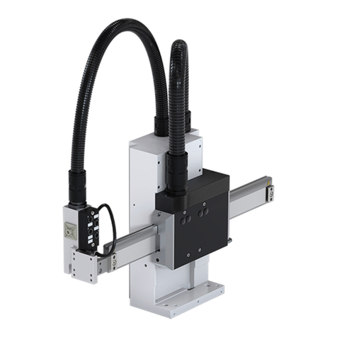
WEISS HP140 User manual

04
/2010

WAS.handling Electro Documentation
This documentation is copyright-protected. Duplication (even of extracts) is not permitted without the prior
written consent of WEISS GmbH.
WEISS GmbH reserves the right to make alterations to this documentation (also without prior notice).
WEISS GmbH is not liable for any technical or printing errors in this document. We accept no liability for
damages directly or indirectly related to the provision or use of this documentation.
This does not include damages arising from death, personal injury or damage to health or to such damages
resulting from a grossly negligent or deliberate infringement of obligations.
Windows and Windows XP are registered trade marks of Microsoft Corporation in the USA and/or other
countries.
Release: April 2010
Copyright WEISS GmbH Sondermaschinentechnik
Siemensstraße 17
D-74722 Buchen / Odw.
Tel.: +49 /(0)6281/5208-0
Internet: www.weiss-gmbh.de

WAS.handling Electro Documentation
Table of contents
1 Safety Instructions ........................................................................................................................................1
1.1 Description of Symbols .............................................................................................................................1
1.2 Safety Instructions.....................................................................................................................................2
2 Product description.......................................................................................................................................5
2.1 Overview ...................................................................................................................................................5
2.2 Technical Data ..........................................................................................................................................6
2.3 Terminology.............................................................................................................................................10
3 Installation....................................................................................................................................................11
3.1 Installation of ACOPOS drives................................................................................................................11
3.2 Electrical installation ACOPOS drive.......................................................................................................15
3.3 Installation of external I/O-Module ..........................................................................................................22
3.4 Electrical installation of I/O-Module........................................................................................................23
3.5 Connection Diagram for control cables...................................................................................................24
3.6 Motor connection.....................................................................................................................................25
3.7 Customers interface................................................................................................................................26
4 Getting started .............................................................................................................................................30
4.1 Drive controls ..........................................................................................................................................30
4.2 Slot-PLC..................................................................................................................................................33
4.3 Mechanics, Motors and Feedback..........................................................................................................34
4.4 Machine Zero Position.............................................................................................................................35
4.5 Windows User Interface - Software ........................................................................................................36
5 Service und Maintenance............................................................................................................................37
5.1 Battery Replacement...............................................................................................................................37
6 Appendix.......................................................................................................................................................39
6.1 Assignment of Cables.............................................................................................................................39

1 WAS.handling Electro Documentation
1 Safety Instructions
1.1 Description of Symbols
Warnings are emphasized by a safety symbol and are shown as follows depending on the degree of risk:
Danger !
Imminent danger. Fatal injury, death or substantial material damage can be
caused if the appropriate safety measures are not taken!
Warning!
Minor injuries may occur if the appropriate safety measures are not taken.
Electrical hazard
Warning against hazardous voltage.
Useful Information.

WAS.handling Electro Documentation 2
1.2 Safety Instructions
Validity:
These instructions apply for the WEISS control system HP140T with B&R servo drive ACOPOS 8V1010.50-2.
Importance of the operating instructions:
This manual contains important information for working safely with the control system. It contains safety
instructions which must be observed as well as information necessary for trouble-free operation.
The operating instructions must be kept with the device. It must be ensured that all persons who work at the
device have access to the operating instructions at all times.
In addition to the operating instructions for the control system, the operating instructions for the mechanics, as
well as the operating regulations subject to the labour protection laws must also be provided.
The operating instructions must be kept in a safe place for further use and must be passed on to every
subsequent owner, user and end customer.
The HP140 may only be started up when the whole machine and control system, in particularly the safety
system, correspond to the machinery directive 98/37/EC.
Target group:
The operating instructions are aimed at persons who are involved in the planning, installation, starting-up, and
maintenance of the system and who have the qualifications and know-how appropriate for this work. Qualified
personnel are persons who have the necessary qualifications and who are familiar with the execution of the
work cited above and the operation of the system. All work in other areas such as transport, storage and
disposal must be carried out by persons with the appropriate training.
General:
Prior to installation and starting up, please carefully read and observe all safety instructions, technical
documentation and connection data accordingly. National accident prevention regulations and all internal
company regulations must be observed.
Never install or operate damaged products.
The devices must be installed and cooled in accordance with these regulations.
The control system (PLC and servo drive) must be protected against overloading. The servo amplifier and PLC
contain electrostatically sensitive components that can easily be damaged by improper handling. Electrical
components may not be mechanically damaged or destroyed (possible health risk).
Danger!
In the case of unauthorized removal of the necessary cover, inappropriate usage,
incorrect installation or operation, there is a risk of serious personal injury or
material damage.
Warning!
Depending on the type, some of the components (motor, servo drive) may have
hot surfaces during operation. Operating temperatures > 60 °C (> 140 °F) can
occur. Skin contact will cause burns.

3 WAS.handling Electro Documentation
WEISS devices conform to the relevant VDE regulations. The VDE regulations must also be observed in the
case of modification or extension of the devices.
This documentation contains instructions for EMC installation - including screening, earthing and installation of
the lines. Compliance with the limit values stipulated by EMC legislation is the responsibility of the
manufacturer of the system or machine.
Unauthorized alterations and the use of spare parts and additional devices which are not recommended by the
manufacturer can cause personal injury or damage to the mechanism and the control system.
Before switching on the control system you must ensure that the housing is correctly earthed (PE rail).
The servo drive may only be operated directly on earthed, three-phase industrial networks (TN, TT network).
Control and power connections may have voltage even if the motor is standing
still. Never connect or disconnect the electrical connections of the device when
it is live.
Connection terminals may only be connected or disconnected when the power is off!
Do not touch live parts of the device or power connections (in particular the power line and the motor line)
immediately after disconnection of the servo drive from the supply voltage due to the possibility that capacitors
are still charged up.
After switching off the device, wait for at least 5 minutes and then check at the
terminals “+DC1“ and “-DC1“ whether the capacitor has discharged to voltages
< 42 VDC before touching live parts or disconnect connections.
The fact that the LED‘s on the ACOPOS drive are off, are no indication that the device is disconnected from
the power supply and voltage-free.
In the case of unauthorized removal of the necessary covers, inappropriate usage, incorrect installation or
operation, there is a risk of serious personal injury or material damage..
Residual-current-operated circuit breaker (RCD):
Servo drives have an internal power rectifier. In the event of an earth contact, a flat fault direct current can
prevent the triggering of an AC current or pulse current sensitive RCD and thus suspend the protective function
for all devices connected to this network.
An AC/DC sensitive, selective RCD (Type B) in accordance with DIN-VDE 0644-100 must be used.
Take note that even if the correct RCD is used, there can still be spurious tripping due to high leakage current.
We thus recommend a current rating > 100 mA.
Only install the residual-current-operated circuit breaker between the mains supply and the servo drive..

WAS.handling Electro Documentation 4
Emergency Stop:
Suitable protective devices in accordance with EN60204 Part 1 must be used.
Danger!
Adequate protective devices, e.g. covers, protective grids, light curtains or stop
sensor must be installed for operation in order to protect the operating
personnel from injury by the HP140.
The clamp “Enable” at the ACOPOS drive (terminal X1/9) is implemented as a so-called “secure restart inhibit”
to deactivate the system and prevent unexpected restart.
This allows maximum safety category:
Norm: EN 954-1: Category 3
Norm: EN ISO 13849: SL 2 / Pl d
Overview of individual safety functions that can be implemented:
Label according to standard:
EN 61800-5-2 EN 60204-1 Short description
STO (Safe Torque off) Stop Category 0 Shut-down by immediate switching-off of the energy supply to
the drive machinery (i.e. an uncontrolled shut-down).
SS1 (Safe Stop 1) Stop Category 1 Introduction of active braking and activation of the STO
function after a defined amount of time has expired.
(Implementation by user)
This is described in a separate chapter of these Operating Instructions (Section 4.1.2). This must be observed.
A wiring diagram is also provided in this document (Section 3.2.2).
Designated use:
This device is designed for industrial and commercial systems and conforms to the valid standards and
regulations. All of the instructions regarding technical data and the permissible conditions at the place of
installation must be observed. This device is a component for installation in machines. Start-up (start of
designated operation) is not permitted until it has been established that the machine is in conformance with the
EMC directive 89/336/EEC and the end product is in conformance with the machinery directive 89/37/EC.

5 WAS.handling Electro Documentation
2 Product description
2.1 Overview
The device consists of the following assemblies:
•mechanic
•drive controls
•cable set
•option: digital I/O
internal CAN-Bus
customer interface:
digital inputs
customer interface:
digital outputs
mains connection
motor line red
encoder line red
Eingänge des
Verstärkers:
- Enable (Not-Aus)
- Quickstop
- 24V Versorgung
customer interface
- Profibus or
- CAN
option:
1 or 2 digital -
I/O-Moduls
with 16 In- and
Outputs each
motor line blue
encoder line blue
drive control
Z-Axis
Parameterization via
RS232 or Ethernet
drive control
Y-Axis
Ethernet

WAS.handling Electro Documentation 6
2.2 Technical Data
2.2.1 Drive control – power section:
Depending on customer requirement, one of the following drive controls is used:
Model: ACOPOS 8V1010.50-2 ACOPOS 8V1022.50-2
Permitted temperature ranges: storage: -25°C...+55°C
operation: 0°C...+40°C
Installation position: vertical
Air humidity: 5 to 95%, without condensation
Mains input voltage: 3 x 110 VAC to 230 VAC ± 10 %
or
1 x 110 VAC to 230 VAC ± 10 %
Mains filter according to EN 61800-
3-A11 second environment (Limits
from CISPR11, Group 2, Class A)
3 x 400 VAC bis 480 VAC ± 10 %
Mains filter according to EN 61800-
3-A11 second environment (Limits
from CISPR11, Group 2, Class A)
Frequency mains supply: 48 – 62 Hz
Installed load: max. 1,35 kVA max. 3 kVA
main fuse: 10 A time delay
(both axes together) 10 A time delay
(both axes together)
Peak current: 7,8 Aeff 14 Aeff
Continuous current: 2,0 Aeff 2,2 Aeff
Starting current: 5 A (at 230 VAC) 4 A (at 400VAC)
Switch on interval: > 30 sec
Power loss: < 80 W < 120 W
EMC: according to EC directive 89/336/EWG
applicable harmonized standards:
EN 61800-3 (noise resistance)
EN 550011, class B (noise emission)
Low voltage directive: according to EC directive 73/23/EWG
applicable harmonized standards:
EN60204.1 / VDE113
Protection according to
IEC 60529:
IP 20
C-UL-US listed: yes
Dimensions: width: 58,5 mm
height: 257 mm
depth: 220 mm
width: 70,5 mm
height: 375 mm
depth: 235,5 mm
Weight: 2,5 kg 4,0 kg
2.2.2 Drive control – 24V-control section:
24 Volt control voltage: 24V DC +/-10%, residual ripple < 10%
Power consumption 24 Volt: max. 2.5A / 1.2A typical
- note: 24V for fan is provided from DC-Bus
- note: Fuse: 6A time delay
Input voltage 24V nominal / 30V max.
Switching threshold LOW <5V
HIGH >15V
Input current approx. 30mA at 24V
Enable Input – X1/9
Switching delay <2ms
number of inputs 2
level LOW <5V
HIGH >15V
input current approx. 4mA at 24V
Digital Inputs – CPU X4:
(4.1; 4.2)
input filter <1ms
number of outputs 1
Digital Outputs – CPU X4:
(4.3) output current max. 0.5A each Output
Profibus (optional) Profibus DP Slave, ≤12Mbit, potential separation
CAN-Bus (optional) 500kBit/s, potential separation

7 WAS.handling Electro Documentation
In one of the drive controls, there is a Slot –PLC of type AC140 or AC141 integrated. These modules have an
exchangeable program memory in the form of a compact flash card as well as a separate backup battery.
The AC140 is equipped with Profibus and the AC141 with CAN-bus
This Slot-PLC represents the hard- and software interface to customers PLC.
Slot-PLC AC140.61.3
CPU
Processor clock 100MHz
SRAM 32kB
DRAM 32MB
Interface IF1 X1
Interface type RS232
Potential separation NO
Design 9pol. DSUB-plug
max. baud rate 115,2 kBaud
Indications X1 LED
Interface IF2 X2
Interface type CAN
Potential separation YES
Design 9pol. DSUB-plug
max. baud rate 500 kBit/s (bis 60m)
Indications RX / TX LED's
Bus terminating resistor external
Interface IF3 X3
Interface type Profibus DP (RS485)
Potential separation YES
Design 9pol. DSUB-socket
Controller ASIC SPC3
RAM 1,5 kByte
max. baud rate
Bus length up to100m
Bus length up to 200m
Bus length up to 400m
12 Mbit/s
1,5 Mbit/s
500 kBit/s
Indications PB LED
Bus terminating resistor external
Interface IF5 X5
Interface type Ethernet
Potential separation JA
Design RJ45 socket
Baud rates 10/100 Mbit/s
Indications ACT LED
X1 – RS232 X5 - Ethernet
X4 – dig. I/O
X2 – CAN internal
X3 – Profibus DP
Battery slot
Memory Card

WAS.handling Electro Documentation 8
Slot-PLC AC141.61.3
CPU
Processor clock 100MHz
SRAM 32kB
DRAM 32MB
Interface IF1 X1
Interface type RS232
Potential separation NO
Design 9pol. DSUB-plug
max. baud rate 115,2 kBaud
Indications X1 LED
Interface IF2 X2
Interface type RS232
Potential separation NO
Design 9pol. DSUB-plug
max. baud rate 115,2 kBaud
Indications X1 LED
Interface type RS232
Interface IF3 X3
Interface type CAN like IF2
Interface IF5 X5
Interface type Ethernet
Potential separation JA
Design RJ45 socket
Baud rates 10/100 Mbit/s
Indications ACT LED
Battery slot
Memory Card
X1 – RS232 X5 - Ethernet
X4 – dig. I/O
X2 – CAN internal
X3 – CAN - customer

9 WAS.handling Electro Documentation
2.2.3 I/O – Module CX408 (Option):
level LOW <5V
HIGH >15V
input current ca. 4mA at 24V
Digital Inputs:
input filter <2ms
output current A1-A12 max. 0.4A each output
Digital Outputs: output current A13 – A16 max. 2.0A each output
Certifications: CE, C-UL-US, GOST-R
Air humidity: 5 - 95%, without condensation
Permitted temperature ranges: storage: -20°C...+70°C
operation: 0°C...+50°C
Protection according to
IEC 60529: IP 20
2.2.4 Linear motor:
Type: Hub-Motor (Z-Axis) Horizontal-Motor (Y-Axis)
Stroke: max. 65mm max. 268mm
Acceleration: max. 35 m/s² max. 40 m/s²
Speed: max. 2.0 m/s max. 4.0 m/s
Nominal voltage: 320 V DC 320 V DC
Nominal- / peak current: 2.8A / 5.8A 2.2A / 3.8A
Nominal- / peak torque: 60N / 180N 40N / 100N
Temperature sensor: PTC-Switch PTC-Switch
Air humidity: 5 to 95%, without condensation
Permitted temperature ranges: storage: 5°C...+55°C
operation: 5°C...+45°C
Protection according to
IEC 60529: IP 20
2.2.5 Measurement system:
Type: EHP 1/90
Voltage supply: 5V ±5%, 35mA
Incremental signals: Sin/Cos 1 Vss
Signal period: 1mm
Resolution 0.244µm (at 4096fach-Interpolation)
Accuracy ±10µm (Sensor + measuring tape)
Reference mark: on request
Permitted temperature ranges: storage: -30°C...+80°C
operation: 10°C...+60°C
Protection according to
IEC 60529: IP 67

WAS.handling Electro Documentation 10
2.3 Terminology
HP140 T B B
Type Motor coil
Measurement system
Design

11 WAS.handling Electro Documentation
3 Installation
3.1 Installation of ACOPOS drives
The ACOPOS drive may only be used in environments corresponding to pollution level II (non-conductive
contamination). The maximum operating temperature of 40 °C (104°F) specified in the technical data as well
as the protective type IP20 must be observed on installation of the devices.
3.1.1 Model for 110 - 230VAC
Dimensions:
1) A free space of 80 mm must be provided above and below the ACOPOS drive to ensure adequate air
circulation.
For permitting an easy wiring, there must be a space of at least 100mm below the ACOPOS drive.
2 piece of Acopos 8V1010.50-2
Air output
Air input

WAS.handling Electro Documentation 12
Drilling template:
Fixing screws M5

13 WAS.handling Electro Documentation
3.1.2 Model for 400VAC
Dimensions:
2) A free space of 80 mm must be provided above and below the ACOPOS drive to ensure adequate air
circulation.
For permitting an easy wiring, there must be a space of at least 100mm below the ACOPOS drive.
2 piece of Acopos 8V1022.50-
Air output
Air input

WAS.handling Electro Documentation 14
Drilling template:
Fixing screws M5

15 WAS.handling Electro Documentation
3.2 Electrical installation ACOPOS drive
The ACOPOS drive may only be operated on earthed, three-phase industrial networks (TN, TT network).
The mains is connected via the terminals X3
- For single phase connection use clamps: L1, N, PE.
- For three phase connection use clamps: L1, L2, L3, PE
Use lines of at least 1.5 mm² (or AWG 16). The protective conductor must also correspond to this cross
section.
Servo drives are systems with increased leakage current (greater than 3.5 mA AC or 10 mA DC). For this
reason a fixed (non-removable) protective conductor connection must be provided
Mains fuse:
The mains line must be protected by a circuit breaker or fuses. Time delay circuit breakers with trip
characteristics C (in accordance with IEC 60898) or time delay fuses with trip characteristics M (in accordance
with IEC 60269-1) should be used.
Fault Current:
Servo drives have an internal power rectifier. In the event of an earth contact, a flat DC fault direct current can
block the triggering of an AC current or pulse current-sensitive residual-current-operated circuit breaker (RCD)
and thus suspend the protective function for all of the devices operated on this residual-current-operated circuit
breaker (RCD). The RCD must have a rated fault current ≥100 mA. If a RCD is used it must be an AC/DC-
sensitive 4-pol type.
A generic RCD (0.03A, 50 Hz) will cause spurious tripping, because the built-in interference capacitors (Y-
capacitors between L1, L2, L3 and PE, also at the motor output) and the current through the motor lines shield
will also cause a fault current >0.03A.
Fixed protective conductor
Mains connection (terminal X3)

WAS.handling Electro Documentation 16
3.2.1 Connecting diagram
ACOPOS 1010
single phase connection
1 x 208V - 230V~
three phase connection
3 x 208V - 230V~

17 WAS.handling Electro Documentation
ACOPOS 1022
three phase connection
3 x 400V – 480V~
This manual suits for next models
1
Table of contents
Other WEISS Control System manuals
Popular Control System manuals by other brands

KING
KING KAP 200 pilot's guide

National Semiconductor
National Semiconductor LM1830 Application brief

Intermatic
Intermatic MULTIWAVE PE653RC Installation and user guide

Hitachi
Hitachi Relion 670 Series Commissioning manual

FXConnectX
FXConnectX STAGEPRO-8 user guide

Otto Bock
Otto Bock Myo Plus TR Instructions for use