Welding Industries Malaysia MIG210S User manual

© Welding Industries Malaysia Sdn. Bhd. reserves all rights even in the event of industrial property rights. We reserve all rights of disposal such as
copying and passing on to third parties. Specification may vary from country to country. V1.1.07
INSTRUCTION
MANUAL
MIG210S
(IMW-MIGS)
Welding Industries (Malaysia) Sdn. Bhd.
16, Jalan Johan 1/2, Kawasan Perindustrian Pengkalan II,
31550 Pusing. Perak Darul Ridzuan. Malaysia
Tel: + (605) 366-8828 Fax: + (605) 366-8328

© Welding Industries Malaysia Sdn. Bhd. reserves all rights even in the event of industrial property rights. We reserve all rights of
disposal such as copying and passing on to third parties. Specification may vary from country to country. V1.1.07
CONTENTS
Page No.
1.0
Introduction ………………………………………………………………………….
2
2.0
Setting Up Operation……………………………………………………………….
2
2.1
Fit Torch To Machine ………………………………………………………………..
2
2.2
Fit Roll Changing ( IF Required ) …………………………………………………..
2
2.3
Fit The Reel Of Welding Wire ………………………………………………………
2
2.4
Overrun Adjustment ………………………………………………………………….
2
2.5
Wire Feeding ………………………………………………………………………….
2
2.6
Earth Connection …………………………………………………………………….
2
2.7
Gas Connection ………………………………………………………………………
2
3.0
Machine Controls/Connections ......................................................................
3-4
3.1
Internal View/Part Description ...........................................................................
5
4.0
Parts List ……………………………………………………………………………..
6
4.1
General View Of Migweld MIG S Series………………………………………….
6-9
4.2
MIG S Series Spare Parts List ……………………………………………………
10-14
4.3
MIG S Series Feeder Parts List …………………………………………………….
15-16
5.0
Circuit Diagram ……………………………………………………………………..
17-21
6.0
Welding Techniques ……………………………………………………………….
22
6.1
Setting Of The Machine ……………………………………………………………..
22
6.2
Influence Of The Welding Position …………………………………………………
23
7.0
Maintenance …………………………………………………………………………
24
7.1
Checking Items ……………………………………………………………………….
24
8.0
Troubleshooting …………………………………………………………………….
25
Table 1: Common Faults …………………………………………………………….
25
Table 2: Troubleshooting For Mig S Series E P.C Assembly Board ……………
26
9.0
Technical Data ………………………………………………………………………
27
10.0
Safety Observation……...…………………………………………………………..
28-29
General Warranty……………………………………………………………………
30-33

© Welding Industries Malaysia Sdn. Bhd. reserves all rights even in the event of industrial property rights. We reserve all rights of disposal such as
copying and passing on to third parties. Specification may vary from country to country. V1.1.07
1. INTRODUCTION
2.4 Overrun Adjustment
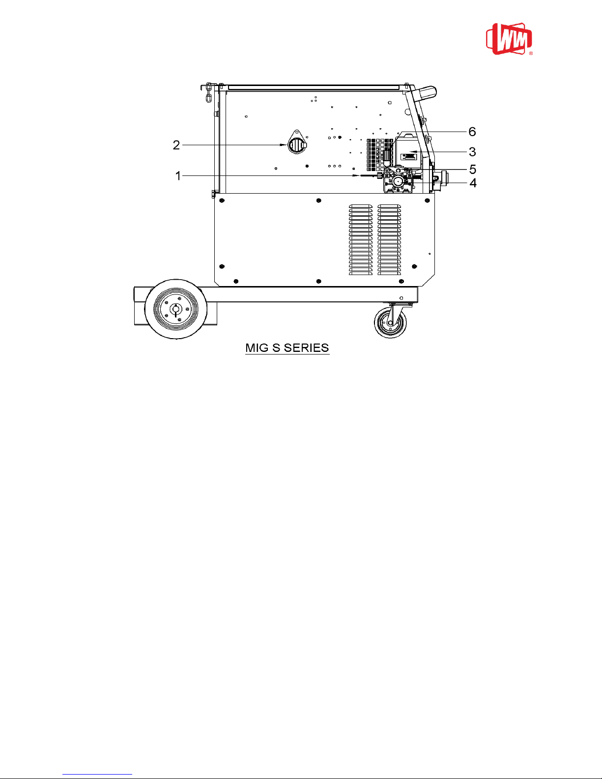
A few minutes spent reading about your
new MIG S Series welding machine will
enable you to operate your machine
efficiently and benefit from its many
features.
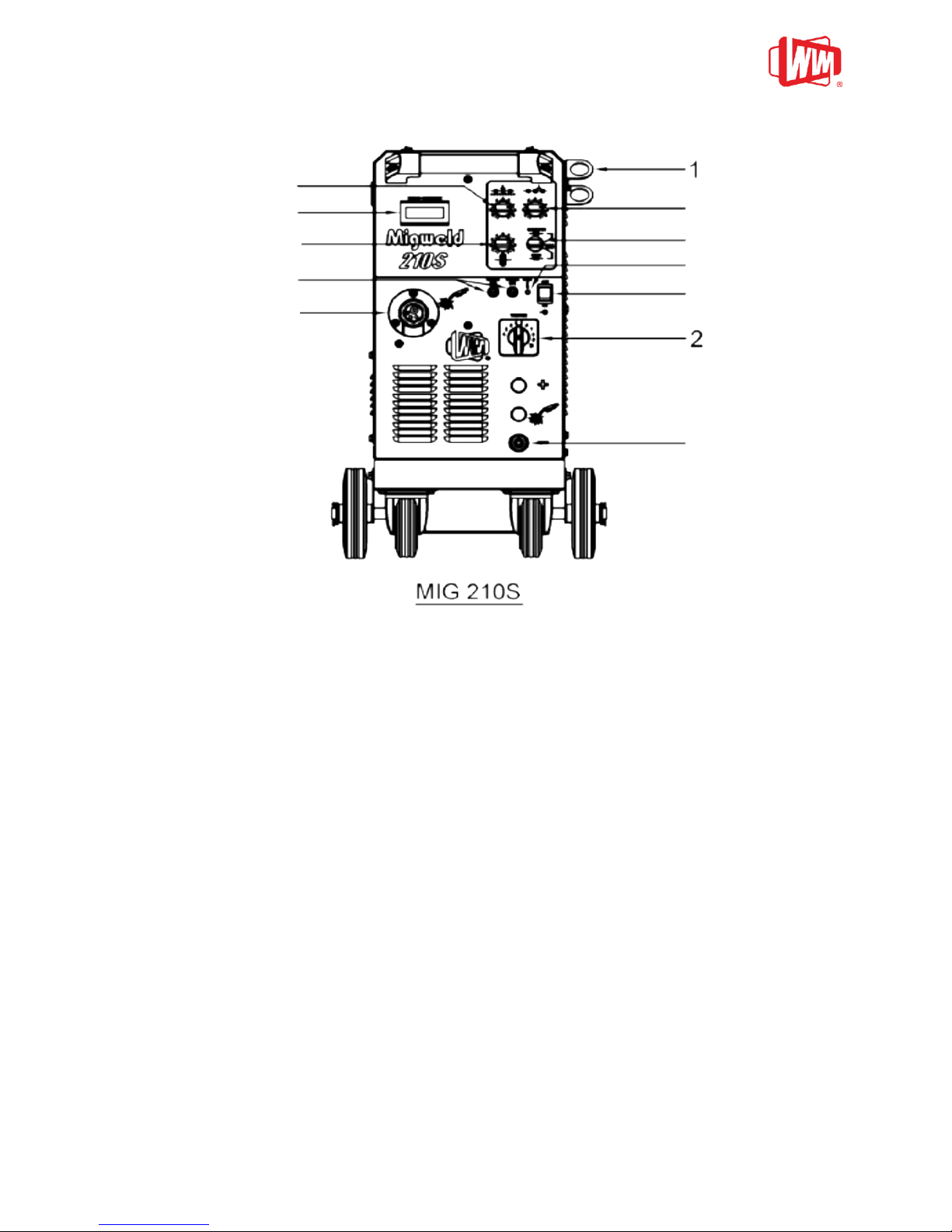
2. SETTING UP OPERATION
2.1 Fit Torch to Machine
Carefully align gas connection tube and
trigger connection pins with central
adaptor. Push in and tighten the lock nut.
Open the wire feed pressure arm above
the feed roll. Fit the feed roll to suit the
diameter of wire to be used.
2.2 Feed Roll Changing (if required)
Remove the feed roll-retaining knob. Pull
off feed roll. When replacing the feed roll,
note the wire size which is stamped on the
side face of the roll. The required size
must face inwards when the roll is refitted.
Ensure that the Woodruff Key is not lost.
Fit the feed roll and refit the retaining knob
using thumb and forefinger. Do not over
tighten.
2.3 Fit the Reel of Welding Wire
Turn the red plastic knob of the hub until
the concave is aligned with the black tip.
Place the reel of wire on hub so that the
wire will be drawn off from the bottom.
Ensure that the pin on the hub locates in
the hole in the side of the wire reel spool
reel. Turn the red plastic knob and make
sure the concave is not aligned with the
black tip. Use 300mm diameter 15kg
spools only.
WIRE
DIAMETER FE.
WIRE MM
WIRE GUIDE
LINER INT.
DIAMETER MM
Dia. 0.8 - 1.2
Dia. 1.6
Dia. 1.0-1.5
Dia. 2.0
WIRE
DIAMETER AL.
WIRE MM
WIRE GUIDE
LINER INT.
DIAMETER MM
Dia. 0.8
Dia. 1.0
Dia. 1.2
Dia. 1.5
Dia. 1.5
Remove the red plastic knob. Tighten or
unscrew the hub tension hand nut in the
centre of the hub reel assembly until
sufficient hub friction is achieved to
prevent overrun. This adjustment should
be done with full spool of wire at maximum
wire feed speed. Do not over tighten.
2.4 Wire Feeding
Release the wire end from reel and cut off
the bent wire end, taking care that the wire
does not unwind. Remove the nozzle and
contact tip from the welding gun.
Straighten about 10cm of the wire and
make sure that the end is as blunt as
possible (file off if necessary). A sharp end
could damage the cable liner and the
contact tip of the welding torch. Ensure the
wire is placed correctly on to the feed rolls.
Thread some wire through the feed rolls
into the guide tube and liner of the welding
cable. Close the wire feed pressure arm.
The pressure adjustment of the feed rolls
must be set so that the wire is fed evenly
into the liner and light restriction of the wire
can be made without feed rolls slipping.
Note: Excessive pressure will cause
flattening of the wire, loosening of the
wire coating and undue wear of the
rolls.
2.6 Earth Connection
The earth connection from the welder
should at all times be made directly on to
the piece to be welded. The contact
between the earth and the job should be
as large and flat as possible. All rust and
paint on the work piece should be
removed
2.7 Gas Connection
Fit hose tail and nut to the gas hose and
hold captive with the hose clamp.
Connect the gas hose to the regulator,
open the cylinder valve and the gas flow
rate is automatically set to 15 liters per
minute.
NOTE: PLUG TOP MUST BE FITTED
BY A QUALIFIED ELECTRICIAN

© Welding Industries Malaysia Sdn. Bhd. reserves all rights even in the event of industrial property rights. We reserve all rights of disposal
such as copying and passing on to third parties. Specification may vary from country to country.
V1.1.07 4
3-0 MACHINE CONTROLS/CONNECTIONS
1. TORCH HOLDER FIT ON THE SIDE COVER RIGHT AS POINT AT THE DRAWING
2. VOLTAGE SELECTOR SWITCH
- Coarse control 10 steps
3. ON/OFF SWITCH
- With this switch is in the ON position, power is applied to the fan and control circuits.
WARNING: This switch does not isolate the unit from the mains electrical supply.
4. DC AMMETER
- Show the welding current.
5. OVERHEAT INDICATOR (LED)
6. FUSES
7. NEGATIVE TERMINAL (CO2)
8. SPOT TIME ADJUSTOR
9. STITICH TIME ADJUSTOR
10. WIRE FEED SPEED ADJUSTOR
11. FUNCTION SELECTOR SWITCH
To select the modes of the machine i.e. continuous, spot or stitich.
12. CENTRAL ADAPTOR
3
4
5
6
8
7
9
10
11
12

© Welding Industries Malaysia Sdn. Bhd. reserves all rights even in the event of industrial property rights. We reserve all rights of disposal
such as copying and passing on to third parties. Specification may vary from country to country.
V1.1.07 5
3-1 INTERNAL VIEW/PART DESCRIPTION
1 INLET GUIDE TUBE
2 WIRE SPOOL
3 DC MOTOR
4 FEED ROLL SECURE KNOB
5 PRESSURE WHEEL AND ARM
6 TENSIONING KNOB

© Welding Industries Malaysia Sdn. Bhd. reserves all rights even in the event of industrial property rights. We reserve all rights of disposal
such as copying and passing on to third parties. Specification may vary from country to country.
V1.1.07 6
4-0 PARTS LIST
4-1 General View of MIG 210S
MIG 210S FINAL ASSEMBLY

© Welding Industries Malaysia Sdn. Bhd. reserves all rights even in the event of industrial property rights. We reserve all rights of disposal
such as copying and passing on to third parties. Specification may vary from country to country.
V1.1.07 7
4-2 MIG210S SPARE PARTS LIST
DWG
NO.
PART CODE
DESCRIPTION
QUANTITY
001
BKT-2520
NYLON SIDE HOLDER / BRACKET
2
002
STBH-SD32-218
TUBE: HADLE 1¼” (OD) X 1.2MM (T) X 218MM (L)
1
003
MTA-R075HB
DIGITAL DISPLAY METER HB5135BW DA400 75MV (HBKJ)
1
004
SCBA-MGV1-1
MIGWELD-VR P.C ASSEMBLY BOARD
1
005
EVAO-KN00
VOLUME KNOB (MO-895/T)
4
006
ESWO-1550
ON/OFF SWITCH C1550VQ (ROCKET SWITCHES)
1
007
ELED-001H
LED HOLDER
1
008
EFUH-B001
FUSE HOLDER (BIG)
2
009
EFUS-0030-CE
GLASS FUSE 3A 250V MGC 6.35X31.75MM (F) WALTER
1
010
EFUS-0050
GLASS FUSE MRS 5A 250V (UL/CSA)
1
011
THA-I001
MIG TORCH ADAPTOR INSULATOR
1
012
THA-U001
(501.2364) CENTRAL ADAPTOR 3E+UNIVERSAL
1
013
CVT-3923
PLASTIC COVER: (LL9X0.40) STEP SWITCH
1
014
SWS-NPH-M135
STEP SWITCH NO PLATE HANDLE
1
015
SSWS-PNP-M210
10 STEPS SWITCH P.C NO PLATE WITH VOLUME
1
016
SSWS-SWK-M135
STEP SWITCH KNOB WITH HEXAGON BRASS
1
017
SWS-SNH-M135
STEP SWITCH HANDLE
1
018
RBS-0002
PLASTIC STOPPER (OD 20.5MM)
2
019
SPS-CX30
PANEL SOCKET TEBM25 (10-25MM2)
1
020
SBKF-R100-1
FILTER TERMINAL SET MIGWELD SERIES
2
021
ELED-001R
L.E.D (RED)
1
022
REF-2500
RECTIFIER RADD PTS 290
1
023
SCBA-MGD2-1
MIGWELD-D2 P.C ASSEMBLY BOARD
1
024
CNB-0600
CONNECTOR: TERMINAL TEND (BLOCK) 10A
4
025
CNE-0600
CONNECTOR: TERMINAL TEND (BLOCK) 10A END PLATE
1
026
CCA-0240-12T
CONTACTOR: AC24V TMC-12 (3-1)
1
027
SCBA-MIGD-AV2
DIGITAL DISPLAY (V2) (MIGWELD)
1
028
WIS-1200-1
WIRE SPOOL 120MM (PLASTIC)
1
029
SRW-02R5-1450
SPRING; G12 (2.5MM) x 14MM x 5P x 25MM BL (SPOOL)
1
030
KNW-S001
KNOB: WIRE SPOOL (PLASTIC RED)
1
031
CPT-1802-500A
CAPACITOR ALU 18000UF 50V ALU-E/CAP
4

© Welding Industries Malaysia Sdn. Bhd. reserves all rights even in the event of industrial property rights. We reserve all rights of disposal
such as copying and passing on to third parties. Specification may vary from country to country.
V1.1.07 8
4-2 MIG210S SPARE PARTS LIST (Cont...)
DWG
NO.
PART CODE
DESCRIPTION
QUANTITY
032
NLP-8828-08R0
NYLON PLATE: 88 x 28 x 8MM
1
033
FDW-3110-4
WIRE FEED MECH CWF-3110-4 C/W MOTOR
1
034
ETMS-1010
THERMOTSTAT INTOIL C1010 0248AB
1
035
TRC-2303-012N
TRANS: IP(0-180-200-230) OP(0-7.5-12-0-12)
1
036
VVG-24AC-ZK
VALVE: GAS 24VAC
1
037
SHT-4000-75
SHUNT 400A 75MV
1
038
ERST-0270-100
RESISTOR 27OHM 10W (CR TYPE –H)
1
039
STRM-M21C-1
WELDING TRANSFORMER (C)
1
040
STRM-M210-2
MAIN WELDING TRANSFORMER
1
041
TBS-B228
RUBBER STOPPER B228
2
042
WLR-1020
4“SWIVEL CASTOR C/W BLACK RUBBER WHEEL
2
043
WLR-1600
6“BLACK RUBBER WHEEL (160MM x 21MM)
2
044
BWC-RAH-1238
BLOWER COOLING FAN RAH 1238B1 220-240VAC
50/60HZ
1
045
BWC-RAH-1751
BLOWER COOLING FAN (172 x 150 x 51MM)
1
046
HOB-P150
HOSE BINDER (PLASTIC) (AC200/500)
2
047
HOG-0060
RUBBER GAS HOSE 5MM
1
048
SWRH-KFA0-345
CABLE: FLEXIBLE 3C/110-0.193MM+13A PIN PLUG (345)
1
049
CNB-020A
CONNECTOR: TERMINAL BLOCK 20A (TBC-20-14)
5
050
CNE-0800
CONNECTOR: TERMINAL TEND (BLOCK) 20A END PLATE
1
051
ASSW-M210-2
10 POLES STEP SWITCH ASSEMBLY SET
1

© Welding Industries Malaysia Sdn. Bhd. reserves all rights even in the event of industrial property rights. We reserve all rights of disposal
such as copying and passing on to third parties. Specification may vary from country to country.
V1.1.07 9
5-0 CIRCUIT DIAGRAM
MIGWELD 210S BLOCK CIRCUIT DIAGRAM

© Welding Industries Malaysia Sdn. Bhd. reserves all rights even in the event of industrial property rights. We reserve all rights of disposal
such as copying and passing on to third parties. Specification may vary from country to country.
V1.1.07 10
6-0 WELDING TECHNIQUES
6-1 Setting of the Machine
The setting of a MIG S Series welding machine demands some practice from the welder, the
machine having two control points that have to conform. These two are the wire feed speed
and the welding voltage. The welding current is determined by the wire feed speed, and it
should correspond to the work piece. The current will increase wire speed, resulting in a
shorter arc. Less wire speed will reduce the current and lengthen the arc. Increasing the
welding voltage hardly alters the current intensity, but lengthens the arc. By decreasing the
voltage a shorter arc is obtained with little change in current intensity.
When using CO2 as shielding gas, increase the voltage by about 5 volts per 100 Amp.
When changing the wire diameters, different control settings are required. A thinner wire
needs more speed to acquire the same current strength. A satisfactory weld cannot be
obtained if extreme values are exceeded.
If the feed speed is too high for the welding voltage, blockage will occur in the torch as the
wire dips into the molten pool and does not melt. Welding in these conditions normally gives
faults due to lack of fusion. If, however, the welding voltage is too high, large drops will form
on the end of the wire, causing spatter. The correct setting of voltage and speed can be seen
in an even and calm arc.
6-2 Influence of the Welding Position
The position of the torch and the work piece is important for quality and appearance of the
seam.
The diagrams on the next page show some of the many possibilities and indicate
schematically the importance of these positions. In practice one of course uses all
combinations of welding positions, torch directions and positions of the work piece.
Together with the figures, the diagram may help when an estimation of the importance of
separate factors for welding quality is needed.
The terms drawing weld and thrusting weld mean:
Drawing weld: torch sloped in direction of weld.
Thrusting weld: torch sloped away from direction of weld.
Drawing weld is sometimes designated "dragging welding" and thrusting weld "stabbing
welding".
Thrusting weld
Drawing weld
Width of seam
Wider
Narrower
Upper bead
Smaller
Larger
Penetration
Decrease
Increase
Tendency to lack of fusion
Greater
Lesser

© Welding Industries Malaysia Sdn. Bhd. reserves all rights even in the event of industrial property rights. We reserve all rights of disposal
such as copying and passing on to third parties. Specification may vary from country to country.
V1.1.07 11

© Welding Industries Malaysia Sdn. Bhd. reserves all rights even in the event of industrial property rights. We reserve all rights of disposal
such as copying and passing on to third parties. Specification may vary from country to country.
V1.1.07 12
7-0 MAINTENANCE
7-1 Checking Items
The following items demand special attention:
(A) Wire feed unit.
This unit is to be checked regularly at the wire feed roller and the wire nozzles, as it is of great
importance for a satisfactory welding result and a minimum of wear and tear that the wire
passes through the mechanism without any deformations of the wire or the wire feed roller.
The wire nozzle should often be checked and changed if the copper coating of the wire is
damaged on its way through the nozzles. Copper dust may totally hinder free passage
through the wire liner.
A weekly check and cleaning of the nozzles as well as the wire feed roller is recommended.
(B) Welding hose.
Great care should be taken that the welding hose is not overloaded. It should not be pulled
over sharp edges, and other heavy machines should not run over it as it may damage the wire
lines. The hose should be dismantled every week and cleaned with dry air.
(C) Welding torch.
There are many parts in the welding torch that have to be cleaned regularly. The main ones
are the contact tip and the gas nozzle. During the welding process, these parts are
bombarded with spatter that sticks in the nozzles. This may disturb the shielding gas flowing
from the gas nozzle down to the molten pool. Otherwise, if the gas nozzle is blocked up with
spatter, there is a danger that short-circuits will occur between the contact tip and the gas
nozzle. The spatter should therefore be removed regularly and spatter remover applied in
order to prevent spatter from burning into the nozzles. During the cleaning process, the gas
nozzle is removed.
REMEMBER: DO NOT CLEAN BY BEATING THE TORCH.
(D) Power source.
The rectifier and transformer should be blown out with dry air occasionally; otherwise the air
circulation will be affected by the dust.

© Welding Industries Malaysia Sdn. Bhd. reserves all rights even in the event of industrial property rights. We reserve all rights of disposal
such as copying and passing on to third parties. Specification may vary from country to country.
V1.1.07 13
8-0 TROUBLESHOOTING
Table 1: Common Faults
No.
FAULT
PROBABLE CAUSE AND REMEDY
1
Too little welding effect.
The welding seam
forms a bead.
1) One of the three fuses in the main switch is not working
(one phase is missing).
2) The welding voltage is too low.
Switch one setting higher.
2
The wire feed is
blocking.
1) The inlet nozzle and the wire are not in alignment with
each other.
2) The reel of wire is too taut; the wire must come off the
reel evenly.
3) The inlet or contact tip is worn out or is blocked up.
4) The welding wire is not clean or it is rusty. It could
also be of an inferior quality.
5) The pressure roller has to be tightened.
3
Spatter
1) The wire feed is too fast for the voltage setting.
2) Worn out contact tip.
4
Porous weld. A cone is
formed when spot
welding
1) Insufficient gas-not enough pressure or the cylinder is
empty.
2) Contact tip is blocked up.
3) Leakage-air is pumped in and dilutes the shielding gas.
5
The arc does not look
normal, and there is a
lot of spatter.
1) The material is dirty, under sealed or paint.
6
The wire keeps sticking
in the contact tip and is
very slow.
1) The wire can be malformed. The damage wire should be
cut off, pulled out and replaced. The pressure on the
wire feed roller should be checked.
2) Worn out contact tip.
7
No welding voltage
1)Working voltage interrupted due to overloading of the
transformer. Automatic switch on after cooling (15-30 min.)
Table 2: Troubleshooting for MIG S SERIES P.C. Assembly Board
No.
Trouble
PROBABLE CAUSE
1
Motor automatic work
a) Transistor 2SA1215 (MOSFETS)
2
Motor does not work
a) VR2 (B10K) Damage (Open circuit, short
circuit or broken pin).
b) Transistor BC557 (Q5) open circuit.
c) Transistor 2SA1215(MOSFETS)
d) Selector switch damage.
e) Resistor 10W 0.68 Ohm open circuit.
3
Spot & stitch time is short
a) VR1 (B250K) damage (Open circuit, short
circuit or broken pin).
4
Motor can not stop
a) Resistor 5W 0.68-Ohm (R3) open circuit.
5
Motor speed is slow
a) Transistor 2SA1215(MOSFETS)
b) VR2 (B10K) leaking.
6
Contactor's malfunction
a) Zener diode 24V 1/2W (ZD4) open circuit.
b) Transistor BC547 (Q11) short circuit.
7
Contactor does not work
a) TRIACS BTA10 600C (T1) open circuit.

© Welding Industries Malaysia Sdn. Bhd. reserves all rights even in the event of industrial property rights. We reserve all rights of disposal
such as copying and passing on to third parties. Specification may vary from country to country.
V1.1.07 14
9-0 TECHNICAL DATA
MODEL
MIG210S
Main Supply
1 - PHASE 50/60HZ
Voltage
220V ~ 240V
Max Input Current
33A
Fuse (slow)
35A
Cable Cross –Section Area
4 ~ 10mm2
Output Rating
210A / 24V
Duty Cycle %
30%
Rating 60%
145A / 21V
Rating 100%
110A / 20V
Voltage Adjustment
10 steps
Open Circuit Voltage
18V ~ 45V
Max Welding Output
210A / 24.5V
Min Welding Output
30A / 15.5V
Filler Wire Dimensions
0.6 ~ 1.0 Ømm
Wire Feeding Speed
1 ~ 17m/min
Timer (Spot or Stitch Welding)
0 ~ 5 sec
Static Characteristic
Flat (CV)
Dimension (L x W x H)mm
820 x 450 x 720
Weight
72kg
Insulation Class
H180°C
Degree of Protection
IPS21

© Welding Industries Malaysia Sdn. Bhd. reserves all rights even in the event of industrial property rights. We reserve all rights of disposal
such as copying and passing on to third parties. Specification may vary from country to country.
V1.1.07 15
10-0 SAFETY OBSERVATION
Support the gas cylinder
with chain provided in the
machine
Protect eyes and open cylinder
valve to remove any dirt in valve
socket.
Fit gas regulator to cylinder
head and tighten using correct
size spanner. OVERTIGHTEN
will cause ‘O’ RING in the
regulator to spoil.
Open cylinder valve and
check the cylinder valve
pressure ( Must be greater
than 10bar 150Ib/in2)
Shut the cylinder valve.
Fit gas hose to regulator and
open cylinder valve. Set flow
15Lt Min. Bigger torch may
need 20Lt Min.
Clean the material to be
welded with a wire brush.
Place the earth lead clamp on a
clean area of the work piece.
Keep the gap between pieces
to be welded to a minimum.
Ensure a fire
extinguisher is
nearby in case
of fire.
Clean the welding
area and check a fire
extinguisher is
available.

© Welding Industries Malaysia Sdn. Bhd. reserves all rights even in the event of industrial property rights. We reserve all rights of disposal
such as copying and passing on to third parties. Specification may vary from country to country.
V1.1.07 16
10-0 SAFETY OBSERVATION ( Cont’d)
Handing
Remove cylinder before lifting
Handing
Do not lift using handle
Handing
Lift the unit correctly
Heat
Do not burn yourself!
Wear gauntlets and use tongs
Glare
Wear your headshield ( or face
screen) and screen the welding
area
Fume
Ventilate the welding area to
prevent build-up of gas and
fume
Dress
Dress correctly when welding and
preparing the weld
Dust
Note: Use only DRY air at a pressure not
exceeding 2 bar
Wear goggles and mask when
removing dust with an airline
Fire
Before commencing welding,
clear the flammable area
Electrical
Do not work with cover off
Leave it to the experts
Electrical
415/230 A.C is supplied to the
p.c.b Isolate unit before
removing covers of p.c.b
Electrical
Do not allow leads to lie in oil,
water or corrosive liquid or
extend them with extension
leads-fit a longer cable
Torch lead
draped over
shoulder
Dark,
high
necked
overall
with
buttoned
cuffs
Correct Grade
of glass
(Ew9, 10&11)
Clear Goggles
for chipping
and wire
brushing
Leather gauntlets

© Welding Industries Malaysia Sdn. Bhd. reserves all rights even in the event of industrial property rights. We reserve all rights of disposal
such as copying and passing on to third parties. Specification may vary from country to country.
V1.1.07 17
THE WIM GENERAL WARRANTY
Your welding machine is warranted by WIM to be of satisfactory quality, fit for its purpose and to comply with applicable WIM
specification for a period of twelve (12) months from the date of purchase (verified by reference to your proof of purchase). Not
applicable for consumable parts and accessories.
This warranty does not apply if the welding machine has:
a) Been mishandled, misused, willfully damaged, neglected, improperly tested, repaired by unauthorized person, altered or
defaced in any way.
b) A defect arising as a result of any failure to follow instructions either on the manual or product specification.
c) A defect which has arisen from the use of non-WIM approved accessories or ancillary items attached to or in connection
with the welding machine.
d) The warranty sticker removed or tempered with.
The manufacturer reserves the right to:
a) Make changes in technical and product specification without prior notice.
b) Waive the warranty on visual defect not reported within seven (7) working days.
JAMINAN AM WIM
Mesin kimpalan anda dijamin oleh WIM untuk kualiti yang memuaskan, sesuai digunakan untuk tujuan dan mengikut spesifikasi WIM
untuk tempoh dua belas (12) bulan dari tarikh pembelian (disahkan melalui bukti resit pembelian anda.) Syarat ini tidak termasuk
pada barangan guna habis dan aksesori.
Jaminan ini tidak boleh dituntut jika didapati mesin kimpalan anda telah:
a) Salah penyelengaraan, disalahgunakan, kerosakan yang disengajakan, kecuaian, ujian yang tidak dilakukan dengan betul,
dibaiki oleh orang yang tidak berkelayakan, diubahsuai atau dirosakan dengan apa cara sekalipun.
b) Kerosakan berlaku akibat dari kegagalan mematuhi arahan samaada dari manual atau spesifikasi produk.
c) Kerosakan berpunca dari penggunaan aksesori yang tidak mendapat pengesahan WIM atau barang sampingan yang
dipasang atau disambung pada mesin kimpalan anda.
d) Label jaminan telah ditanggalkan atau kotor.
Pihak pengilang berhak untuk:
a) Membuat sebarang pindaan teknikal dan spesifikasi produk tanpa sebarang notis.
b) Jaminan tidak boleh dituntut jika berlaku kerosakkan visual yang tidak dilaporkan dalam tempoh tujuh (7) hari bekerja.
WIM一般的保证书
由购买日期算起的十二个月内,(由购买证据所鉴定)WIM保证您的焊机品质令人满意,功能良好及附合WIM的相关规格。这保证不包含消
耗物品和配件。
这保证不包含以下情况之产品:
a) 焊机经过不适当的处理、误用、 蓄意毁坏、 疏忽、 不正确地做试验、没有经过WIM批准人员修理 、改造或磨灭。
b) 没有跟从手册或在产品规格里的指示所引起的缺点。
c) 使用没有得到WIM所批准的配件或跟焊机附著或连接的物品。
d) 保证贴纸已被移位或破坏。
厂商保留以下权力:
a) 在没有优先的通知下更改技术规格。
b) 在七个工作天内,外观不良必须提出,否则作废。

© Welding Industries Malaysia Sdn. Bhd. reserves all rights even in the event of industrial property rights. We reserve all rights of disposal
such as copying and passing on to third parties. Specification may vary from country to country.
V1.1.07 18
WIM MIG 01 WARRANTY
1) General: WIM products are warranted against manufacturing defects for one (1) year following
date of shipment to the original user. With exception of item listed in paragraphs 2 through 7
below.
2) Major Power Components: Main power transformers are warranted for two (2) years following
date of shipment to the original user. WIM will cover parts and labor in year one and
replacement only in year two,
3) Major Power Rectifiers: Silicon diodes and power SCRs used in the welding output circuit of
equipment are warranted for one year following date of shipment to the original user.
4) Major PCB Component: Main control board will be warranted for a period of one year from the
date of purchase (verified by reference to proof of purchase).
5) Expendable Items: Primary and secondary switch contacts, cable connectors, fuses, bulbs,
filter, ceramic nozzles, collets body, handle, leads connector and trigger switch are worn or
consumed in the normal process of welding or cutting and are therefore warranted only if
found to be defective prior to use.
6) Semiautomatic Item: Torch body and cable are warranted for fourteen (14) days from the date
of purchase (verified by reference to your proof of purchase).
7) Modification and Misuse: This warranty does not apply to products which have been modified
in any way by any party other than WIM: nor to products which have not been installed and
operated in accordance with applicable industry standards: nor to products which have been
used other than under the usual conditions for which designed: nor to products that have not
received proper care, lubrication, protection and maintenance under supervision of competent
personnel. Use of a product after discovery of a defect voids all warranties.
DISCLAIMER OF WARRANTIES
There are no warranties, which extend beyond the description on the face hereof, except as
specifically provided in the expressed warranties set forth above. All products are sold “as is”.
WIM makes no warranties, expressed or implied, of merchantability or fitness for a particular
purpose.
WARNING
At all times, safety is an important consideration in the installation, servicing, and operation of the
product, and skilled, qualified technical assistance should be utilized at all times. Specific
recommendations are included in instruction manual. The users are reminded to read carefully
the steps before carrying out welding jobs.

© Welding Industries Malaysia Sdn. Bhd. reserves all rights even in the event of industrial property rights. We reserve all rights of disposal
such as copying and passing on to third parties. Specification may vary from country to country.
V1.1.07 19
JAMINAN SIRI MIG WIM
1) Secara am: Produk WIM diberi jaminan selama satu (1) tahun dari tarikh pembelian oleh
pengguna. Pengecualian pada barangan yang terdapat pada perenggan 2 hingga 7 dibawah.
2) Komponen Kuasa Utama: Transformer kuasa utama diberi jaminan selama dua (2) tahun dari
tarikh pembelian oleh pengguna. WIM akan membiayai kedua-dua kos komponen gantian dan
penyelenggaran perkhidmatan pada tahun pertama dan hanya membiayai kos komponen
gantian pada tahun kedua.
3) Komponen Kuasa Rectifiers: Silicon diodes dan kuasa SCRs digunakan dalam peralatan litar
ouput kimpalan diberi jaminan selama satu (1) tahun dari tarikh pembelian pengguna.
4) Komponen Utama PCB: Main control board diberi jaminan satu (1) tahun dari tarikh
pembelian (disahkan melalui resit pembelian).
5) Komponen Guna Habis: Suis konteks primer dan sekunder, kabel penyambung, fius, mentol,
filter, ceramic nozzle, collects body, gas nozzle, contact tip, gas diffuser, handle, lead
connector dan trigger switch yang rosak atau habis guna dalam proses normal kimpalan atau
pemotongan hanya diberi jaminan jika didapati kerosakan berlaku sebelum digunakan.
6) Barangan separa automatic; Torch Body dan kabel diberi jaminan selama empat belas (14)
hari dari tarikh pembelian( disahkan melalui resit pembelian).
7) Pengubahsuaian dan penyalahgunaan: Jaminan tidak diberikan pada produk yang telah
diubahsuai dengan apa cara sekalipun oleh mana-mana pihak selain dari pihak WIM; atau
produk yang tidak dipasang dan beroperasi seperti mana bersesuaian dengan piawaian
industri; atau produk telah digunakan luar dari kebiasaan ia direkabentuk, atau produk
tersebut tidak diberi penjagaan dengan betul, minyak pelinciran, kawalan dan
penyelenggaraan serta penyeliaan yang cekap oleh orang yang berkelayakan. Penggunaan
produk yang telah didapati rosak akan membatalkan semua jaminan yang diberikan
JAMINAN YANG TIDAK BOLEH DITUNTUT
Tidak ada jaminan melebihi dari apa yang dinyatakan kecuali tertera secara spesifik di atas.
Semua produk dijual “ dengan apa yang ada”. WIM tidak memberi jaminan, menyatakan dengan
jelas atau tidak langsung tentang jualan atau kesesuaian untuk tujuan tertentu.
AMARAN
Setiap masa keselamatan merupakan faktor utama semasa pemasangan, servis dan
pengoperasian produk, kemahiran dan pembantu teknikal yang berkelayakan perlu diberi
keutamaan sepanjang masa. Cadangan khusus yang terdapat dalam “Manual Keselamatan”.
Semua penguna diingatkan supaya membaca dengan teliti semua langkah-langkah yang
dinyatakan sebelum memulakan kerja-kerja kimpalan.

© Welding Industries Malaysia Sdn. Bhd. reserves all rights even in the event of industrial property rights. We reserve all rights of disposal
such as copying and passing on to third parties. Specification may vary from country to country.
V1.1.07 20
(保证书)
1) 一般:除了以下第二至第七段所注明之项目,所有WIM之产品对制造上之不良享有一年之使用保
证,保用期限由交货至原有使用者之日期算起。
2) 主要的确电力元件:主变压器有二年的保证,由交货至原有使用者之日算起。在第一年,WIM所保
证的包括零件更 换和工钱,在第二年只保证零件更换。
3) 主要的电力整流器:在焊接输出的线路之硅二极体及SCR有一年的保证,由交货至原有使用者之日
算起.
4) 主要的电路板元件:主控制板从购买日期算起有一年保证.(由购买证据所鉴定)
5) 消耗品:开关接触器、电缆连接器、保险丝、灯泡、过滤器、陶瓷喷咀、筒夹、把手、插座和
触发开关在正常焊接或切割中会磨损或消耗,因此只有用前的不良可享有保证.
6) 半自动项目:焊枪体和电缆从购买日期算起有十四天保证.(由购买证据所鉴定)
7) 修改和误用:这保证不含包以下情况之产品:(a)经过WIM以外的团体或个人之修改,(b)没有按
照通用的工业标准来安装和操作,(c)没有在原有设计的寻常情况下使用,(d)没有在可胜任的
人监督下给予适当照顾、润滑 、保护和保养。
保 证 之 声 明
除了特别提供更新的明确说明保证,任何超出於此说明范围之情况皆不获保证.全部产品照原样出
售.对於其他特殊用途 WIM一概不作保证.
注 意
无时无刻,在安装、维修和操作本产品时.安全是一项很重要的考虑因素.应该时常利用合格的技术
援助.明确的建议已包含在附上的使用自手册里.在还没进行焊接工作之前使用者要记得仔细读预防
步骤.
Table of contents
Other Welding Industries Malaysia Welding System manuals
Popular Welding System manuals by other brands

Stealth
Stealth DIGI-ARC140ST DV operating instructions

Miller Electric
Miller Electric 22A owner's manual

BorMann
BorMann BBC7020 operating instructions

ESAB
ESAB MIG400iCCCV instruction manual

Chicago Electric
Chicago Electric 62486 Owner's manual & safety instructions

Campbell Hausfeld
Campbell Hausfeld WG204498AJ instruction sheet