INTRODUCTION
IOM-040 Page 4 of 10
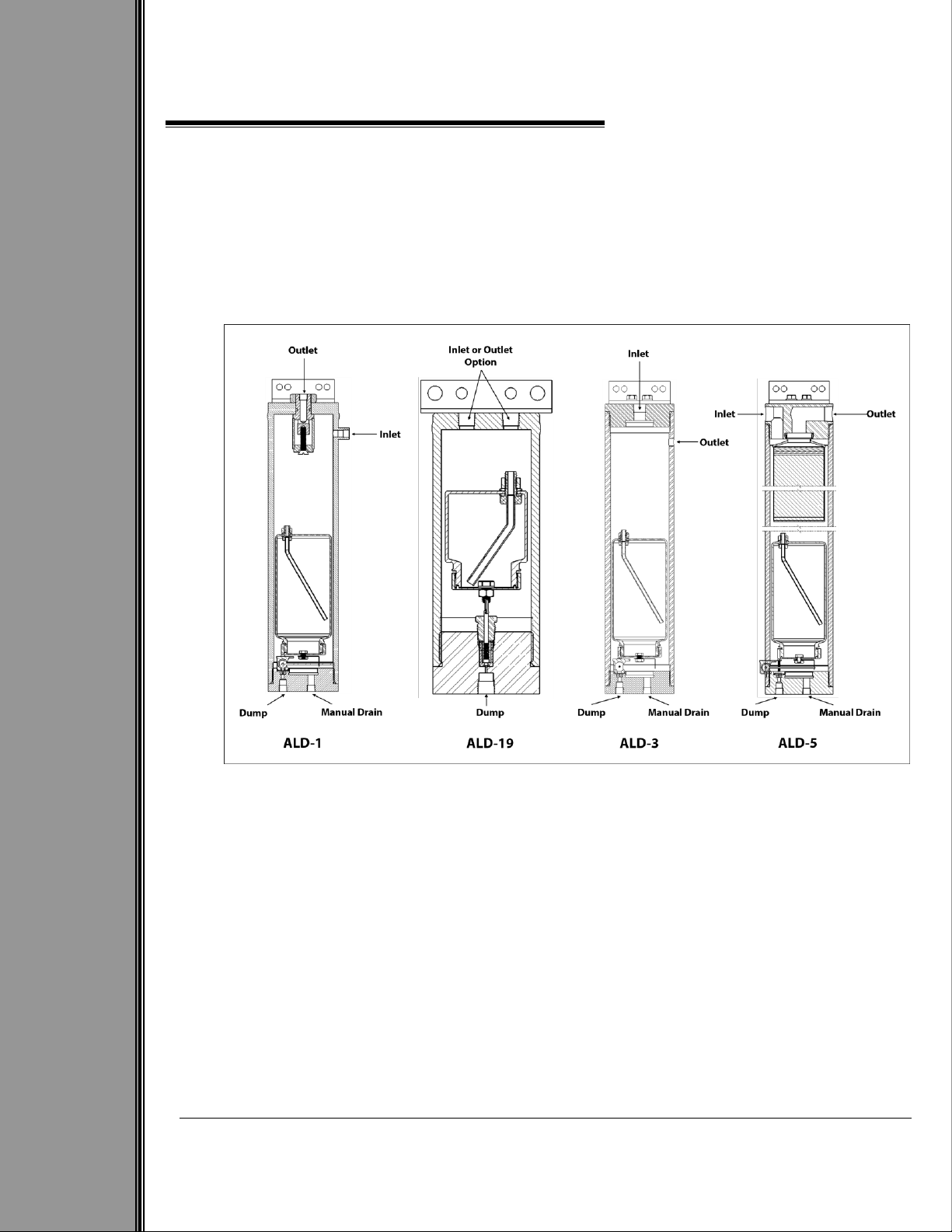
ALD-1, ALD-3, ALD-5, ALD-19
Rev: E
Last updated: 6/30/2023
1 GENERAL
1.1 Introduction
We appreciate your business and your choice of Welker products. The installation, operation, and
maintenance liability for this product becomes that of the purchaser at the time of receipt. Reading the
applicable Installation, Operation, and Maintenance (IOM) Manual prior to installation and operation of
this equipment is required for a full understanding of its application and performance prior to use. If you
have any questions, please call 1-800-776-7267 in the USA or 1-281-491-2331.
The following procedures have been written for use with standard Welker parts and equipment.
Assemblies that have been modified may have additional requirements and specifications that are not
listed in this manual.
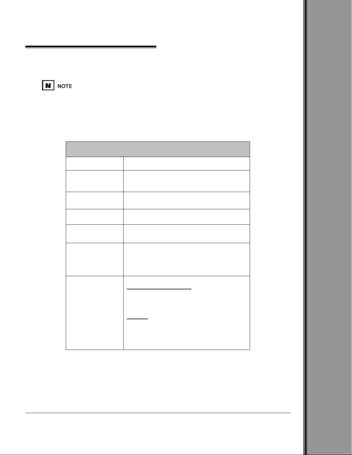
Notes, Warnings, and Cautions
Notes emphasize information or set it off from the surrounding text.
Caution messages appear before procedures that, if not observed, could result in
damage to equipment.
Warnings alert users to a specific procedure or practice that, if not followed
correctly, could cause personal injury.
1.2 Product Description
The Welker Automatic Liquid Dump is designed for use in systems where it is necessary to filter
entrained liquids from a process gas. A steady pressure is maintained from the supply source to the
instrumentation connected to the unit. As product enters the device, any free liquids are dropped to a
float at the bottom of the dump. A downcomer is installed inside the float, and as liquids fill the device,
the downcomer itself will begin to float. The downcomer is connected to the dump port, and eventually,
the buoyancy of the float will cause the downcomer to lift. When the downcomer lifts, it will open the
dump port, allowing the liquids to be drained.
The ALD-1 incorporates a coalescing device for product supply that is high in aerosols. The device will
coalesce the aerosols into liquid droplets, which will then drop around the float.