Welker INLOOP ACE User manual

INSTALLATION, OPERATION, ANDMAINTENANCEMANUAL
WELKER INLOOP™ ACE CRUDEOILSAMPLER
DRAWING NUMBER
AD905BQ
MANUAL NUMBER
IOM-224
REVISION
Rev. A, 8/8/2019

TABLEOFCONTENTS
2IOM-224 MODEL: INLOOP™ ACE REV: A 13839 West Bellfort Street, Sugar Land, TX 77498 welker.com Service Department 281.491.2331
Copyright © 2019Welker, Inc. All rights reserved. Welker®, W Welker®, W logo, WelkerScope®, WelkerJet®, and OdorEyes® are registered trademarks of Welker, Inc.
SAFETY 3
1. PRODUCT INFORMATION 4
1.1 Introduction 4
1.2 Product Description 4
1.3 Specifications 5
1.4 Equipment Diagrams 6
2. INSTALLATION & OPERATION 11
2.1 Before You Begin 11
2.2 Installing the Unit 11
2.3 Operating the Unit 14
2.4 Verifying the Sample Volume 17
2.5 Purging the Unit 18
3. MAINTENANCE 19
3.1 Before You Begin 19
3.2 Maintenance 20
3.3 Troubleshooting 28
APPENDIX 30
A: Referenced or Attached Documents 30

IMPORTANTSAFETYINFORMATION
READALLINSTRUCTIONS
Notes emphasize information and/or provide additional information to assist the user.
Caution messages appear before procedures that could result in damage to equipment if not observed.
Warning messages appear before procedures that could result in personal injury if not observed.
This manual is intended to be used as a basic installation and operation guide for the Welker inLoop™ ACE Crude Oil Sampler. For comprehensive instructions,
please refer to the IOM Manuals for each individual component. A list of relevant component IOM Manuals is provided in Appendix A of this manual.
The information in this manual has been carefully checked for accuracy and is intended to be used as a guide for the installation, operation, and maintenance of
the Welker equipment described in this manual. Correct installation and operation, however, are the responsibility of the end user. Welker reserves the right to make
changes to this manual and all products in order to improve performance and reliability.
BEFOREYOUBEGIN
Read these instructions completely and carefully.
IMPORTANT- Save these instructions for local inspector's use.
IMPORTANT- Observe all governing codes and ordinances.
Note to Installer - Leave these instructions with the end user.
Note to End User - Keep these instructions for future reference.
Installation of this inLoop™ ACE Crude Oil Sampler is of a mechanical nature.
Proper installation is the responsibility of the installer. Product failure due to improper installation is not covered under the warranty.
If you received a damaged inLoop™ ACE Crude Oil Sampler, please contact a Welker representative immediately.
Phone: 281.491.2331
Address: 13839 West Bellfort Street
Sugar Land, TX 77498
SAFETY
3IOM-224 MODEL: INLOOP™ ACE REV: A 13839 West Bellfort Street, Sugar Land, TX 77498 welker.com Service Department 281.491.2331

1.1 Introduction
We appreciate your business and your choice of Welker products. The installation, operation, and maintenance liability for this
equipment becomes that of the purchaser at the time of receipt. Reading the applicable Installation, Operation, and
Maintenance (IOM) Manuals prior to installation and operation of this equipment is required for a full understanding of its
application and performance prior to use.*
If you have any questions, please call Welker at 1-281-491-2331.
*The following procedures have been written for use with standard Welker parts and equipment. Assemblies that have been modified may have additional
requirements and specifications that are not listed in this manual.
1.2 Product Description
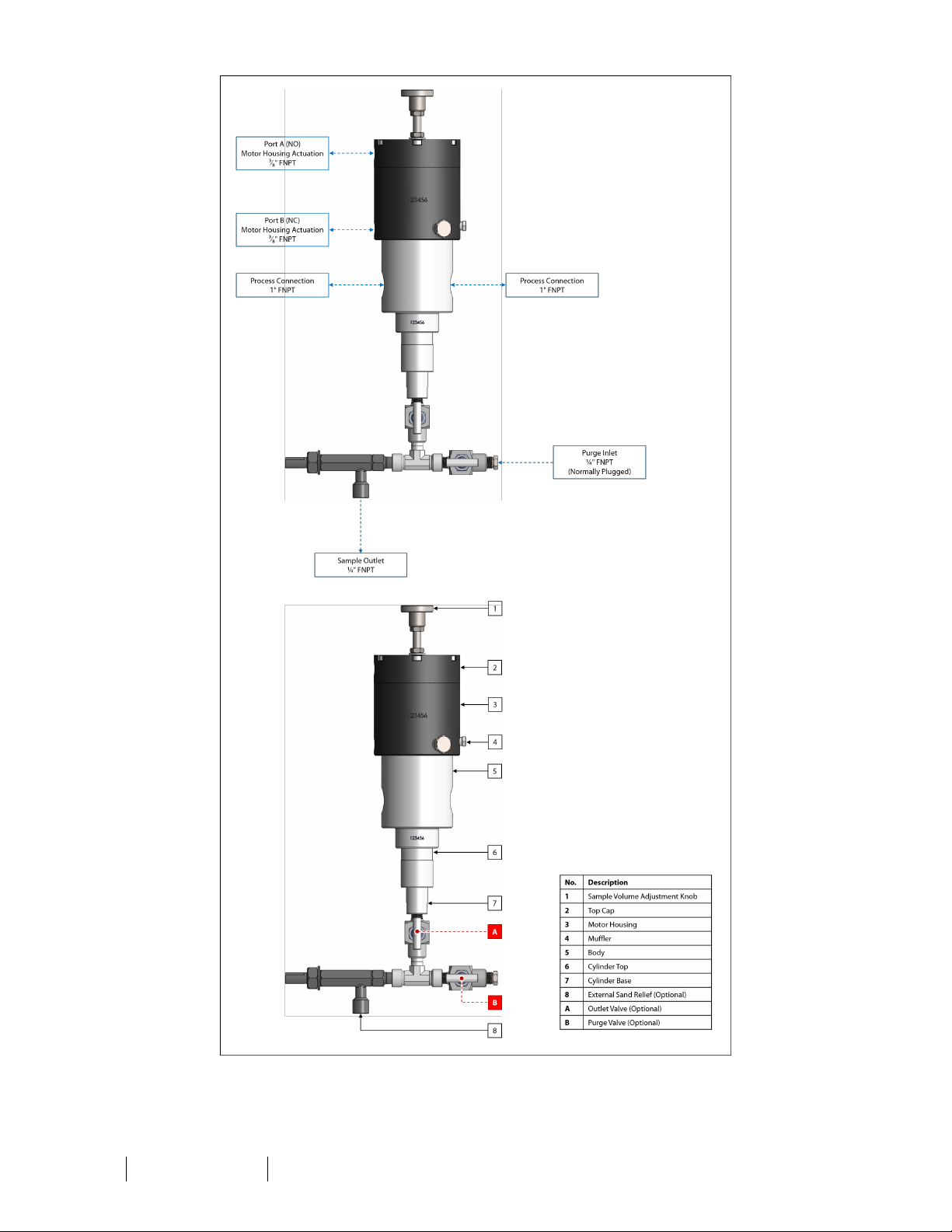
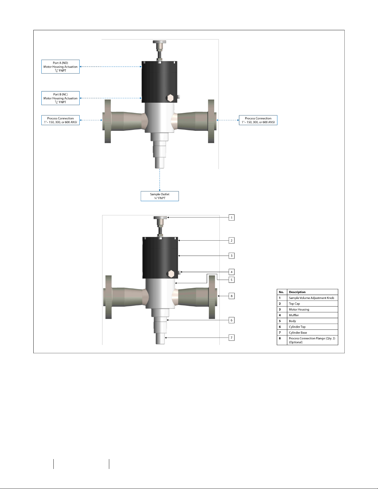
The Welker inLoop™ ACE Crude OilSampler is a bypass sampler designed to extract a representative sample of liquid product
from the flowing stream. With protection from internal check valves designed for sandy oils, this sampler is capable of sampling
product containing sand.
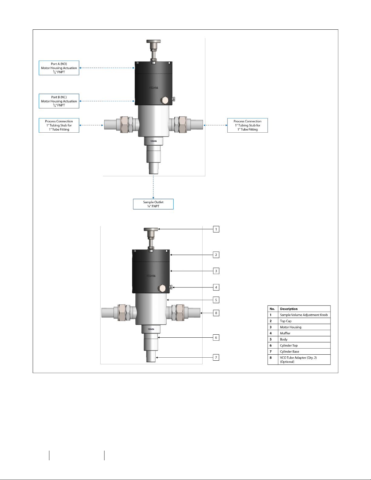
The inLoop™ ACE was specifically designed to be installed as part of a fast loop, which will provide the sampler with a
continuous supply of product. Sampling may be hydraulically or pneumatically operated but is electronically controlled from a
Programmable Logic Controller (PLC) or other signal control system. Sampling may be timed or proportional to flow.
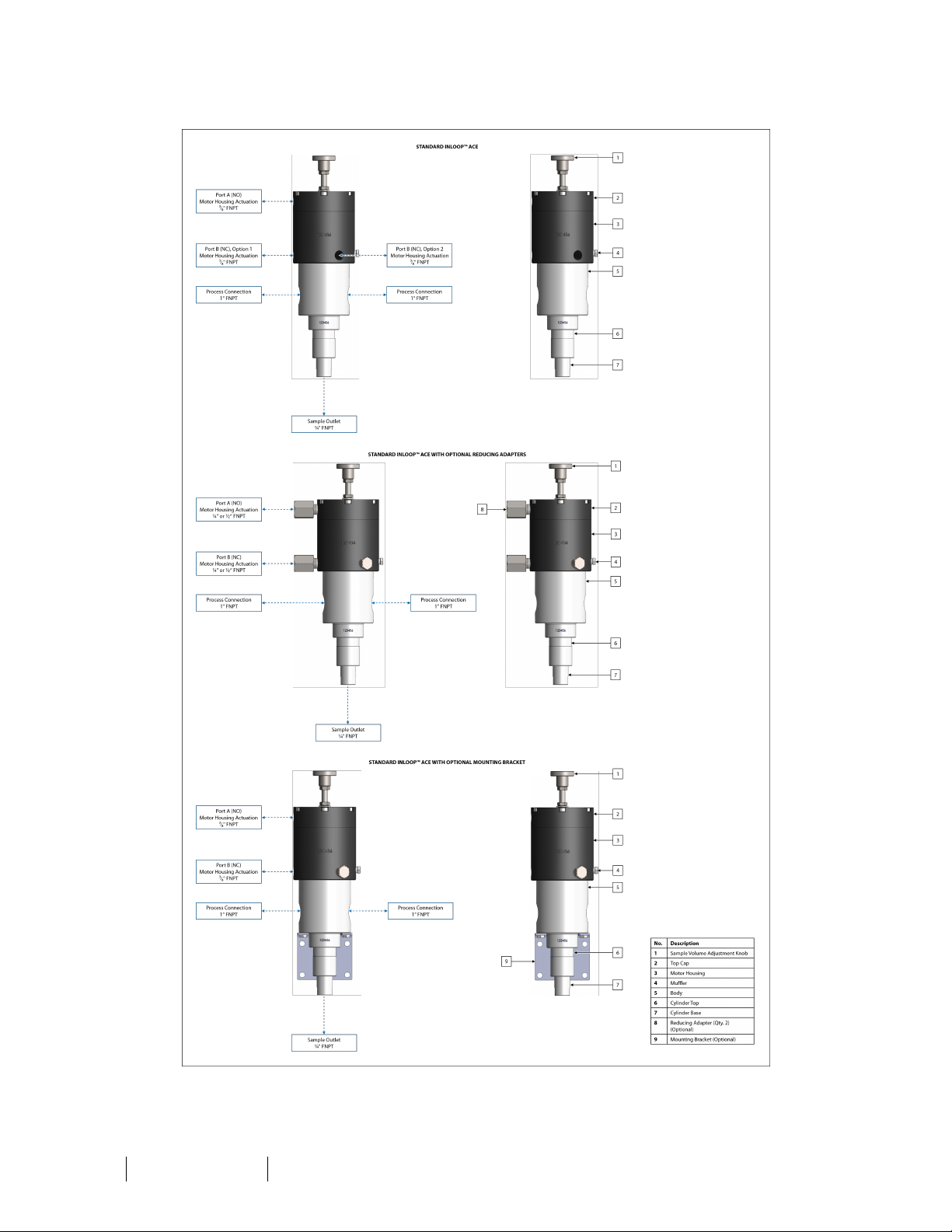
Designed with ease of use in mind, the external sample volume adjustment simplifies operation of the inLoop™ ACE even
further. The external adjustment allows the operator to adjust the sample volume without having to remove the inLoop™ ACE
from the fast loop.
For this manual, the term "PLC," or Programmable Logic Controller, will be used to refer to the PLC, DCS, or other signal control
system used by the customer to activate and operate the solenoid.
Welker may custom design the inLoop™ ACE to suit the particular application and specifications of each customer.
SECTION 1: PRODUCTINFORMATION
4IOM-224 MODEL: INLOOP™ ACE REV: A 13839 West Bellfort Street, Sugar Land, TX 77498 welker.com Service Department 281.491.2331

1.3 Specifications
The specifications listed in this section are generalized for this equipment. Welker can modify the equipment according to your
company's needs. Please note that the specifications may vary depending on the customization of your equipment.
Table 1: inLoop™ ACE Specifications
Application Bypass Sampling
Products Sampled Liquids Compatible With the Materials of Construction (See Figure 1)
Materials of Construction
316/316LStainless Steel Wetted Parts, Anodized Aluminum Non-Wetted Parts,
PTFE, and Viton®
Others Available
Maximum Allowable
Operating Pressure
FNPT or VCO: 1480 psig @ -20 °F to 100 °F (102 barg @ -28 °C to 37 °C)
150 ANSI Stainless Steel: 275 psig @ -20 °F to 100 °F (18 barg @ -28 °C to 37 °C)
300 ANSI Stainless Steel: 720 psig @ -20 °F to 100 °F (49 barg @ -28 °C to 37 °C)
600 ANSI Stainless Steel: 1440 psig @ -20 °F to 100 °F (99 barg @ -28 °C to 37 °C)
Fast Loop Connection
1" FNPT (Standard)
1" VCOFittings
1" – 150, 300, or 600 ANSIFlanges
Sample Outlet Connection ¼" FNPT
Motor Housing Actuation Ports
¼" FNPT
½" FNPT
³⁄₈" FNPT (Standard)
Utility Requirement Hydraulic or Pneumatic Supply for Motor Operation: 5–200 psig (0.3–13.7 barg)
Sample Volume 0.5–5 cc (Adjustable)
Features
External Sample Volume Adjustment
Internal Inlet Check Valve
Internal Outlet CheckValve
Options
External Sand Relief
Panel Mounting Bracket
Purge With Valve
Figure 1: Minimum Product Inlet Pressure Graph
5IOM-224 MODEL: INLOOP™ ACE REV: A 13839 West Bellfort Street, Sugar Land, TX 77498 welker.com Service Department 281.491.2331

1.4 Equipment Diagrams
Figure 2: Standard inLoop™ ACE Diagram
6IOM-224 MODEL: INLOOP™ ACE REV: A 13839 West Bellfort Street, Sugar Land, TX 77498 welker.com Service Department 281.491.2331

Figure 3: inLoop™ ACE With Optional External Sand Relief Diagram
7IOM-224 MODEL: INLOOP™ ACE REV: A 13839 West Bellfort Street, Sugar Land, TX 77498 welker.com Service Department 281.491.2331

Figure 4: inLoop™ ACE With Optional Purge Diagram
8IOM-224 MODEL: INLOOP™ ACE REV: A 13839 West Bellfort Street, Sugar Land, TX 77498 welker.com Service Department 281.491.2331

Figure 5: inLoop™ ACE With Optional VCOConnection Diagram
9IOM-224 MODEL: INLOOP™ ACE REV: A 13839 West Bellfort Street, Sugar Land, TX 77498 welker.com Service Department 281.491.2331

Figure 6: inLoop™ ACE With Optional Flanged Connection Diagram
10 IOM-224 MODEL: INLOOP™ ACE REV: A 13839 West Bellfort Street, Sugar Land, TX 77498 welker.com Service Department 281.491.2331

2.1 Before You Begin
After unpacking the unit, check the equipment for compliance and any damage that may have occurred during shipment.
Immediately contact a Welker representative if you received damaged equipment.
When sealing fittings with PTFE tape, refer to the proper sealing instructions for the brand used.
2.2 Installing the Unit
Note the inLoop™ ACE is bidirectional.
1. Depressurize the fast loop.
The fast loop must be depressurized prior to installing and removing the unit.
2. If the inLoop™ ACE has an FNPT or VCO process connection, continue to step 3. If the inLoop™ ACE has a flanged
process connection, proceed to step 6.
FNPT or VCOProcess Connection
3. Using 1" tubing or pipe, connect from the fast loop to the process inlet on the inLoop™ ACE (Figure 2, Figure 3, Figure 4,
or Figure 5).
4. Using 1" tubing or pipe, connect from the process outlet on the inLoop™ ACE to the fast loop (Figure 2, Figure 3, Figure
4, or Figure 5).
5. Proceed to step 15.
Flanged Process Connection
6. Position an appropriately sized gasket on one mating flange connection (Figure 6).
7. Install one flange of the inLoop™ ACE to the first mating flange connection.
8. Following a cross-bolting sequence, install bolts and nuts to the flanges.
9. Tighten all bolts to the appropriate torque.
10. Position an appropriately sized gasket on the other mating flange connection (Figure 6).
11. Install the other flange of the inLoop™ ACE to the second mating flange connection.
12. Following a cross-bolting sequence, install bolts and nuts to the flanges.
13. Tighten all bolts to the appropriate torque.
14. Continue to step 15.
SECTION 2: INSTALLATION&OPERATION
11 IOM-224 MODEL: INLOOP™ ACE REV: A 13839 West Bellfort Street, Sugar Land, TX 77498 welker.com Service Department 281.491.2331

Completing Installation
15. Using appropriately sized tubing, connect from the sample outlet to an appropriate customer-supplied sample
container, such as a Welker TCCTransportable Crude Oil Container for crude oil or a Welker Constant Pressure Cylinder
for light liquids (Figure 2, Figure 3, Figure 4, Figure 5, or Figure 6 and Table 2).
If the inLoop™ ACE is not equipped with a valve on the sample outlet, Welker recommends installing a valve to the sample
outlet. This will be outlet valve A.
Table 2: Recommended Tubing Size – Sample Container
Product Sampled Tubing Size
Light Liquids or Light Crude Oil Minimum ¼"
Medium or Heavy Crude Oil Minimum ³⁄₈"
Customer-supplied tubing must slope downward from the inLoop™ ACE to the sample container.
16. Using appropriately sized tubing, connect from the normally open port on the solenoid to port A on the motor housing
(Figure 2, Figure 3, Figure 4, Figure 5, or Figure 6 and Table 3). Using appropriately sized tubing, connect from the
normally closed port on the solenoid to port B on the motor housing (Figure 2, Figure 3, Figure 4, Figure 5, or Figure 6
and Table 3).
Table 3: Recommended Tubing Size – Motor Operation
Utility Supply for Motor Operation Tubing Size
Pneumatics Minimum ¼"
Hydraulics Minimum ³⁄₈"
17. If applicable, ensure that outlet valve A is closed (Figure 3 or Figure 4).
18. If applicable, ensure that the optional external sand relief has been set (Figure 3 or Figure 4).
19. If applicable, ensure that the customer constant pressure cylinder has been pre-charged and that all cylinder valves are
closed.
20. Pressurize the fast loop.
21. Check for leaks and repair as necessary.
12 IOM-224 MODEL: INLOOP™ ACE REV: A 13839 West Bellfort Street, Sugar Land, TX 77498 welker.com Service Department 281.491.2331

22. As necessary, adjust the sample volume of the inLoop™ ACE (Figure 7).
Figure 7: External Sample Volume Adjustment
Loosen the jam nut on the adjustment screw.
To increase the volume, turn the adjustment knob clockwise.
To decrease the volume, turn the adjustment knob counterclockwise.
Tighten the jam nut on the adjusting screw to secure the adjusting screw at the desired volume.
Two (2)full rotations of the adjustment knob is approximately 1 cc.
Ensure that the jam nut is tightened to the fastener seal prior to beginning operation, as the pump will not operate correctly
unless the jam nut is properly tightened. A leak check may be performed to verify that the jam nut has been properly tightened.
Once the desired volume is set, the sample volume can be changed at any time externally without removing the inLoop™ ACE
from the fast loop.
Welker can pre-set the sample volume if noted at the time of order.
13 IOM-224 MODEL: INLOOP™ ACE REV: A 13839 West Bellfort Street, Sugar Land, TX 77498 welker.com Service Department 281.491.2331

2.3 Operating the Unit
1. Turn ONthe hydraulic or pneumatic supply.
2. As necessary, adjust the hydraulic or pneumatic supply to 5–200 psig (Figure 8).
Figure 8: Minimum Actuation Pressure Graph
14 IOM-224 MODEL: INLOOP™ ACE REV: A 13839 West Bellfort Street, Sugar Land, TX 77498 welker.com Service Department 281.491.2331

3. Set the actuation time based on process conditions (Table 4 or Table 5).
Table 4: Sample Outlet Pressure and Minimum Actuation Time
Minimum Actuation Time for 1 Stroke Sample Outlet Pressure (psig)
2 Seconds
25
50
100
200
300
400
500
600
700
800
900
1000
3 Seconds
1100
1200
1300
1400
1500
Table 5: Product Viscosity and Minimum Actuation Time
Minimum Actuation Time for 1 Stroke Product Viscosity (cP)
2 Seconds
1
100
200
300
400
600
800
1000
2000
3000
4000
3 Seconds
5000
6000
7000
8000
9000
10,000
15 IOM-224 MODEL: INLOOP™ ACE REV: A 13839 West Bellfort Street, Sugar Land, TX 77498 welker.com Service Department 281.491.2331

4. Set the timer or controller to actuate the solenoid at the desired sampling actuation frequency based on the sampling
equations provided(Figure 9).
Figure 9: Sampling Frequency Equations
Never fill the container above 80% of its capacity. Allow at least 20% room for product expansion should the container be
exposed to increased temperatures.
Note the 0.8 in Equation 1 represents the 80% volume limit for liquid sampling.
Note that the sample volume of the inLoop™ ACE is adjustable between 0.5–5 cc per actuation.
5. As necessary, turnon electrical power and activate the hydraulic or pneumatic supply to actuate the solenoid at the set
sampling frequency.
6. Collect a sample from the sample outlet to ensure that the sample volume collected is the same as the desired sample
volume. See Section 2.4, Verifying the Sample Volume, for instructions.
Welker recommends the Welker Checkpoint™ Sample Bite Verification Panel for use with this unit.
16 IOM-224 MODEL: INLOOP™ ACE REV: A 13839 West Bellfort Street, Sugar Land, TX 77498 welker.com Service Department 281.491.2331

2.4 Verifying the Sample Volume
Welker recommends the Welker Checkpoint™ Sample Bite Verification Panel for use with this unit.
1. Ensure that the Welker Checkpoint™ Sample Bite Verification Panel has been installed correctly. Refer to the Installation,
Operation, and Maintenance (IOM) Manual for the Checkpoint™ for installation instructions.
2. Using appropriately sized customer-supplied tubing, connect from the sample outlet on the inLoop™ ACE to the
sample inlet on the Checkpoint™ (Figure 2, Figure 3, Figure 4, Figure 5, or Figure 6).
3. Decide how many actuations will be made to verify the sample volume.
Welker recommends a minimum of ten (10) actuations to verify the sample volume.
4. Follow the instructions in the Installation, Operation, and Maintenance (IOM) Manual for the Checkpoint™ to complete
sample volume verification.
5. As necessary, adjust the sample volume (Figure 7).
Loosen the jam nut on the adjustment screw.
To increase the volume, turn the adjustment knob clockwise.
To decrease the volume, turn the adjustment knob counterclockwise.
Tighten the jam nut on the adjusting screw to secure the adjusting screw at the desired volume.
Two (2)full rotations of the adjustment knob is approximately 1 cc.
Ensure that the jam nut is tightened to the fastener seal prior to beginning operation, as the pump will not operate correctly
unless the jam nut is properly tightened. A leak check may be performed to verify that the jam nut has been properly tightened.
17 IOM-224 MODEL: INLOOP™ ACE REV: A 13839 West Bellfort Street, Sugar Land, TX 77498 welker.com Service Department 281.491.2331

2.5 Purging the Unit
Welker recommends the Welker PNPPlug & Purge Panel for use with this unit.
To prevent cross-contamination between samples, Welker recommends that the inLoop™ ACE be evacuated, or purged,
following each sample batch to inject all sampled product remaining in the unit into the sample container.
1. If the inLoop™ ACE is not equipped with the optional purge, Welker recommends installing a customer-supplied tee
fitting with valve(s) to the sample outlet so that the inLoop™ ACE can be purged (Figure 10).
Figure 10: Recommended Arrangement for Purge
2. Ensure that the Welker PNPPlug &Purge Panel has been installed correctly. Refer to the Installation, Operation, and
Maintenance (IOM) Manual for the PNP for installation instructions.
3. Using ¼" tubing, connect from the purge outlet on the PNP to purge valve B (Figure 10).
4. Ensure that an appropriate inert gas supply is connected to the PNP. As necessary, refer to the Installation, Operation,
and Maintenance (IOM) Manual for the PNP for instructions.
5. If applicable, ensure that the PNPpressure transmitter has been configured. As necessary, refer to the Installation,
Operation, and Maintenance (IOM) Manual for the PNP for instructions.
6. Set the purge pressure to a pressure appropriate for the sampling system. Refer to the Installation, Operation, and
Maintenance (IOM) Manual for the PNP for instructions.
7. Open purge valve B (Figure 10).
8. Follow the instructions in the Installation, Operation, and Maintenance (IOM) Manual for the PNPto complete the purge.
18 IOM-224 MODEL: INLOOP™ ACE REV: A 13839 West Bellfort Street, Sugar Land, TX 77498 welker.com Service Department 281.491.2331

3.1 Before You Begin
1. Welker recommends that the unit have standard yearly maintenance under normal operating conditions.
In cases of severe service, dirty conditions, excessive usage, or other unique applications that may lead to excess wear
on the unit, a more frequent maintenance schedule may be appropriate.
2. Welker recommends replacing the poppets in the internal check valves weekly or semi-annually, depending on sample
outlet pressure (Table 6). Note that sample rate and product abrasiveness also impact the frequency of poppet
replacement.
Table 6: Recommended Replacement Frequency – Poppets
Replacement Frequency Sample Outlet Pressure
Semi-annually 25–700 psig
Weekly 800–1500 psig
3. Prior to maintenance or disassembly of the unit, it is advisable to have a repair kit available for repairs of the system in
case of unexpected wear or faulty seals.
Straight threaded unions without lock washers have the potential to loosen over time due to vibration and/or other factors.
Welker recommends applying a medium strength thread-locking fluid to such unions during reassembly.
New seals supplied in spare parts kits should be lightly lubricated before being installed to ease the installation of the seals and
reduce the risk of damage when positioning them on parts. Wipe excess lubricant from the seals, as it may adversely affect
analytical instrument results.
For sample-exposed seals, Welker recommends non-hydrocarbon-based lubricants, such as Krytox®.
For non-sample-exposed seals, Welker recommends either non-hydrocarbon-based lubricants or silicone-based lubricants, such
as Molykote® 111.
After the seals are installed, the outer diameter of shafts and inner diameter of cylinders may be lubricated to allow smooth
transition of parts.
4. All maintenance and cleaning of the unit should be performed on a smooth, clean surface.
SECTION 3: MAINTENANCE
19 IOM-224 MODEL: INLOOP™ ACE REV: A 13839 West Bellfort Street, Sugar Land, TX 77498 welker.com Service Department 281.491.2331

20 IOM-224 MODEL: INLOOP™ ACE REV: A 13839 West Bellfort Street, Sugar Land, TX 77498 welker.com Service Department 281.491.2331
5. Welker recommends having the following tools available for maintenance. Please note that the exact tools required may
vary by model.
a. 6"–8" Crescent Wrench (Qty. 2)
b. 14" Crescent Wrench
c. Hex Key Set
d. Medium Strength Thread-locking Fluid
e. Needle Nose Pliers
f. Pipe Wrench
g. Rubber Mallet
h. Seal Pick
i. Snap Ring Pliers
3.2 Maintenance
The fast loop must be depressurized prior to installing and removing the unit.
If maintenance is to be performed on the fast loop, the inLoop™ ACE must first be removed from the fast loop. Failure to remove
the unit from the fast loop prior to performing maintenance could damage the unit.
1. Depressurize the fast loop.
2. Deactivate or turn OFF the hydraulic or pneumatic supply.
3. Depressurize, drain, and disconnect the hydraulic or pneumatic supply lines.
4. Disconnect the customer-supplied sample container from the sample outlet.
5. Disconnect the inLoop™ ACE from the fast loop.
6. As necessary, drain any remaining hydraulic oil from the motor housing.
7. Lay the inLoop™ ACE on a smooth, clean surface.
8. If the inLoop™ ACE is not equipped with optional equipment at the sample outlet, proceed to step 17. If the inLoop™
ACE is equipped with optional equipment at the sample outlet, continue to step 9.
Other manuals for INLOOP ACE
1
Table of contents
Other Welker Industrial Equipment manuals
Popular Industrial Equipment manuals by other brands

Kooltronic
Kooltronic KNHX38 Series Operator's manual

Sumake
Sumake ST-6608 manual

Interpump Group
Interpump Group W101 Instructions for use

RollSeal
RollSeal RS-200 installation manual

Siemens
Siemens LOHER DYNAVERT I 6SE03 installation instructions

Thunderstone
Thunderstone EZ Flow XR Operation & Remote Programming Instructions

ABB
ABB HT612474 Operation manual

IML
IML FastWheel Original operating instructions

Pack Line
Pack Line PXG PL700565 user manual

RINGSPANN
RINGSPANN Brake HW 145 FHM Installation and operating instructions

Walinga
Walinga CENTRAL-VAC AIR-PURGE installation manual

Phoenix Mecano
Phoenix Mecano PMZ10 installation manual