Welker CP-2G User manual

© Copyright 2008, Welker, Inc.
Installation, Operation, and
Maintenance Manual
Welker
®
Constant Pressure Cylinders with
Tracker Tube
Models
CP-2G, CP-5G, CP-35G, and
CP-2G with Premium Purge
The information in this manual has been carefully checked for accuracy and is intended to be used as a guide for
the installation, operation, and maintenance of the Welker equipment described above. Correct operating and/or
installation techniques, however, are the responsibility of the end user. Welker reserves the right to make changes
to this and all products in order to improve performance and reliability.
13839 West Bellfort
Sugar Land, TX 77498-1671
(281) 491-2331 - ffice
fficeffice
ffice
http://www.welker.com

TABLE OF CONTENTS
IOM-011 Page 2 of 20
CP2G, CP5G, CP35G
Rev: F
Last updated: 7/9/2018
1. SPECIFICATIONS 3
1.1 I
NTRODUCTION
3
1.2 D
ESCRIPTION OF
P
RODUCT
4
1.3 I
MPORTANT INFORMATION
5
2. INSTALLATION & OPERATIONS 7
2.1 I
MPORTANT
I
NFORMATION
7
2.2 P
RE
-C
HARGING THE
C
YLINDER
8
2.3 I
NSTALLATION
10
2.4 S
POT
S
AMPLING
10
2.5 C
ONTINUOUS
S
AMPLING
11
3. MAINTENANCE 13
3.1 G
ENERAL
13
3.2
M
AINTENANCE
P
ARTS
D
IAGRAM
14
3.3
D
ISASSEMBLY
14
3.4 M
AINTENANCE
1
3.5 R
EASSEMBLY
1
3. C
YLINDER
C
LEANING
17
SAFETY ISSUE WARNING FOR LIQUID
SAMPLE CYLINDERS 18
4. TROUBLE SHOOTING GUIDE 19
Welker
®
, Welker Jet
®
, and WelkerScope
®
are Registered Trademarks owned by Welker, Inc.

SPECIFICATIONS
IOM-011 Page 3 of 20
CP2G, CP5G, CP35G
Rev: F
Last updated: 7/9/2018
1.
SPECIFICATIONS
1.1 I
NTRODUCTION
We appreciate your business and your choice of Welker products. The installation,
operation, and maintenance liability for this product becomes that of the purchaser at the
time of receipt. Reading the applicable Installation, Operation, and Maintenance (IOM)
Manual prior to installation and operation of this equipment is required for a full
understanding of its application and performance prior to use. If you have any questions,
please call 1-800-776-7267 in the USA or 1-281-491-2331.
The following procedures have been written for use with standard Welker parts and
equipment. Assemblies that have been modified may have additional requirements and
specifications that are not listed in this manual.
Notes, Warnings, and Cautions
Notes emphasize information or set it off from the surrounding text.
Caution messages appear before procedures that, if not observed, could result in
damage to equipment.
Warnings alert users to a specific procedure or practice that, if not
followed correctly, could cause personal injury.

SPECIFICATIONS
IOM-011 Page 4 of 20
CP2G, CP5G, CP35G
Rev: F
Last updated: 7/9/2018
1.2 D
ESCRIPTION OF
P
RODUCT
The Constant Pressure Sample
Cylinder is designed for use in
systems where it is necessary to
extract and isolate accurate
product samples by maintaining
a steady pressure from the
pipeline to the cylinder. The
cylinders are equipped with a
magnetic indicator and a
graduated scale set to specify
the capacity of the device.
During continuous sampling,
when the magnetic indicator
reaches the 80% mark, all
sampling should be stopped. A
pneumatic supply pre-charges
the cylinder with pressure to
correspond with pipeline pressure. Pre-charging allows the sample to be transferred to the
cylinder without taking a pressure drop. An internal piston in the cylinder helps to purge
out air and contaminants prior to taking the sample by displacement.
During the purge process, the piston is pushed to the end of the cylinder, also preventing
any other possible contaminants from entering. Burst discs and gauges are also included
on each end cap of the device. In the event that the cylinder is overpressurized, these
discs will rupture, relieving excess pressure from the cylinder. CP-2 Premium Purge
model cylinders have valves built into the pre-charge and product end cap ports. They are
also included with product purge and pre-charge purge valves.
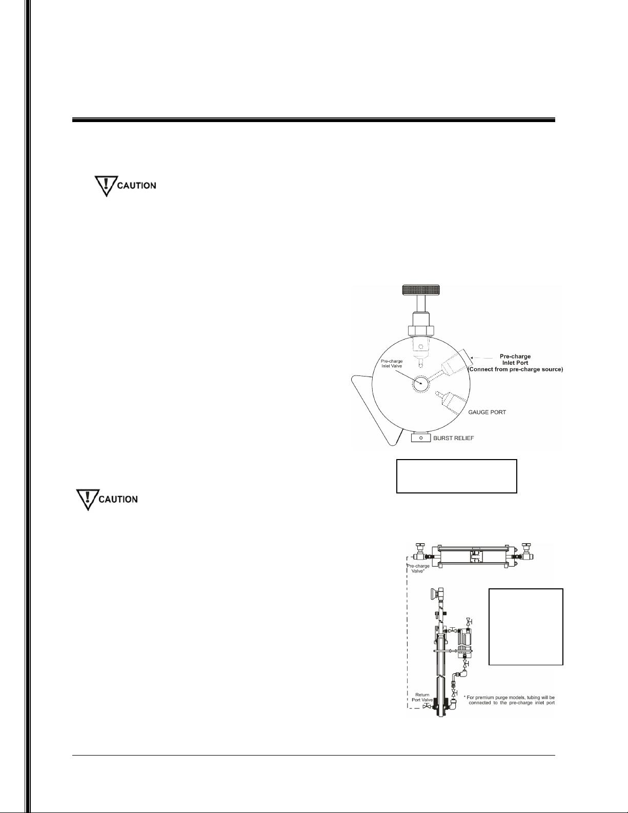
Adjustable relief valve (optional)
The adjustable relief valve functions as a safety device for the unit.
During continuous sampling and transportation of the cylinder, the
relief valve assures that the device maintains a constant pressure
and does not exceed maximum allowable pressure. The valve will
relieve any pressure that exceeds the set pressure.
Figure 2
Figure 1

SPECIFICATIONS
IOM-011 Page 5 of 20
CP2G, CP5G, CP35G
Rev: F
Last updated: 7/9/2018
1.3 I
MPORTANT INFORMATION
Please read the following information in its entirety upon receiving the Welker
equipment described above.
•Never fill a cylinder completely full of hydrocarbon liquid or refrigerated gas. Always
allow for at least 20% expansion.
•Never transport a cylinder with pressure exceeding D.O.T. regulations (see U.S.
Government CFR 49 for D.O.T. regulations). In cases where the cylinders are
exposed to varying temperatures, do not allow the cylinder to exceed the
maximum allowable operating pressure indicated in Table 1.
•Protect the cylinder at all times and handle with care. It is a precision instrument and
may contain a flammable or caustic product as well as a valuable representation of your
company’s product.
•When analysis is complete, the cylinder should be emptied safely and in a safe area by
opening the product inlet valve, allowing the pre-charge pressure to push the piston to
the product end cap, emptying the cylinder.
•Welker recommends cleaning and leak testing of the cylinders after each use.
•Because of the design of the cylinder and the incorporated seals, the process of
emptying the cylinder will simultaneously wipe the walls of the device clean. The end
cap will also be purged clean with the next use.
The specifications listed in this section are
generalized for this equipment. Welker can
modify the equipment according to your
company’s needs. However, please note that the
specifications may vary depending on the
customization of your product.
*Maximum allowable temperatures and pressures may be
lower depending on the specifications of the pipeline
connection device.
Table 1

SPECIFICATIONS
IOM-011 Page 6 of 20
CP2G, CP5G, CP35G
Rev: F
Last updated: 7/9/2018
1.3 I
MPORTANT INFORMATION
(C
ONTINUED
)
Refer to above diagram throughout manual

INSTALLATION & OPERATIONS
IOM-011 Page 7 of 20
CP2G, CP5G, CP35G
Rev: F
Last updated: 7/9/2018
2.
INSTALLATION
&
OPERATIONS
2.1 I
MPORTANT INFORMATION
•After unpacking the unit, check it for compliance and for any damages that may have
occurred during shipment.
•Claims for damages caused during shipping must be initiated by the receiver and
directed to the shipping carrier. Welker is not responsible for any damages caused from
mishandling by the shipping company.
•When sealing fittings with PTFE tape, refer to the proper sealing instructions for the
tape used.
•There are two ends to the cylinder, separated internally by a floating piston. One end is
marked PRODUCT INLET; this end can easily be identified by the blue vertical line on
the tracker tube. The other end of the cylinder is marked PRE-CHARGE END, and it
is marked on the tracker tube with a red vertical line at both 80% full and 100% full.
•A sample probe should be located in the least turbulent area available of the flowing
stream; i.e., not in a header or blow-down stack and away from obstructions, elbows or
partially closed valves. The sample probe should be installed reaching approximately
into the center one-third of the pipeline.
•The sample cylinder should be located as close to the sample point as is possible.
Recommended Tools
It would be advisable to have the following tools available for installation of the unit.
However, tools used will vary depending on cylinder model.
•Flexible hose or tubing
•6" adjustable wrench
•Tubing cutters
•Small diameter stainless steel tubing

INSTALLATION & OPERATIONS
IOM-011 Page 8 of 20
CP2G, CP5G, CP35G
Rev: F
Last updated: 7/9/2018
2.2 P
RE
-C
HARGING THE
C
YLINDER
The pre-charge gas being used must be compatible with the seals in the cylinder. The
relief valves and gauges must also be adequate for the pressures used when pre-
charging.
1. Connecting the cylinder pre-charge valve to the pipeline (pressurized gas pipeline
only):
•Use small diameter stainless steel tubing
to connect from an available pipeline valve
to the pre-charge inlet valve. If you have the
premium purge model, connect from the
pipeline valve to the pre-charge inlet port
(see Figure 3).
•Make sure all valves are closed on the
sample cylinder.
•Open the pipeline isolation valve.
•Slowly open the pre-charge inlet valve.
•Slowly open the product inlet valve to
relieve any pressure buildup. The piston will
begin to move.
Always open valves slowly to avoid slamming the piston from one end to the other.
•The pre-charge gauge should begin to read pressure
and will eventually reach pipeline pressure.
•Once the piston has reached the end of the cylinder,
close all valves and check for leaks.
•Disconnect the tubing from the cylinder and from
the pipeline isolation valve.
2. Connecting the pre-charge valve to the return
port on a sampler probe (for continuous
sampling):
•Install a valve into the return port of the sampler probe.
•Make sure all valves are closed on the sample cylinder.
Figure - 3 Pre-Charge
End Cap Detail
Figure 4 -
Connecting
Pre-Charge
Valve to
Return Port

INSTALLATION & OPERATIONS
IOM-011 Page 9 of 20
CP2G, CP5G, CP35G
Rev: F
Last updated: 7/9/2018
2.2 P
RE
-C
HARGING THE
C
YLINDER
(C
ONTINUED
)
•Use small diameter stainless steel tubing to connect from the cylinder’s pre-charge
inlet valve to the valve on the return port of the probe (see Figure 4). If you have the
premium purge model, connect from the sampler to the pre-charge inlet port (see
Figure 3).
•Open the valve on the return port of the sample probe.
•Slowly open the pre-charge inlet valve.
•Slowly open the product inlet valve to relieve any pressure buildup.
•The pre-charge gauge should begin to read pressure and will eventually read the
pipeline pressure.
•Leave the pre-charge valve open during the sampling procedure.
•Leave the return port valve on the probe open during the sampling procedure.
•Check for leaks.
3. Using an auxiliary pre-charge gas:
When using an auxiliary gas, the pre-charge side of the cylinder should be pressurized with a regulated gas
supply (i.e., nitrogen or helium) and set 50-100 psi above pipeline operating pressure, not to exceed the
maximum allowable pressure of the device.
•Make sure all valves on the sample cylinder are closed.
•Use small diameter stainless steel tubing to connect the pre-charge valve to the
regulated auxiliary gas supply. If you have the premium purge model, connect from
the gas supply to the pre-charge inlet port (see Figure 3).
•Open the valve on the gas supply.
•Slowly open the pre-charge inlet valve.
•Slowly open the product inlet valve to relieve any pressure buildup. The piston will
begin to move.
•The pre-charge gauge should begin to read pressure and will eventually read the
designated pressure.
•Once the piston has reached the end of the cylinder, close all valves and check for
leaks.
•Disconnect the tubing from the cylinder and from the pipeline isolation valve.

INSTALLATION & OPERATIONS
IOM-011 Page 10 of 20
CP2G, CP5G, CP35G
Rev: F
Last updated: 7/9/2018
2.3 I
NSTALLATION
If steps 2.2 Section 1 or 2.2 Section 3 are used to pre-charge, or if the cylinder is being used for
continuous sampling and the pre-charge is not connected to the pipeline, it will be necessary to install
an adjustable, resetting relief valve in order to relieve pre-charge pressure while continuous sampling.
1. If your cylinder is equipped with an adjustable relief valve
(see Figure 5), use an auxiliary gas supply to set the valve
at least 50-100 psi above pipeline pressure, not to exceed
the maximum allowable working pressure indicated in
Table 1 on page 5 (refer to IO&M for relief valve).
2. If your cylinder is not equipped with a product purge valve, create a purge valve by tubing
a T-fitting and valve inline between the sample point and the cylinder in order to provide a
way to purge the system.
Purging the system of excess air is important to ensure the system is not contaminated
from the previous sample.
3. Close the product inlet valve.
4. Connect the product inlet valve to the sample point (i.e., probe or sampler). If you have
the premium purge model, connect the sample point to the product inlet port.
Refer to GPA-2166 (Gas Processors Association) and API 14.1 (American Petroleum Institute) sampling
standards for guidance.
2.4 S
POT
S
AMPLING
1. Open the product purge valve (see Figure 2) to purge the
system of any contaminants. Close the purge valve.
2. After pre-charging the cylinder above pipeline pressure (see
Section 2.2), connect the product inlet valve of the cylinder
to the sampler outlet port (see Figure 6).
3. Slowly open the sampler outlet valve.
4. Slowly open the product inlet valve on the product end cap.
The piston will not yet move because pre-charge pressure is
above pipeline pressure.
Figure 5 - Adjustable
Relie Valve
Figure 6 -
Product Inlet
to Sampler
Outlet

INSTALLATION & OPERATIONS
IOM-011 Page 11 of 20
CP2G, CP5G, CP35G
Rev: F
Last updated: 7/9/2018
2.4 S
POT
S
AMPLING
(C
ONTINUED
)
5. With the sampler valve and product valve fully open, slowly open the pre-charge valve or
pre-charge purge valve (for premium purge models) to relieve pre-charge pressure. This
will allow the sampled product to enter the cylinder and push against the piston. Thus, no
pressure loss is encountered.
Relieving the pre-charge too quickly can result in a pressure drop and an inaccurate sample. A bleed
plug can be installed on the pre-charge valve to regulate the relieving rate. The bleed plug will allow
only a small amount of pressure to exit, ensuring that pre-charge pressure is relieved steadily.
6. When the desired amount of sample is extracted, close all valves on the cylinder.
7. Close the probe outlet valve.
8. Carefully disconnect the cylinder from the probe, allowing the trapped product between
the probe and cylinder valves to vent.
9. Plug or cap all valves on the cylinder.
10. Make a note of pressure, locations, etc., on the information tag according to company
policy.
11. Check all fittings for leaks.
12. Place the cylinder into a carrying case to provide maximum protection during
transportation. Check with your company for transportation procedures and requirements.
2.5 C
ONTINUOUS
S
AMPLING
1. Pre-charge the sample cylinder (see Section 2.2) and connect the product inlet end of the
cylinder to the sampler outlet port. If you have the premium purge model, connect the
sampler from the outlet port to the product inlet port.
2. Open the product purge valve to purge the system of any contaminants. Close the purge
valve. Welker recommends plugging the purge valve when not in use.
3. Open the sampler outlet valve.
4. Slowly open the product valve on the product end cap. The piston will not yet move
because pre-charge pressure is above pipeline pressure.
The automatic sampler will push product against the piston, causing the pre-charge pressure to relieve
from the adjustable relief and/or to be pushed into the pipeline.
5. Turn the sampler off when the cylinder is at 80% capacity. This allows a 20% margin for
possible expansion due to temperature changes.
6. When the desired amount of sample is extracted, close all valves on the cylinder.
7. Close the sampler outlet valve.

INSTALLATION & OPERATIONS
IOM-011 Page 12 of 20
CP2G, CP5G, CP35G
Rev: F
Last updated: 7/9/2018
2.5 C
ONTINUOUS
S
AMPLING
(C
ONTINUED
)
8. Carefully disconnect the cylinder from the sampler, allowing the trapped product between
the sampler outlet valve and the product inlet valve to vent.
9. Plug or cap all valves on the cylinder.
10. Record pressure, locations, etc., on the information tag according to company policy.
Check all fittings for leaks.
11. Place the cylinder into a carrying case to provide maximum protection in transportation.
Check with your company for transportation procedures and requirements.

MAINTENANCE
IOM-011 Page 13 of 20
CP2G, CP5G, CP35G
Rev: F
Last updated: 7/9/2018
3. MAINTENANCE
3.1 G
ENERAL
Prior to maintenance or disassembly of the unit, it is advisable to have a repair kit handy
for the system in case of encountering unexpected wear or faulty seals. All maintenance
and cleaning of the unit should be done on a smooth, clean surface.
We recommend that the unit have annual maintenance under normal operating conditions. In the
case of severe service, dirty conditions, excessive cycling usage, or other unique applications that
may subject the equipment to unpredictable circumstances, a more frequent maintenance schedule
may be appropriate.
New seals supplied in spare parts kits are not lubricated. They should be lightly coated with
lubrication grease (silicone grease or other) before they are installed into the equipment. This
helps in the installation of the seals while reducing the risk of damage when positioning them on
the parts. After the seals are installed, some additional lubrication can be applied to shafts or
cylinder inner diameters to allow smooth transition of parts.
In the case of Constant Pressure Sample Cylinders, the lubrication grease should be applied
sufficiently but lightly (Krytox
®
is preferred). Wipe excess lubrication from the seals as it may
have an adverse effect on some analytical instrument results.
Recommended Tools
It would be advisable to have the following tools available for maintenance of the unit; however,
tools used will vary depending on probe model.
•Small hex key set
•6" adjustable wrench
•10" adjustable wrench
•10" channel lock pliers
•Fine grit sandpaper
•Flat blade screwdriver
•Torque Wrench

MAINTENANCE
IOM-011 Page 14 of 20
CP2G, CP5G, CP35G
Rev: F
Last updated: 7/9/2018
3.2
M
AINTENANCE
P
ARTS
D
IAGRAM

MAINTENANCE
IOM-011 Page 15 of 20
CP2G, CP5G, CP35G
Rev: F
Last updated: 7/9/2018
3.3
D
ISASSEMBLY
(Re er to diagram on page 14)
1. Make sure the unit is depressurized prior to maintenance.
2. Remove the cylinder stands (Part 17).
3. Remove the six nuts (Part 1) and the six tie bolts (Part 7).
4. Remove the tracker tube clips (Part 6) and tracker tube seats (Part 18).
5. Remove both the product end cap (Part 5) and the pre-charge end cap (Part 11).
6. Remove the tracker tube (Part 9).
Burst discs should be replaced after 6-10 cylinder fillings or at least once a year. While the discs
do help to maintain the product, they are designed as a safety device to prevent overpressurization
of the cylinder
.
7. When necessary, replace the burst discs (Part 2)
•Insert the clear seal.
•Insert the rupture disc after the clear seal. The dome should face out.
•Torque the bursting relief caps to the proper specification (see Table 2).
8. If there is an adjustable relief valve on either end cap, remove it and replace all seals
within the part (refer to IO&M for adjustable relief valve).
Do not dig into the metal surfaces of the parts when removing O-rings from the o-ring grooves.
Scratching the sealing surface can result in a leak. If necessary, dig into the o-ring, and replace it
during reassembly. If the sealing surface becomes damaged, use a 600-grit wet sand paper strip to
smooth the surface, and then clean it. Check the ball bearing for any signs of wear or damage.
Replace if necessary.
New seals supplied in spare parts kits are not lubricated. All seals should be lightly coated with
Krytox
®
lubrication grease before they are installed into the equipment. Other lubrication greases
can be used, although they risk contaminating the sample. After the seals are installed, additional
lubrication can be applied to the shaft or cylinder inner diameters to allow a smooth transition of
the parts. While lubrication should be thorough, only a minimal amount should be applied. Wipe
excess lubrication from the seals, as it may have an adverse effect on sampling.
9. Push the piston out of the cylinder (Part 8).
10. Loosen the set screw (Part 10) in the piston assembly. Disconnect the male piston (Part
14) from the ring magnet (Part 16) and female piston (Part 12).
Table 2

MAINTENANCE
IOM-011 Page 16 of 20
CP2G, CP5G, CP35G
Rev: F
Last updated: 7/9/2018
3.4
M
AINTENANCE
I
NSTRUCTIONS
1. Remove and replace the backups (Part 19 and Part 20) on the male and female piston.
2. Replace the O-rings (Part 4 and 15) in the male and female piston.
3. Remove and replace the seals (Part 4) in each end cap.
4. Wipe down the inside of cylinder and dry carefully (also see Section 3.5).
5. Closely examine the honed surface of the cylinder. Scratches and pits will cause the seals
to leak.
The following are causes to return the device to the manufacturer:
•
Scratches or pitting that allow migration of gas from one side to the other.
•
Any damage to the outside cylinder shell that may compromise the cylinder wall thickness
.
3.5
R
EASSEMBLY
I
NSTRUCTIONS
1. Reassemble the piston. Reinsert the piston back into the cylinder (Part 8) carefully.
Again, be careful not to scratch the cylinder or damage the seals. Make sure that the
direction of piston insertion is correct. The female end (Part 12) of piston goes toward the
pre-charge end cap (Part 11).
2. Reattach the pre-charge (Part 11) end cap, tie bolts, and product end caps (Part 5) onto the
cylinder.
3. Tighten the nuts (Part 1) to the correct torque using a cross bolting sequence
Torque Specifications for Tie Bolts
Diameter of Tie Bolt Foot Pounds KG/M
3
/
8
” (CP-2, etc.) 5-6 .69-.82
1
/
2
” (CP-7, CP-24, etc.) 15-20 2.07-2.76
5
/
8
” (CP-5, etc.) 23-30 3.45-4.14
7
/
8
”or 1” (CP-11, LS-7, CP-80etc.) 55-65 7.60-8.98
4. Reattach the tracker tube (Part 9), clips (Part 6), and seats (Part 18).
5. Pressure up cylinder at one end with an inert gas supply and test for leaks. Repeat the
process from the opposite end. Pressurize slowly to avoid the slamming the piston from
one end to the other.
Welker recommends using helium to test for leaks.

MAINTENANCE
IOM-011 Page 17 of 20
CP2G, CP5G, CP35G
Rev: F
Last updated: 7/9/2018
3.6
C
YLINDER
C
LEANING
Regular cleaning of the cylinder is essential for the proper functioning of the device. Solvent
cleaning is normally done during scheduled maintenance; however, some companies require
this before each cylinder is put into service. Any debris or residue that is not removed from
the cylinder will contaminate the results of the next sample extracted from the cylinder.
Welker recommends cleaning and leak testing of the cylinder after each use.
Cleaning a constant pressure sample cylinder can be done one of three ways:
1. Purging with helium
•Fill and empty the cylinder with helium repeatedly.
•Take a sample of the helium to test for trace amounts of hydrocarbons.
If hydrocarbons are present in the analysis, the system has not been adequately cleaned, and further
purging will be necessary. If hydrocarbons or contaminants remain present, a solvent cleaning may be
required (see step 3.5.3). After cleaning with solvent, purge with helium to remove the solvent and
analyze the helium to verify the solvent and hydrocarbons have been removed
.
•If no hydrocarbons are found, cleaning is complete.
2. Purging with new product
•Purge the cylinder using the product to be sampled. This can be accomplished each
time the cylinder is put into service.
This method is acceptable only if the cylinder will be used in one location
.
3. Cleaning with solvent
•
••
•Fill and empty the cylinder repeatedly with solvent.
•
••
•Use an inert gas to dry and purge the cylinder.
•
••
•Use method 3.6.1 to verify the system is free of contaminants.

SAFETY WARNING
IOM-011 Page 18 of 20
CP2G, CP5G, CP35G
Rev: F
Last updated: 7/9/2018
SAFETY ISSUE WARNING FOR LIQUID SAMPLE CYLINDERS
After drawing the sample into the cylinder, the inlet and pre-charge valves should be
closed. The sample line is then disconnected from the cylinder and the cylinder is
completely isolated from the process. Paperwork is processed and the cylinder is
prepared for transport. Prior to transporting the cylinder, it is a common and
recommended practice to plug or cap the valves on the cylinder. These valves may
terminate with a female NPT or a male NPT. The female valves are typically plugged,
while the male valves are typically capped.
In the case of liquid sampling and due to the potential extremes of thermal expansion of
many LPG products, caution should be taken to ensure that any residual liquid is drained,
blown, or absorbed from the accessible exterior dead volume of the valve body
(downstream of the seat) prior to plugging or capping the valve.
It is common to see temperature differentials of as much as 100° F (38° C) or more.
Liquid samples that are drawn at -40 to -50° F (-40 to -46° C) can be transported in
shipping cases that may see ambient temperatures as high as 100° F to 160° F (38° to 71°
C), and at times may exceed 160° F (71° C).
Operators should be familiar with the basic and general physical properties of the product
that they are sampling so that they can adequately estimate the expansion potential of the
sampled product within the cylinder and therefore have them allow ample outage for
expansion to occur. In a majority of cases, 80% fill and 20% pre-charge is acceptable,
but certain products may require a larger inert gas pre-charge ratio – i.e., 70%-30% or
60%-40%.
Burst discs are installed on these cylinders to protect them from structural failure. The operator must be
aware that flammable product will be released in the event of overpressurization of the working pressure of
the cylinder and therefore it is important to allow for ample expansion within the cylinder prior to
attainment of the rupture disc activation. Burst disc ranges and cylinder working pressures are determined
by the U.S. Department of Transportation, and these guidelines and rules are found in CFR-49
.
If you have any questions, please contact Welker.

TROUBLESHOOTING
IOM-011 Page 19 of 20
CP2G, CP5G, CP35G
Rev: F
Last updated: 7/9/2018
4. T
ROUBLESHOOTING
G
UIDE
The following is a troubleshooting table of issues most commonly associated with the
Welker
®
Constant Pressure Cylinder models. If you are having a problem that is not
listed, or if the solution provided does not repair the problem, please call Welker for
service options.
PROBLEM
POSSIBLE
CAUSE
SOLUTION
Gauge indicates a loss of
pressure.
•There is a leak from one
of the fittings.
•There is a leak from the
burst discs.
•The cylinder experienced
a temperature drop.
•There is a defective
valve.
•Check all fittings for leaks
with leak detector. Replace
thread sealant.
•Make sure the burst discs
are torqued properly. If the
problem persists, the discs
may need replacement.
See Table 2.
•Restore the temperature to
pipeline temperature.
•Repair or restore the
defective valve.
Pressure is leaking across the
piston.
Seals in the piston are leaking. Disassemble and clean the unit.
Inspect cylinder for scratches.
Replace seals in the piston and
reassemble.
See
S
ections 3.2
-
3.4.
Pressure is leaking from the
indicator rod.
Seals in the pre-charge end
cap are leaking.
Disassemble the unit. Replace
pre-charge end cap seals.
Inspect the rod for scratches
and reassemble.
See Section 3.3.
The pre-charge or product end
cap is leaking.
•The burst disc is leaking.
•There is a loose fitting.
•The seat on purge valve is
leaking.
•Replace the burst disc.
See step 3.2 Section 13.
•Tighten the fittings.
•Replace the seat.

13839 West Bellfort St., Sugar Land, Texas 77498-1671
Phone (281) 491-2331
Web Page www.welker.com
This manual suits for next models
2
Table of contents
Other Welker Industrial Equipment manuals
Popular Industrial Equipment manuals by other brands

Panasonic
Panasonic EXC28CG quick start guide

Filabot
Filabot Reclaimer Operation manual

Parker
Parker mPR Series User's information guide

Rittal
Rittal SV 9677.000 Assembly and operating instructions

Vega
Vega VEGASOURCE 86 operating instructions

Highland Tank
Highland Tank Passive Grease Interceptor user manual