Wellav UMH160UIG User manual

UMH160UIG
UHD Receiver Decoder
User Guide

Revision History
Date
Version
Description
Author
25/7/2022
1.0
First Draft
8/12/2022
1.1
Add Management IP address settings and Cardless CAS feature
This guide contains some symbols to call your attention.
DANGER
The DANGER symbol calls your attention to a situation that, if ignored, may cause
physical harm to the user.
CAUTION
The CAUTION symbol calls your attention to a situation that, if ignored, may cause
damage to Our product.
NOTE
The NOTE symbol calls your attention to important information.
TIP
The TIP symbol calls your attention to additional information that, if followed, can
make procedures more efficient.
Red Arrow
The Red Arrow symbols point to import details mention the context above or below
an image.
Blue Arrow
The Blue Arrow symbol indicates the motion path of an item in an operation step.
Thick Arrow
The thick Arrow symbol calls your attention to a series of operation steps
mentioned in the context.
This guide also contains the following text conventions.
Bold Italic
The bold Italic text indicates a button to click, an item in the drop-down menu to
select, or a certain item in the UI.

Safety Instructions
⚫Read these instructions
⚫Keep these instructions
⚫Follow all instructions
⚫Heed all warnings
⚫Do not use this unit near water.
⚫Only use a dry cloth to clean chassis
⚫Do not install near any heat sources such as radiators, heat registers, stoves, or other
apparatus (including amplifiers) that produce heat
⚫Do not block any ventilation openings. Install in accordance with the manufacturer’s
instructions
⚫This unit is grounded through the power cord grounding conductor. To avoid electrocution, do
not remove the power cord before the outlet is switched off or unplugged. If the plug does not
fit into your outlet, consult an electrician for replacement of the outlet.
⚫Route power cords and other cables so that they are not likely to be damaged.
⚫Only use attachments/accessories specified by the manufacturer.
⚫Do not wear hand jewelry or watch when troubleshooting high current circuits.
⚫Do not work on the system during periods of lightning.
⚫Refer all servicing to qualified service personnel. Servicing is required when this unit has been
damaged in any way.
⚫Damage Requiring Service: Unplug this product from the wall outlet and refer servicing to
qualified service personnel under the following conditions:
○When the power-supply cord or plug is damaged.
○If liquid has been spilled, or objects have fallen into the product.
○If the product has been exposed to rain or water.
○If the product does not operate normally by following the operating instructions.
Adjust only those controls that are covered by the operating instructions as an
improper adjustment of the controls may result in damage and will often require
extensive work by a qualified technician to restore the product to its normal
operation.
○If the product has been damaged in any way.
○The product exhibits a distinct change in performance.
⚫Replacement Parts: When replacement parts are required, be sure the service technician
uses replacement parts specified by the manufacturer. Unauthorized part substitutions made
may result in fire, electric shock or other hazards.

SAFETY PRECAUTIONS
There is always a danger present when using electronic equipment.
Unexpected high voltages can be present at unusual locations in defective equipment and signal
distribution systems. Become familiar with the equipment that you are working with and observe the
following safety precautions.
⚫Every precaution has been taken in the design of your UMH160UIG to ensure that it is as safe as
possible. However, safe operation depends on you the operator.
⚫Always be sure your equipment is in good working order. Ensure that all points of connection are
secure to the chassis and that protective covers are in place and secured with fasteners.
⚫Never work alone when working in hazardous conditions. Always have another person close by in
case of an accident.
⚫Always refer to the manual for safe operation. If you have a question about the
application or operation call Wellav for assistance.
⚫WARNING –To reduce the risk of fire or electrical shock never allow your
equipment to be exposed to water, rain or high moisture environments. If exposed
to a liquid, remove power safely (at the breaker) and send your equipment to be
serviced by a qualified technician.
⚫To reduce the risk of shock the UMH160UIG must be connected to a mains socket
outlet with a protective earthing connection.
⚫For the UMH160UIG the mains plug is the main disconnect and should remain readily
accessible and operable at all times.
The UMH160UIG is equipped with an internal system battery. The UMH160UIG must
be sent to Wellav service for replacement of this battery.
⚫When installing the UMH160UIG utilizing the DC power supply, the power supply
MUST be used in conjunction with an over-current protective device rated at 50V,
5A, type: Slow-blo, as part of battery-supply circuit.
⚫To reduce the risk of shock and damage to equipment, it is recommended that the
chassis grounding screw located on the rear of the UMH160UIG–be connected to
the installation’s rack, the vehicle’s chassis, the battery’s negative terminal, and/or
earth ground.
CAUTION –Danger of explosion if battery is incorrectly replaced. Replace only with the same or
equivalent type.

FCC Class A Information
The UMH160UIG has been tested and found to comply with the limits for a Class A digital device,
pursuant to Part 15 of the FCC Rules. These limits are designed to provide reasonable protection
against harmful interference when the equipment is operated in a commercial environment. This
equipment generates, uses, and can radiate radio frequency energy and, if not installed and used in
accordance with the instructions, may cause harmful interference to radio communications. Operation
of this equipment in a residential area is likely to cause harmful interference in which case the user will
be required to correct the interference at his or her own expense.
Shielded cables must be used with this unit to ensure compliance with the Class A FCC limits.
Warning: Changes or modifications to this unit not expressly approved by the party
responsible for compliance could void the user’s authority to operate the equipment.
Dolby Digital Information
This product has been manufactured under license from Dolby Laboratories. “Dolby Digital”, “AC-3”,
and “Dolby Digital Plus” are licensed trademarks of Dolby Laboratories.

Table Of Contents
1.Overview......................................................................................................................................2
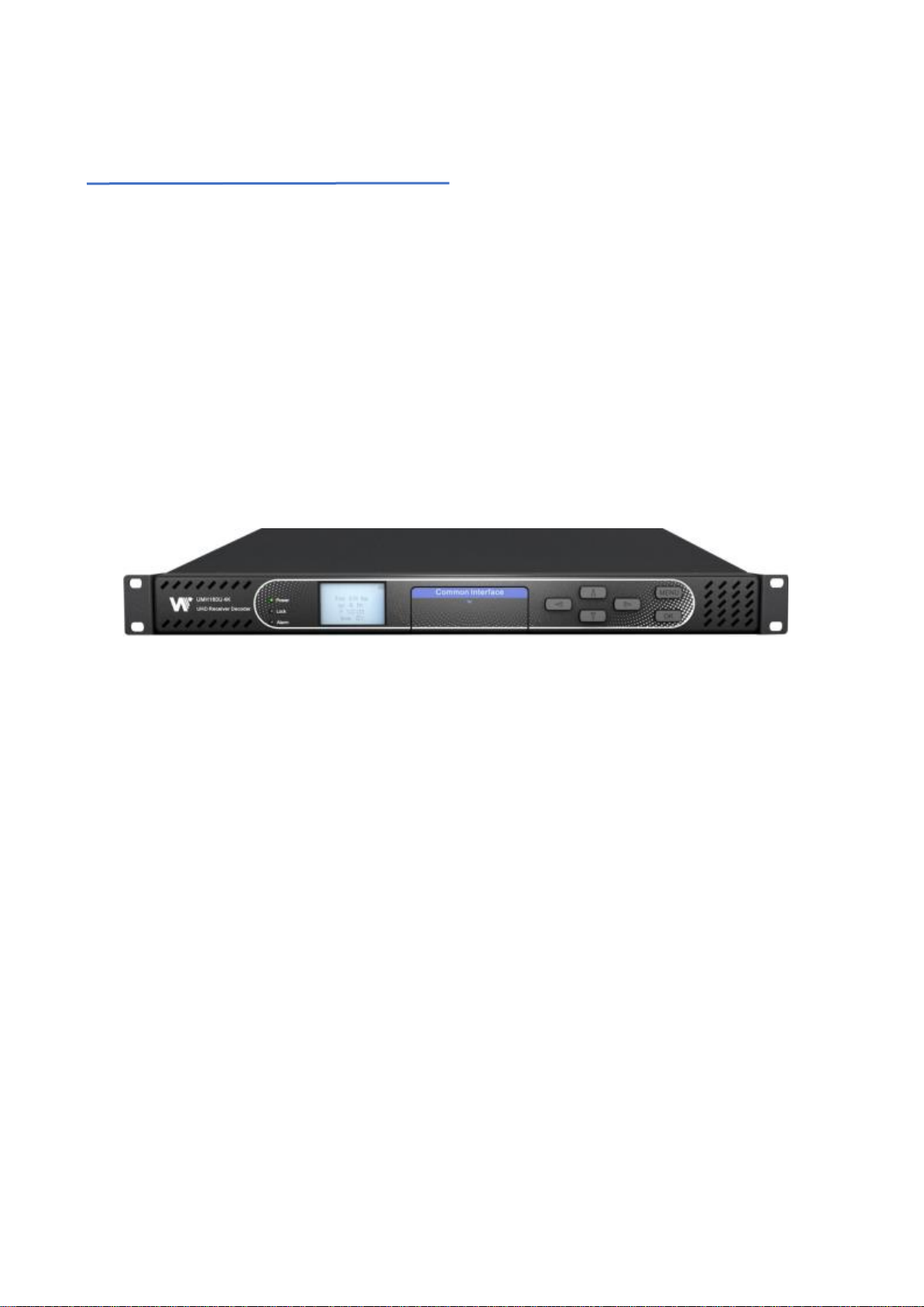
1.1.Product Introduction ..............................................................................................................2
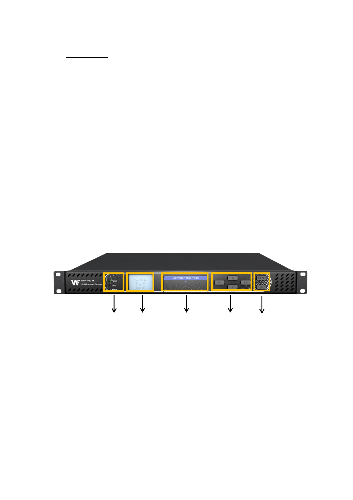
1.2.Front Panel Overview............................................................................................................2
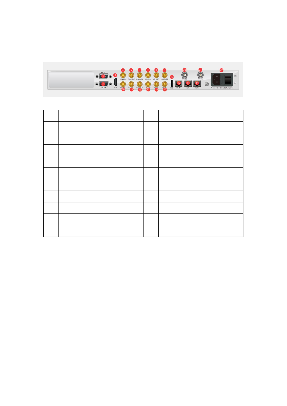
1.3.Rear Panel Overview ............................................................................................................3
1.4.Cooling..................................................................................................................................3
1.5.Rack Information ...................................................................................................................3
2.Installation ....................................................................................................................................4
2.1.Installation Procedure............................................................................................................4
2.2.Preparation before Installation ..............................................................................................4
2.3.AC Power Connection...........................................................................................................5
2.4.DC Power Connection...........................................................................................................5
2.5.Checking Package and Accessories.....................................................................................5
2.6.Maintenance..........................................................................................................................5
3.Operating the front panel..............................................................................................................6
3.1.UMH160UIG Front Panel Overview.................................................................................6
3.2.UMH160UIG Network Setup via Front Panel........................................................................6
3.3.UMH160UIG Management IP address via Front Panel ........................................................7
4.Operating the Web Interface ......................................................................................................10
4.1.UMH160UIG Web Interface Overview ................................................................................10
4.1.1. Logging into the UMH160UIG Web Interface...............................................................10
4.1.2. Hiding Unused Inputs...................................................................................................10
4.1.3. Buttons and Status Indicators ......................................................................................10
4.2.Main panel...........................................................................................................................11
4.2.1. Configuring Active Inputs .............................................................................................12
4.2.2. Configuring ASI Input...................................................................................................14
4.2.3. Configuring TS/IP Input................................................................................................15
4.2.4. Configuring DVB-S/S2/S2X Input.................................................................................16
4.2.5. Configuring DVB-C Input..............................................................................................18
4.2.6. Configuring Network Protocol Input..............................................................................19
4.2.7. Configuring DVB-CI Descrambling...............................................................................22
4.2.8. Configuring Cardless CAS Descrambling ....................................................................23
4.2.9. Configuring T2MI Decapsulation..................................................................................25
4.2.10. Configuring Service Selection....................................................................................26
4.2.11. Configuring Video Services........................................................................................29

4.2.12. Configuring Audio.......................................................................................................30
4.2.13. Configuring Program Multiplex...................................................................................31
4.2.14. Configuring ASI Output ..............................................................................................33
4.2.15. Configuring TS/IP Output...........................................................................................34
4.3.System Panel ......................................................................................................................38
4.3.1. Changing Unit Password..............................................................................................39
4.3.2. Profiles .........................................................................................................................39
4.3.3. Diagnostics...................................................................................................................40
4.3.4. System Information ......................................................................................................41
4.3.5. General Settings...........................................................................................................41
4.3.6. DVB-S2X Preset...........................................................................................................41
4.3.7. Unit Network Configuration ..........................................................................................46
4.3.8. License Information......................................................................................................49
4.3.9. Data/Time.....................................................................................................................50
4.3.10. Syslog.........................................................................................................................51
4.3.11. Updating the UMH160UIG .........................................................................................52
4.3.12. Reboot Unit ................................................................................................................54
4.3.13. Reset Defaults............................................................................................................54
4.4.Log Panel............................................................................................................................55
4.4.1. Active Alarms ...............................................................................................................55
4.4.2. Event Logs ...................................................................................................................56
4.4.3. Configuring the Logs....................................................................................................57
5.Appendices................................................................................................................................60
5.1.Acronyms and Glossary ......................................................................................................60
5.2.Specifications ......................................................................................................................64

Preface
About This Manual
This manual provides introduction to users about how to operate the device correctly. The
content includes introduction to product installation, product characteristics and product
settings, etc. It is highly suggested that users should read this document before actually
operating the device.
Intended Readers
This manual is suggested to be studied by the following readers:
⚫
Technical Service Engineer
⚫
Maintenance Engineer
⚫
Test Engineer
⚫
Sales Engineer
Symbols Definition
For the symbols that might appear in this document, the meanings they represent are as the
following:
Symbol
Meaning
There is highly potential danger. If it cannot be avoided, it will lead to the deaths or
serious injury.
There is medium or low potential danger. If it cannot be avoided, it will lead to medium
or slight injury.
There are potential risks. If ignore these texts, it may cause damage to the device,
data loss, equipment performance reduce or unpredictable results.
Tips that help you to solve problems or save your time.
Remarks. Additional information to the text, in order to emphasize something.

1. Overview
1.1.Product Introduction
UMH160UIG is a powerful and cost-effective 4K receiver/decoder that supports MPEG-
2/H.264/H.265/AVS+/AVS2 UHD/HD/SD video decoding and major audio decoding. With
ample tuner input options and multiple input/output interfaces, it can achieve the RF
signal reception, program descrambling, multiplexing, downscaling and decoding output.
With IP-based stream processing and management interfaces, it is ideal to support
advanced content distribution, 4K decoding, content remultiplexing, digital signal
turnaround and transmission via an all-lP-headend system.
1.2.Front Panel Overview
1. Power status indicator: This LED light is turned on when the IRD is power on.
2. Lock status indicator: This LED light is turned on when a channel is locked.
3. Alarm status indicator: This LED flickers when there is something abnormal.
4. LCD screen: This LCD screen can show the program and configuration information.
5. CI slots: There are two CI slots for various CAS CAM (PCMCIA) modules.
6. Up/Down/Left/Right buttons: To change channels, to adjust volumes and configure the
IRD.
7. Menu button: To enter the menu and the quit function of the sub menus.
1,2,3 4 5 6 7,8

8. OK button: To confirm the operation in the setup.
1.3.Rear Panel Overview
1
RELAY
2
AUDIO OUT
3
HDMI
4
AES/EBU
5
CVBS OUT
6
R-AUDIO1
7
R-AUDIO2
8
ASI OUT1
9
ASI OUT2
10
SDI OUT1
11
SDI OUT2
12
L-AUDIO1
13
L-AUDIO2
14
ASI IN1
15
ASI IN2
16
USB
17
MGMT
18
TS/IP 1
19
TS/IP 2
20
RF IN2
21
RF IN1
22
POWER SUPPLY
1.4.Cooling
The UMH160UIG is cooled via forced induction through the front of the unit and
exhausted through the vents in the rear of the chassis. The UMH160UIG is equipped
with a temperature controlled status indicator. If the temperature inside the unit
exceeds 60°C the red “Error” text will illuminate on the front panel and a description of
the error will appear in the “Error List.
1.5.Rack Information
The UMH160UIG is intended to be mounted in a standard 19”rack. It occupies 1RU
of rack space and the connections are all on the rear of the unit.

2. Installation
2.1.Installation Procedure
The UMH160UIG is designed to be mounted in a standard 19” rack. It takes 1RU of rack
space. To install it into a rack, please use the following steps:
1. Determine the desired position in the rack for the UMH160UIG. Make sure
that the air intake on the top of the unit and the exhausts on the back of
the unit will not be blocked.
2. Install the brackets at desired position if there’s no supporting plate in the
rack.
3. Insert the rack mount clips into place over the mounting holes in the rack.
4. Slide the UMH160UIG into the position in the rack.
5. Secure the chassis to the rack by installing the four supplied screws
through the front mounting holes and tightening.
2.2.Preparation before Installation
Before installation, the installation personnel should read through and confirm the
followings:
⚫Go through this user manual.

⚫Has the knowledge of digital television system.
⚫Has defined the sources, racks allocation, and set-up plan system wiring.
⚫Knows how to operate this unit and parameters configuration.
⚫Go through related engineering design documents about the system.
2.3.AC Power Connection
Please only use the supplied 3-prong power connector or one with equal specifications.
NEVER tamper with or remove the grounding pin. This could cause damage to
UMH160UIG, personnel, or property. Make sure the power outlet is switched off before
plug or unplug the power cable from the panel of UMH160UIG.
2.4.DC Power Connection
The UMH160UIG with the DC chassis option is intended for use on 48V DC systems. A
power cable is not included for this option. In order to apply power to the unit in this
configuration, simply connect the screw terminals on rear of the unit to the rack’s DC
power rails.
Be sure that the power source and cable is used in conjunction with an over-current
protective device rated at 50V, 5A, type: Slow-blo fuse as part of battery-supply circuit.
Also, to reduce the risk of shock and damage to equipment, it is recommended that the
chassis grounding screw (1.3) located on the rear of the UMH160UIG –be connected to
the installation’s rack, battery negative terminal, and/or earth ground.
2.5.Checking Package and Accessories
⚫Base Unit x1
⚫Power cord x1
⚫Earth cord x1
⚫BNC cord x1
⚫BNC-RCA cord x2
2.6.Maintenance
The UMH160UIG is virtually a maintenance-free piece of equipment. There are no user
serviceable parts on the inside of the unit.

3. Operating the front panel
3.1.UMH160UIG Front Panel Overview
The UMH160UIG front panel allows the user to configure all settings that are present in
the web interface using the buttons located on the front of the unit. The screen below is
the idle screen of the UMH160UIG. This idle screen allows the user to view the incoming
bitrate of the active input, which input is set to active, the management IP address of the
unit and the service currently set to decode.
3.2.UMH160UIG Network Setup via Front Panel
1. Bitrate of incoming stream displayed in Mbps.
2. Current active input.
3. IP address of management port.
4. Current decoded service.
The following figure shows a typical screen on the front panel. Several important features
have been circled and noted below. These features are common to all screens and assist

when navigating, viewing and editing unit information. The button allows the user
to return to the home screen, cancel settings and go back a menu. In order to edit a
selected parameter the button must be pressed. Once a parameter has been
changed the button must be pressed again before the change takes effect on the
unit.
3.3.UMH160UIG Management IP address via Front Panel
To setup the UMH160UIG with a Static IP address, use the following steps:
1. Press the button to “Main Manu”.
2. Use the and buttons to move the
cursor to “System”
3. Use the and buttons to move the
cursor to “Unit Networking”.

4. Use the and buttons to move the
cursor to “MGMT configuration”
5. Press button to start the change mode.
6. Use the and buttons to move the
cursor to “IP Mode”, press the button.
7. Press button to start the change mode
8. Use the or buttons to select “Static”
and press button.
9. Use the buttons to move the cursor to “IP”,
press button.
10. Use the and buttons to select the
column to edit and use the and buttons to
change the IP, then press the button.

11. The cursor will now be on “Mask”.
12. Use the and buttons to select the
column to edit and use the and buttons to
change the Subnet Mask, then press the
button.
13. The cursor will now be on “GW” which is gateway.
14. Use the and buttons to select the
column to edit and use the and buttons to
change the Gateway, then press the button.
DHCP
The UMH160UIG can be configured to use DHCP to obtain an IP address/Subnet
Mask/Gateway.
1. Use the and buttons to move the cursor
to “IP Mode”, press the button.
2. Use the or buttons to select “DHCP”
and press button to save the selection.

4. Operating the Web Interface
4.1.UMH160UIG Web Interface Overview
4.1.1. Logging into the UMH160UIG Web Interface
The user will need to login to the web interface. Press the login button in order to login to
the web interface.
Default Credentials
IP address:10.0.0.74
Username: admin
Password: mpeg101
4.1.2. Hiding Unused Inputs
The UMH160UIG web interface allows the user to hide inactive inputs using the
button or show all available inputs by click the
button. Only the inputs configured as the Primary Input and
Backup Input will be displayed when unused inputs are hidden.
4.1.3. Buttons and Status Indicators
When the button is shown user configuration is available. Clicking this button will open

menus where settings can be changed by the user.
When the icon is shown additional status information can be viewed. Click this button
will expand the menu to display the additional status information.
Status in the UMH160UIG web interface is shown with LED status indicators:
Green LED
Status is good. No errors are present and function is
operating normally.
Red LED
Status indicates function is affected by active error. To view
the errors navigate to Alarms panel to view Active Errors
Gray LED
Status is inactive. Function is currently disabled or
unavailable
4.2.Main panel
The Main panel of the UMH160UIG web interface is used to configure the unit to decode,
de-encapsulate and demodulate. When configuring the UMH160UIG the user begins at
the top of the menu and works down. The inputs are configured, then descrambling (if
present), then service or PIDs are selected for decode, then outputs are configured.
Pictured below is a fully populated unit with all options licensed.

4.2.1. Configuring Active Inputs
This menu allows the user to configure a primary and backup input. In case there is an
input failover the UMH160UIG is capable of detecting the failed state and switching to a
secondary backup input in order to provide a continuous output. Which input is primary
and backup, how the inputs switchover and restore and switchover timing is all user
configurable. The user can force the UMH160UIG to switch between the Primary and
Backup Inputs by clicking the button. To change the active input and
failover settings click the button next to Input Selection:
Active Input Indicator

General options for Input 1 configuration
Setting
Range
Description
Primary Input
DVB-S2X Port1
DVB-S2X Port2
ASI Port1
ASI Port2
TS/IP Stream 1
TS/IP Stream 2
TS/IP Stream 3
TS/IP Stream 4
Network protocol
Used for both normal operation and
input failover settings. During normal
operation this input will be the active
input.
Note: Depending on the tuner module
that is installed, the menu will change
to reflect the applicable input type.
Backup Input
DVB-S2X Port1
DVB-S2X Port2
ASI Port1
ASI Port2
TS/IP Stream 1
TS/IP Stream 2
TS/IP Stream 3
TS/IP Stream 4
Network protocol
During failover operation this input will
become the active input. The catalyst
for what causes the unit to switch to
this input is configured in the following
setting.
Note: Depending on the tuner module
that is installed, the menu will change
to reflect the applicable input type.
Other manuals for UMH160UIG
1
Table of contents
Other Wellav Media Converter manuals

Wellav
Wellav NB100 User manual

Wellav
Wellav CMP201 User manual

Wellav
Wellav UMH252 User manual

Wellav
Wellav CMP100 User manual

Wellav
Wellav DMP900 User manual

Wellav
Wellav UMH160UIG User manual

Wellav
Wellav NB100U User manual

Wellav
Wellav UMH160R User manual

Wellav
Wellav SMP181-HLS User manual

Wellav
Wellav NB100U User manual