Wellav SMP181-HLS User manual

SMP181-HLS
User Guide
V1.1-N
DVBCommunity - cообщество профессионалов ЦТВ
https://dvbcommunity.ru/

SMP181-HLS User Guide
i
Revision History
Date
Version
Description
Author
12/8/2016
1.0
First Draft
MS
3/5/2017
1.1-N
UI Update
HL
This guide contains some symbols to call your attention.
DANGER
The DANGER symbol calls your attention to a situation that, if ignored, may cause
physical harm to the user.
CAUTION
The CAUTION symbol calls your attention to a situation that, if ignored, may cause
damage to Our product.
NOTE
The NOTE symbol calls your attention to important information.
TIP
The TIP symbol calls your attention to additional information that, if followed, can
make procedures more efficient.
This guide also contains the following text conventions.
Black Bold
Indicates a button to click, or a menu item to select.
DVBCommunity - cообщество профессионалов ЦТВ
https://dvbcommunity.ru/

SMP181-HLS User Guide
ii
Contents
PART 1 SMP181 CHASSIS OVERVIEW ···························································································································· 1
1.1 FRONT PANEL OVERVIEW·················································································································································· 1
1.2 REAR PANEL OVERVIEW···················································································································································· 1
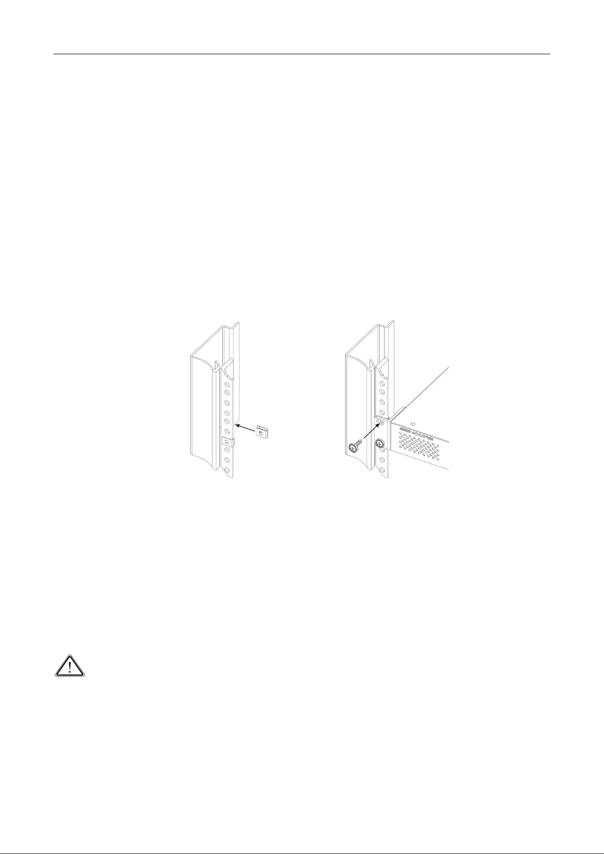
PART 2 RACK INSTALLATION········································································································································· 2
PART 3 WEB UI OVERVIEW ··········································································································································· 3
3.1 WEB UI INTRODUCTION···················································································································································· 3
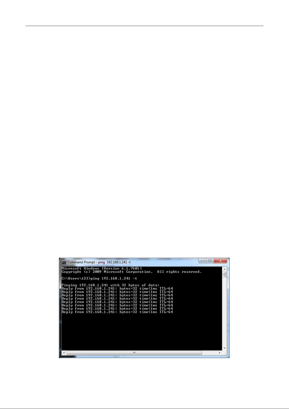
3.1.1 Connecting to the Management Port·················································································································· 3
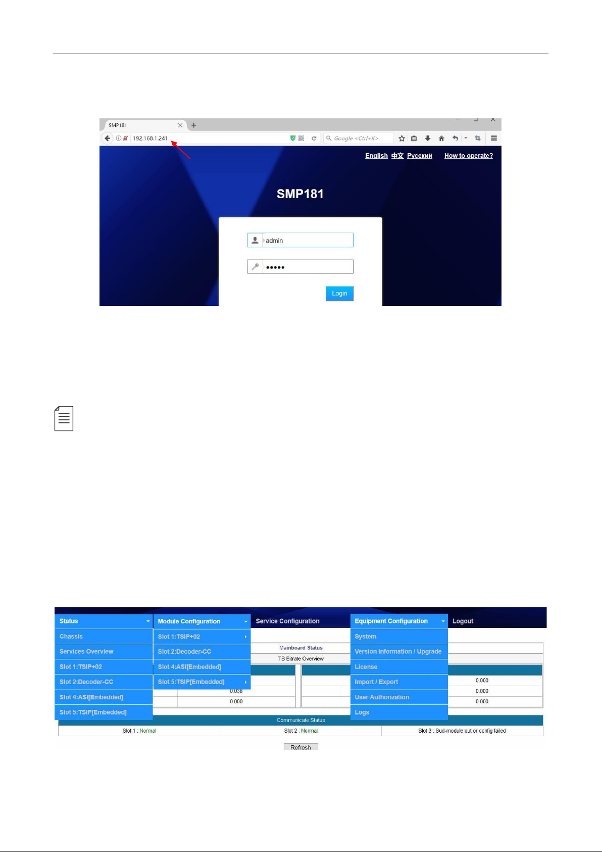
3.1.2 Logging into the Web User Interface ·················································································································· 4
3.1.3 Dropdown Menu ················································································································································· 4
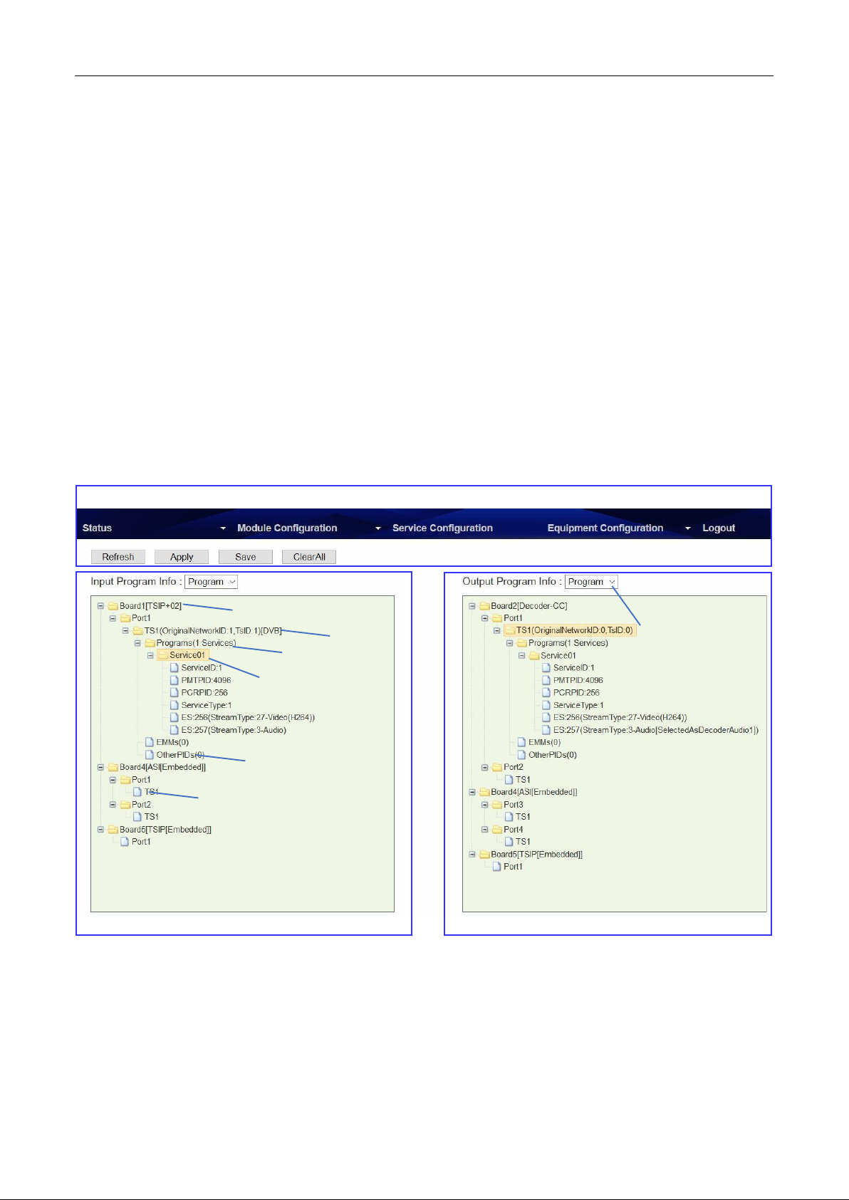
3.1.4 Service Configuration Introduction······················································································································ 5
PART 4 INPUT AND OUTPUT ········································································································································· 6
4.1 CONFIGURING INPUT························································································································································ 6
4.1.1 HLS Input ····························································································································································· 6
4.1.2 Built-in ASI Input·················································································································································· 7
4.1.3 Built-in IP Input···················································································································································· 8
4.2 CONFIGURING OUTPUT··················································································································································· 10
4.2.1 Decoder ····························································································································································· 10
4.2.2 Built-in ASI Output············································································································································· 11
4.2.3 Built-in IP Output··············································································································································· 11
4.2.4 Configuring Output in Service Configuration ···································································································· 12
4.3 OTHER CONFIGURATIONS················································································································································ 14
4.3.1 Delete Input TS ·················································································································································· 14
4.3.2 Bypass Input TS ················································································································································· 14
4.3.3 Delete a Output TS/Program/PID······················································································································ 14
4.3.4 Edit TS Info ························································································································································ 15
4.3.5 PSI/SI ·································································································································································15
PART 5 EQUIPMENT CONFIGURATION·························································································································16
5.1 SYSTEM ······································································································································································· 16
5.2 VERSION INFORMATION/UPGRADE ··································································································································· 16
5.3 LICENSE ······································································································································································· 17
5.4 IMPORT/EXPORT CONFIGURATION···································································································································· 17
5.5 LOGIN USER MANAGEMENT ············································································································································ 18
5.6 LOG ············································································································································································ 18
PART 6 APPENDICES ····················································································································································19
APPENDIX A-WARRANTY····················································································································································· 19
APPENDIX B-AFTER-SALES SUPPORT······································································································································ 19
DVBCommunity - cообщество профессионалов ЦТВ
https://dvbcommunity.ru/

SMP181-HLS User Guide
iii
SAFETY INSTRUCTIONS
Read these instructions
Keep these instructions
Follow all instructions
Heed all warnings
Do not use this unit near water.
Only use a damp cloth to clean chassis
Do not install near any heat sources such as radiators, heat registers, stoves, or other
apparatus (including amplifiers) that produce heat
Do not block any ventilation openings. Install in accordance with the manufacturer’s
instructions
This unit is grounded through the power cord grounding conductor. To avoid electrocution,
do not remove the power cord before the outlet is switched off or unplugged. If the plug does
not fit into your outlet, consult an electrician for replacement of the outlet.
Route power cords and other cables so that they are not likely to be damaged.
Only use attachments/accessories specified by the manufacturer.
Do not wear hand jewelry or watch when troubleshooting high current circuits.
Do not work on the system during periods of lightning.
Refer all servicing to qualified service personnel. Servicing is required when this unit has
been damaged in any way.
Damage Requiring Service: Unplug this product from the wall outlet and refer servicing to
qualified service personnel under the following conditions:
When the power-supply cord or plug is damaged.
If liquid has been spilled, or objects have fallen into the product.
If the product has been exposed to rain or water.
If the product does not operate normally by following the operating
instructions. Adjust only those controls that are covered by the operating
instructions as an improper adjustment of the controls may result in
damage and will often require extensive work by a qualified technician to
restore the product to its normal operation.
If the product has been damaged in any way.
Replacement Parts: When replacement parts are required, be sure the service technician
uses replacement parts specified by the manufacturer. Unauthorized part substitutions made
may result in fire, electric shock or other hazards.
DVBCommunity - cообщество профессионалов ЦТВ
https://dvbcommunity.ru/

SMP181-HLS User Guide
iv
Safety Precautions
There is always a danger present when using electronic equipment.
Unexpected high voltages can be present at unusual locations in defective equipment and
signal distribution systems. Become familiar with the equipment that you are working with
and observe the following safety precautions.
Every precaution has been taken in the design of the products to ensure that it is as safe as
possible. However, safe operation depends on you the operator.
Always be sure your equipment is in good working order. Ensure that all points of connection
are secure to the chassis and that protective covers are in place and secured.
Never work alone when working in hazardous conditions. Always have another person close
by in case of an accident.
Always refer to the manual for safe operation. If you have a question about the application or
operation contact your provider for assistance.
Electrostatic Discharge (ESD) Caution:
Always wear an ESD-preventive wrist or ankle strap when handling electronic components.
Handle cards by the faceplates and edges only. Avoid touching the printed circuit board and
connector pins.
Avoid touching any electronic components while holding any module in hands.
Danger of explosion if battery is incorrectly replaced.
DVBCommunity - cообщество профессионалов ЦТВ
https://dvbcommunity.ru/

SMP181-HLS User Guide
1
Part 1 SMP181 Chassis Overview
1.1 Front Panel Overview
SMP181-HLS is a 2-channel decoder with HLS stream receiving interfaces. On the back of its
chassis, there also built-in ASI and IP I/O interfaces.
1. Indicators ( For Power, ASI, TS/IP and decoder status)
Red or Flashing Red : Error
Green: Normal
Flashing Green: Initialing or loading a board
2. LCD Screen
3. Up, Down, Left, and Right buttons
4. Menu, OK, and Esc buttons
1.2 Rear Panel Overview
On the back panel of the chassis, there three slots available for different boards. In SMP181, the
HLS TSIP board is in slot1, and the Decoder board is in slot2. Slot 3 is empty.
4
1
2
3
DVBCommunity - cообщество профессионалов ЦТВ
https://dvbcommunity.ru/

SMP181-HLS User Guide
2
Part 2 Rack Installation
Rack Installation
The SMP181 is designed to be mounted in a standard 19” rack. It takes 1RU of rack space. To install
it into a rack, please use the following steps:
1. Determine the desired position in the rack for the SMP181. Make sure that the air intake
on the top of the unit and the exhausts on the back of the unit will not be blocked.
2. Install the brackets at desired position if there’s no supporting plate in the rack.
3. Insert the rack mount clips into place over the mounting holes in the rack.
4. Slide the SMP181 into the position in the rack.
5. Secure the chassis to the rack by installing the four supplied screws through the front
mounting holes and tightening.
Note the SMP181 chassis is cooled via inbuilt fans. Operating temperature is within 0~50°C.
AC Power Connection
Only use the supplied 3-prong power connector or one with equal specifications. NEVER tamper
with or remove the grounding pin. This could cause damage to the equipment, personnel, or
property. Make sure the power outlet is switched off before plug or unplug the power cable from the
back panel. Power unit is designed to work under condition of AC100~240V, 50/60Hz. Max
consumption is 50W.
When you move this device from a cold condition into a warmer condition, it should be
acclimated to the warm and humidity condition for at least 30 minutes. Powering up a non-
acclimated unit may lead to shortcut or other damage to electronic components.
DVBCommunity - cообщество профессионалов ЦТВ
https://dvbcommunity.ru/

SMP181-HLS User Guide
3
Part 3 Web UI Overview
3.1 Web UI Introduction
3.1.1 Connecting to the Management Port
Factory network settings of the Management Port:
IP address 192.168.1.241
Subnet Mask 255.255.255.0
Gateway 192.168.1.1
Use the following step to access the Web UI in a browser.
Connect both SMP181’s management port and the computer’s Ethernet port to a switch by
CAT5 straight-through cables. If you do not have a switch, you can connect the computer
directly to SMP181’s management port.
Set the IP address of the laptop/computer in the same network with the SMP181 management
IP address. For example, you can set the computer’s IP address to 192.168.1.242.
Check the physical connection via Command Prompt (Try to click the Windows Menu Icon in
the corner of the desktop, and hit “CMD “, then press “Enter”, you will open the Command
Prompt). Type “ping 192.168.1.241” or “ping 192.168.1.241 –t” and press “Enter” to check reply
status. Stable and constant replies from 192.168.1.242 (management computer’s IP address)
indicate a reliable physical connection. See the following image.
DVBCommunity - cообщество профессионалов ЦТВ
https://dvbcommunity.ru/

SMP181-HLS User Guide
4
3.1.2 Logging into the Web User Interface
Type the management IP address into the URL field of any recommended browser (IE8 or above,
Firefox, and Google Chrome) to access the logon page. By default, the admin user account is
admin with password admin. Click Login or press Enter on the keyboard to login to the web
interface.
We use only IE, Firefox and Chrome for testing procedures. If you use other browsers, like
Microsoft Edge, you may encounter incomplete UI layouts, and configure setting in these browsers
may lead to errors.
3.1.3 Dropdown Menu
On the top of the Web UI, you will find a couple of menu items. Move the cursor to each item to
navigate through the dropdown menus. Menu item with a small white arrow on the right contains
submenu items. See the menu structure in the following image.
DVBCommunity - cообщество профессионалов ЦТВ
https://dvbcommunity.ru/

SMP181-HLS User Guide
5
Status pages summarize the input and output bitrate in each board.
Module Configuration is where you set input and output parameters for each board.
Service Configuration is where to distribute services. See 3.1.4
Equipment Configuration includes the basic settings for a SMP181 unit.
3.1.4 Service Configuration Introduction
Service Configuration page, see the following image, is the main page to distribute input and output
services. In the input and output configuration areas, only the slots with modules successfully
loaded are visible, except the scrambler which is hidden in Output Configuration Area and it is
configurable by right-clicking the programs in output ports. Board 1 in this page refers to the module
in slot 1. Board 2 refers to the module in slot 2, and so on.
Function of the Main Buttons in Service Configuration:
Refresh Click to refresh input and output configuration or parameters. There are also Refresh buttons of
the same function in other pages.
Menu and Main Buttons
Slot and Module Name
Output Configuration Area
Quick Sort
Port and Port Number
Other PID Group
Input Configuration Area
TS
Service Group
Program Name
DVBCommunity - cообщество профессионалов ЦТВ
https://dvbcommunity.ru/

SMP181-HLS User Guide
6
Apply Click to apply the configuration you have just done. There are also Apply buttons in other
pages. Click Apply buttons every time you complete the settings in these pages.
Save Click to save all the configurations into the flash memory. Only in this way will the SMP181 be
able to restore all the configurations after power recycling.
Clear All Click to erase the configurations in Service Configuration. This operation does not remove the
configurations saved in flash memory unless you click Save after Clear All is done.
The login session will expire in 5 minutes without any active operation. Please click Apply at least once
every 5 minutes; otherwise, your work in the last few minutes might be futile because the login session has
stopped without notice.
Part 4 Input and Output
4.1 Configuring Input
4.1.1 HLS Input
Verify the IP input cable is connected to the RJ451 port on the TSIP+02 board. Go to Module
Configuration > TSIP+02 > Setup. Configure the network settings for TSIP+02 board. Click Apply
before you go to the next step.
Go to Module Configuration > TSIP+02 > Input. Enable an Input channel, for instance, here we
enable channel 1. Enter the URL address. Click Apply before you go to the next step.
DVBCommunity - cообщество профессионалов ЦТВ
https://dvbcommunity.ru/

SMP181-HLS User Guide
7
Go to Status > TSIP+02, verify the input bitrate, resolution and frame rate are correct.
Go to Service Configuration. Right-click on TS1 to Scan TS. After the scan, the service will be
listed under TS1. See the following image, we have Service01 in TS1.
4.1.2 Built-in ASI Input
Verify the ASI input cable is connected to ASI In port. Go to Status > Slot4 ASI [Embedded], verify
the input bitrates are correct. See the following image.
DVBCommunity - cообщество профессионалов ЦТВ
https://dvbcommunity.ru/

SMP181-HLS User Guide
8
Go to Service Configuration, Right click on ASI input TS1 to scan the input stream.
4.1.3 Built-in IP Input
Go to Module Configuration > Slot5 TSIP [Embedded] > Setup. Configure network settings for
the embedded TSIP board. Click Apply before you go to the next step.
Go to Module Configuration > Slot5 TSIP [Embedded] > Input. Check the small boxes to open
the input channels. Choose Protocol, enter address and port. Click Apply before you go to the next
step.
DVBCommunity - cообщество профессионалов ЦТВ
https://dvbcommunity.ru/

SMP181-HLS User Guide
9
Go to Status > Slot5 TSIP [Embedded], verify the input bitrate of each IP input channels.
Go to Service Configuration and Scan TS. Refer to ASI input configuration steps.
DVBCommunity - cообщество профессионалов ЦТВ
https://dvbcommunity.ru/

SMP181-HLS User Guide
10
4.2 Configuring Output
4.2.1 Decoder
Go to Module Configuration > Decoder CC. Two decoding channels are available. See the
following image.
Some of the items have optional settings:
Aspect Ratio Conversion Auto, 4:3 Letter Box, 4:3 Pan and Scan, 16:9 Letter Box, 16:9 Pan and Scan
Output Resolution
Fail Mode Still Image, Black Screen
DVBCommunity - cообщество профессионалов ЦТВ
https://dvbcommunity.ru/

SMP181-HLS User Guide
11
Mixer Stereo, Left, Right, Mono, Dual
Line 4 ~ 9
Audio Group Off, Audio1 PCM, Audio2 PCM
Refer to 4.2.4 about how to distribute a service to the Decoder.
4.2.2 Built-in ASI Output
Go to Module Configuration > Slot4 ASI [Embedded], Enter a Constant Rate for the ASI port.
This Constant Rate shout be at least 2 Mbps higher than the Effective Rate in an ASI Output port.
Click Apply before you go to the next step.
Go to Service Configuration. Distribute an input TS to the ASI output Port. Refer to 4.2.4
.
4.2.3 Built-in IP Output
Go to Module Configuration > Slot5 TSIP [Embedded] > Output.
DVBCommunity - cообщество профессионалов ЦТВ
https://dvbcommunity.ru/

SMP181-HLS User Guide
12
Check the small boxes to open output channels. Choose Protocol. Enter IP address, Dest Port
and Constant Rate. Click Apply before you go to the next step.
Go to Service Configuration. Distribute an input TS to the TSIP output Port. Refer to 4.2.4
4.2.4 Configuring Output in Service Configuration
Drag a service to the Decoder
Go to Service Configuration, right-click on the TS1 under Board2. Click Add TS to generate
an empty TS in Port1. An empty TS contains 0 service.
Long click on a service in the input TS, and drag it to the Program in the Decoder Port1 TS1.
Drop it until a blue arrow appears on the left of the Program. Click Apply.
See the following image. There is an input service (High Definition Jade) in ASI Port1 TS1. After
drag-and-drop operation, you can see it in Decoder Port1 TS1.
DVBCommunity - cообщество профессионалов ЦТВ
https://dvbcommunity.ru/

SMP181-HLS User Guide
13
One Decoder Port decodes only one service. But you can drag more than one service from
input to embedded ASI and TSIP output TS’s, which is called multiplexing.
Drag a TS to an output port
Right-click on an existing input TS, drag and drop it on an empty output TS. See the following
image. Click Apply.
A TS cannot be distributed to a Decoder Port in this way. You should always generate an
empty TS in Decoder in advance.
DVBCommunity - cообщество профессионалов ЦТВ
https://dvbcommunity.ru/

SMP181-HLS User Guide
14
4.3 Other Configurations
4.3.1 Delete Input TS
Right-click on a TS under an input port. Click Clear TS to remove this input TS. Click Apply.
4.3.2 Bypass Input TS
Right-click on a TS under an input port. Click Bypass TS to passthrough this TS. A bypassed TS
and the services in this TS will not be multiplexed. SMP181 will not change anything in a TS if you
bypass it.
4.3.3 Delete a Output TS/Program/PID
Move the cursor to a TS under an output port, a red cross will appear after this TS. Click the red
cross to delete this TS. Click Apply.
DVBCommunity - cообщество профессионалов ЦТВ
https://dvbcommunity.ru/

SMP181-HLS User Guide
15
Move the cursor to any service or PID in this service, you can delete it whenever you can see
the red cross.
4.3.4 Edit TS Info
Right-click a TS under an output port, then click Edit TS Info to change service name, PID’s, TS ID
and Original Network ID.
Be careful when you change any PID value to avoid PID conflict within a TS.
4.3.5 PSI/SI
Right-click a TS under an output port, then click SI Setting to edit NIT, BAT and SDT. This feature
only applies to TS in embedded ASI and TSIP board. It does not apply to the TS in Decoder.
DVBCommunity - cообщество профессионалов ЦТВ
https://dvbcommunity.ru/
Table of contents
Other Wellav Media Converter manuals

Wellav
Wellav UMH252 User manual

Wellav
Wellav UMH160UIG User manual

Wellav
Wellav CMP201 User manual

Wellav
Wellav UMH-150 User manual

Wellav
Wellav NB100U User manual

Wellav
Wellav CMP100 User manual

Wellav
Wellav NB100U User manual

Wellav
Wellav DMP900 User manual

Wellav
Wellav UMH160UIG User manual

Wellav
Wellav UMH160R User manual